Effect of CO Combustion Promoters on Combustion Air Partition in FCC under Nearly Complete Combustion*
2014-07-18 12:09:47WANGRui王銳LUOXionglin羅雄麟andXUFeng許鋒ResearchInstituteofAutomationChinaUniversityofPetroleumBeijing102249China
WANG Rui (王銳), LUO Xionglin (羅雄麟)** and XU Feng (許鋒)Research Institute of Automation, China University of Petroleum, Beijing 102249, China
Effect of CO Combustion Promoters on Combustion Air Partition in FCC under Nearly Complete Combustion*
WANG Rui (王銳), LUO Xionglin (羅雄麟)** and XU Feng (許鋒)
Research Institute of Automation, China University of Petroleum, Beijing 102249, China
With CO combustion promoters, the role of combustion air flow rate for concerns of economics and control is important. The combustion air is conceptually divided to three parts: the air consumed by coke burning, the air consumed by CO combustion and the air unreacted. A mathematical model of a fluid catalytic cracking (FCC) unit, which includes a quantitative correlation of CO heterogeneous combustion and the amount of CO combustion promoters, is introduced to investigate the effects of promoters on the three parts of combustion air. The results show that the air consumed by coke burning is almost linear to combustion air flow rate, while the air consumed by CO combustion promoters tends to saturate as combustion air flow rate increases, indicating that higher air flow rate can only be used as a manipulated variable to control the oxygen content for an economic concern.
fluid catalytic cracking unit, CO combustion promoters, combustion air partition
1 INTRODUCTION
Fluid catalytic cracking (FCC) unit is one of the most important processes in a refinery, so it is essential to be operated near the optimal condition. The performance of the operating condition concerning economics and control should be considered based on an appropriate mathematical model. Despite the efforts for modeling [1-12], control [13-17] and optimization [18-20] of FCC unit during the past decades, the enormous complexity still makes the optimization a challenging problem [21].
The behavior of regenerator dominates the steady state and dynamic behavior of the system, because the heat released by coke burning and CO combustion dominates the conversion in the riser and the residence time of catalyst in the regenerator is much longer than that in the riser. Hence, coke burning and CO combustion in the regenerator are important characteristics for concerns of economics and control.
Several FCC models have considered CO combustion in both homogeneous and heterogeneous phases. In the model proposed by Arbel et al. [3], heterogeneous combustion of CO is related to CO combustion promoters by introducing a factor to represent the relative combustion rate. However, the quantitative correlation between the relative combustion rate and the amount of the added CO combustion promoters was not mentioned. The model proposed by Secchi et al. [8] adopts the same method to simulate the relative heterogeneous combustion rate which did not mention the quantitative correlation, either. The models proposed by Ali et al. [4], Arandes et al. [6], and Han and Chung [7] all adopt the kinetics of CO heterogeneous combustion proposed by Morley and de Lasa [22, 23]. In the work of Fernandes et al. [9, 10], the rate expression for CO heterogeneous combustion is from a technical report by Institut Francais Du Petrole (IFP). In these models, the combustion rate is not quantitatively correlated with the amount of CO combustion promoters added.
On the other hand, for controlling CO combustion in the regenerator, several studies focused on the selection of control structure for FCC unit. Hovd and Skogestad [15] presented a study on the selection of the structure of regulatory control loops in a general FCC unit based on the analysis of linear models derived from the nonlinear model of Lee and Groves [2]. They suggested a 2×2 structure, with catalyst circulation rate controlling riser temperature while combustion air flow rate controlling flue gas oxygen content or regenerator temperature. Based on the dynamic model of an FCC unit with high-efficiency regenerator developed by Fernandes et al. [10], a 4×4 structure was determined for decentralized control [24], with the regenerated catalyst slide valve, spent catalyst slide valve, flue gas slide valve and combustion air flow rate controlling the riser temperature, catalyst inventory in the stripper, regenerator pressure and flue gas oxygen content, respectively. However, the amount of CO combustion promoters is also a measure for controlling the CO combustion together with combustion air flow rate concerning economics of the process. Lacking of a correlation between the amount of CO combustion promoters and CO heterogeneous combustion, these studies have exaggerated the role of air flow rate in the control of CO combustion in the regenerator. Hence, the role of combustion air flow rate for concerns of economics and control should be investigated with the amount of CO combustion promoters added.
In this paper, the combustion air is conceptually divided into three parts: the air consumed by coke burning, the air consumed by CO combustion and theair unreacted. In order to investigate the effect of CO combustion promoters on the combustion air partition, the heterogeneous combustion of CO is quantitatively correlated to the amount of CO combustion promoters added in an FCC unit with high-efficiency regenerator. The effect is discussed based on the sensitivity analysis of CO combustion with respect to the air flow rate and the amount of CO combustion promoters added.
2 MODELING OF FCC UNIT WITH CO COMBUSTION PROMOTERS
The model in this work is based on the dynamic model of an FCC unit with high-efficiency regenerator under complete combustion proposed by Luo [25]. Since the high-efficiency regenerator is generally designed with excess combustion air to guarantee the fast fluidization in the combustor, it is assumed that no CO exists in the regenerator with plenty of CO combustion promoters added in the base model. In order to investigate the mechanism of CO combustion in the regenerator, a detailed CO combustion model for the regenerator is introduced taking into account CO combustion promoters [26]. The schematic diagram of FCC unit with high-efficiency regenerator is illustrated in Fig. 1.
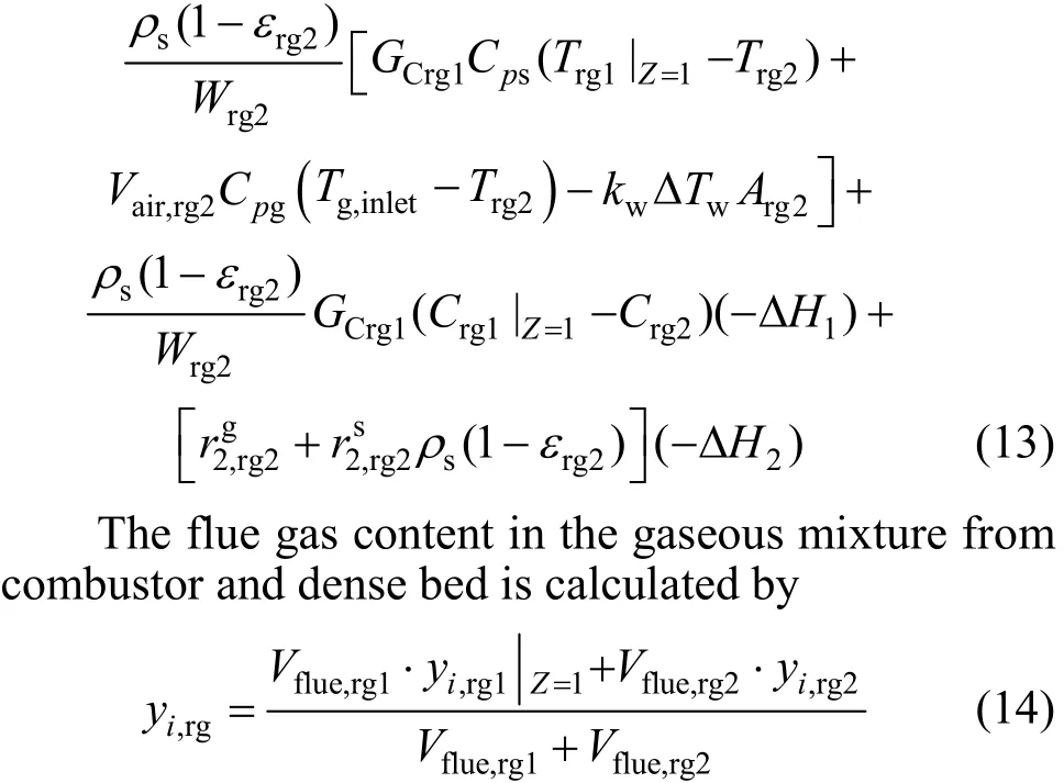
With the assumption that the coke deposited on the spent catalysts is composed of carbon and hydrogen, the reactions in the combustor include
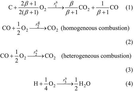
where β is the intrinsic molar ratio CO2/CO, with the correlation proposed by Xu et al. [27]

Consequently, the combustion air is divided into three parts: the air consumed by coke burning Vair,coke, the air consumed by CO combustion Vair,COand the air unreacted in the flue gas Vair,flue, as shown in Fig. 2.
The kinetics for combustion of carbon and hydrogen adopt the model suggested by Lin [28]:
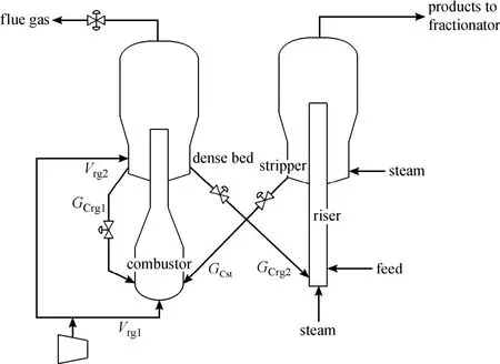
Figure 1 Schematic diagram of FCC unit with high-efficiency regenerator
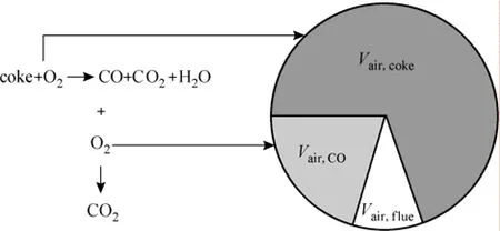
Figure 2 Conceptual partition of combustion air in FCC unit
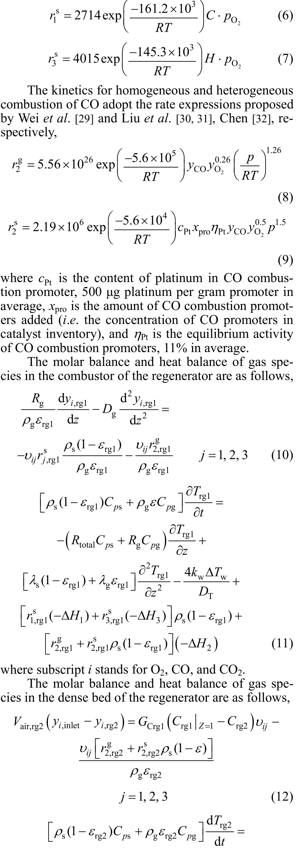
3 EFFECT OF COMBUSTION PROMOTERS ON COMBUSTION AIR PARTITION
In order to investigate the effects of combustion air flow rate and the amount of CO combustion promoters added on CO combustion in the regenerator, sensitivity analysis is performed at different air flow rates and amounts of combustion promoters as illustrated in Fig. 3. The base case operating condition of a 0.7 Mt·a?1FCC unit with high-efficiency regenerator is shown in Table 1.
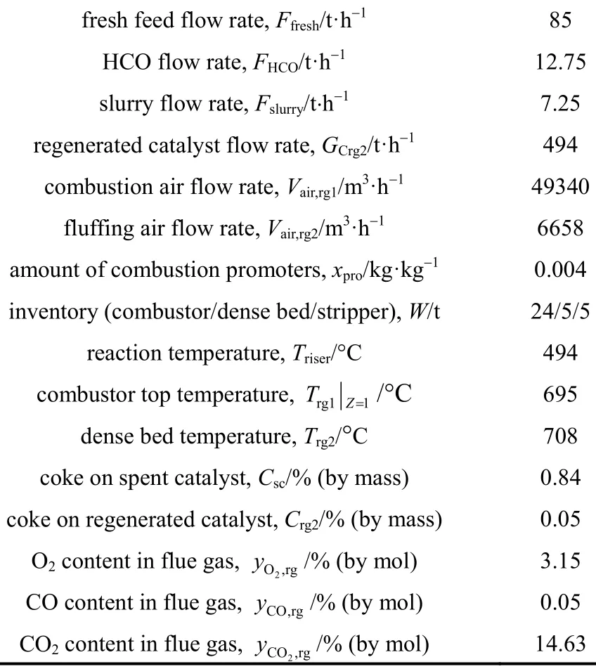
Table 1 Base case operating conditions of FCCU
The effects of combustion air flow rate and the amount of CO combustion promoters on regenerator temperatures in combustor and dense bed are illustrated in Figs. 3 (a) and 3 (b). There exists a maximum temperature in the combustor as the air flow rate increases with the same amount of CO combustionpromoters. This is mainly because when small amount of air is introduced, the partial pressure of oxygen in the combustor is very low, deteriorating the CO combustion and lowering the regenerator temperature, especially with a small amount of promoters. When the air flow rate is too high, the air will function as a coolant to deteriorate coke burning. The regenerator temperature in the dense bed is greatly affected by the condition of the combustor because the air introduced into the dense bed is far less than that into the combustor. Hence, the change of regenerator temperature in the dense bed is similar to that in the combustor. On the other hand, both the temperatures in the combustor and dense bed decrease as the amount of promoters decreases. The effects of the air flow rate and the amount of CO combustion promoters on CO and O2contents in the flue gas and coke content of regenerated catalyst are illustrated in Figs. 3 (c) and 3 (d). The CO content and coke content of regenerated catalyst decrease to certain values as the air flow rate increases while the O2content increases almost linearly to the air flow rate. Fig. 3 illustrates that the air flow rate and the amount of CO combustion promoters both significantly affect the catalyst regeneration. However, CO combustion promoters can only directly promote the CO combustion and do not directly affect coke burning. Therefore, when the cost of CO combustion promoters is concerned, the effect of CO combustion promoters on the air consumed by CO is a key aspect.
For the high-efficiency regenerator, only the air entering the combustor is considered for the partition of combustion air, because the air introduced to the dense bed only assures the incipient fluidization and the coke burned is much less than that in the combustor, which differs greatly from general countercurrent dense bed regenerators. In addition, since the homogeneous combustion rate of CO is much lower than the heterogeneous combustion rate in the presence of CO combustion promoters, the air consumed by CO is mainly by the promotion of CO combustion promoters.
We define the air consumed by coke burning Vair,coke, the air consumed by CO combustion Vair,COand the air unreacted in the flue gas Vair,flueas
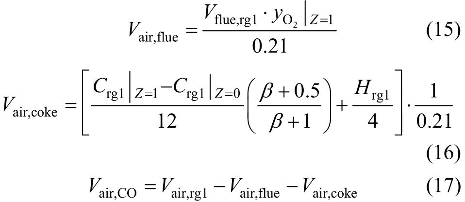
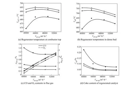
Figure 3 Sensitivity analysis on combustion air flow rate and amount of CO combustion promoters added
Figure 4 (a) shows the partition of combustion air with respect to combustion air flow rate at the amount of CO combustion promoters equal to 0.004, i.e. 2 μgplatinum per gram catalyst. The air unreacted remarkably increases compared to other two parts as the air flow rate increases, indicating that the regeneration is in a quite good condition since the high-efficiency regenerator is commonly operated with excess combustion air and plenty of CO combustion promoters to ensure fast fluidization in the combustor and complete combustion. The effects of promoters on the air consumed by coke burning and CO combustion are illustrated in Figs. 4 (b) and 4 (c). The air consumed by coke burning is almost linear to the air flow rate, while the air consumed by CO combustion promoters tends to saturate as the air flow rate increases, especially when the amount of CO combustion promoters is low. This suggests that there exists an optimal combustion air flow rate with certain amount of CO combustion promoters concerning economics, and beyond this optimal flow rate, increasing combustion air may not significantly increase heterogeneous combustion of CO and the air flow rate can only be used to regulate the oxygen content in the flue gas for an economic concern.
More attention should be paid to the curve with CO combustion promoters of 0.002 in Fig. 4 (c) since the air consumed by CO combustion is far less than those under the other two conditions. In Fig. 3 (c), the CO content in the flue gas with promoters of 0.002 is much higher, indicating the probability of afterburning is higher no matter how much combustion air is injected into the regenerator, namely, combustion air flow rate is no longer an efficient manipulated variable for CO combustion. To prevent afterburning, an increase in the amount of CO combustion promoters is crucial.
Furthermore, from the viewpoint of process design and control, the difference between the amounts of combustion promoters 0.002 and 0.004 and the potential optimal air flow rate at certain amount of promoters provide the potential of reducing the consumption of promoters and operation cost. To obtain an optimized operating condition, the integrated design of process and control based on dynamic simulation is needed in the future.
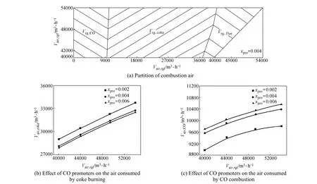
Figure 4 Partition of combustion air and effect of CO promoters on partition
4 CONCLUSIONS
This paper divides combustion air into three parts: the air consumed by coke burning, the air consumed by CO combustion and the air unreacted in the flue gas. To investigate the effects of CO combustion promoters on these parts, a mathematical model of an FCC unit is introduced with a quantitative correlation of CO heterogeneous combustion to the amount of combustion promoters and sensitivity analysis is performed at different combustion air flow rates and amounts of CO combustion promoters. It is indicated that there exists an optimal air flow rate at certain amount of combustion promoters concerning economics and the air flow rate is not an efficient manipulated variable for CO combustion at small amount of combustion promoters.
NOMENCLATURE
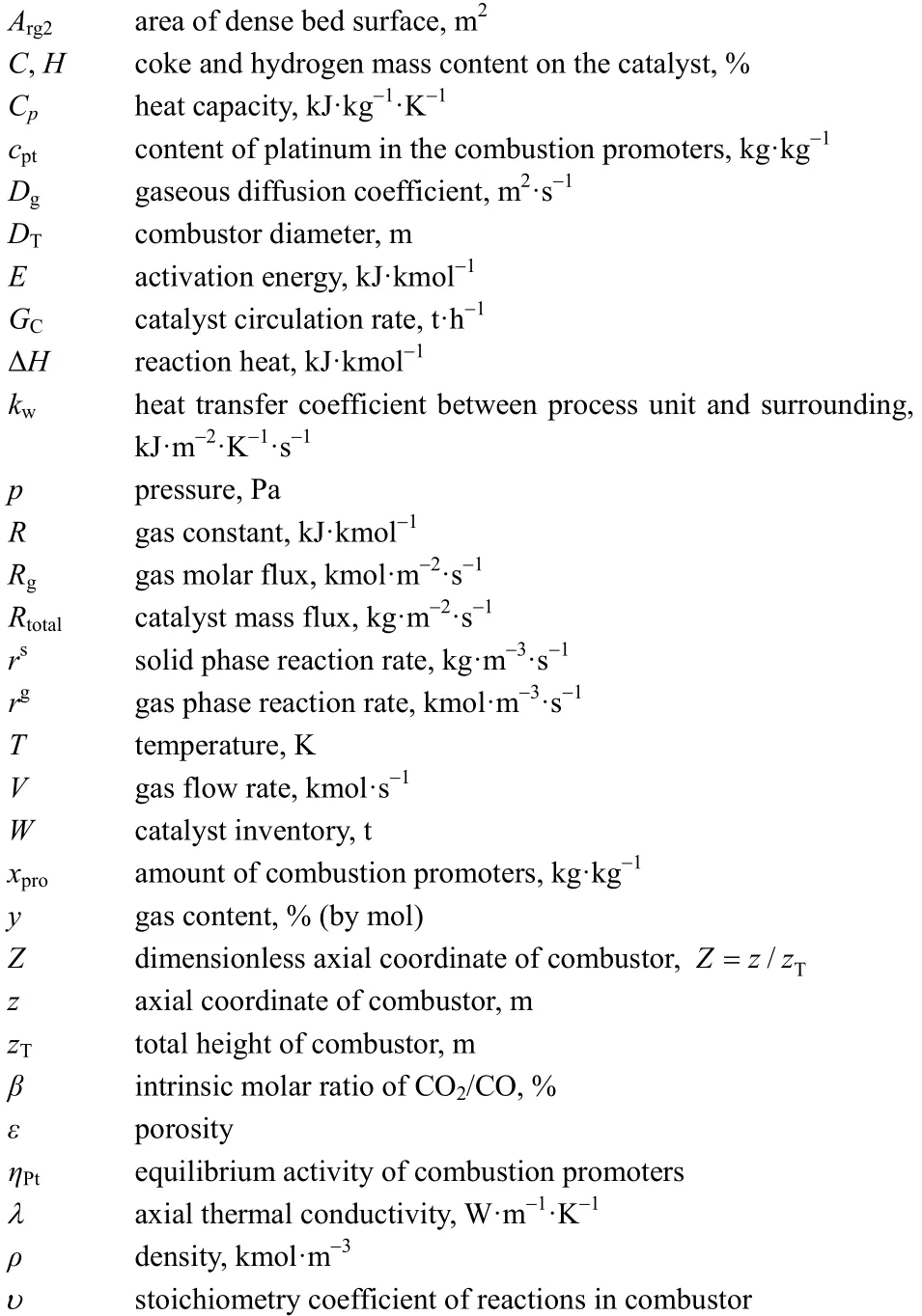
Subscripts
REFERENCES
1 McFarlane, R.C., Reineman, R.C., Bartee, J.F., Georgakis, C., “Dynamic simulator for a model IV fluid catalytic cracking unit”, Computers & Chemical Engineering, 17 (3), 275-300 (1993).
2 Lee, E., Groves, Jr.F.R., “Mathematical model of the fluidized bed catalytic cracking plant”, Transactions, 2 (3), 219-236 (1985).
3 Arbel, A., Huang, Z., Rinard, I.H., Shinnar, R., Sapre, A.V., “Dynamic and control of fluidized catalytic crackers. 1. Modeling of the current generation of FCC’s”, Industrial & Engineering Chemistry Research, 34 (4), 1228-1243 (1995).
4 Ali, H., Rohani, S., Corriou, J.P., “Modelling and control of a riser type fluid catalytic cracking (FCC) unit”, Chem. Eng. Res. Des., 75 (4), 401-412 (1997).
5 Ellis, R.C., Li, X., Riggs, J.B., “Modeling and optimization of a model IV fluidized catalytic cracking unit”, AIChE Journal, 44 (9), 2068-2079 (1998).
6 Arandes, J.M., Azkoiti, M.J., Bilbao, J., de Lasa, H.I., “Modelling FCC units under steady and unsteady state conditions”, The Canadian Journal of Chemical Engineering, 78 (1), 111-123 (2000).
7 Han, I.S., Chung, C.B., “Dynamic modeling and simulation of a fluidized catalytic cracking process. Part i: Process modeling”, Chemical Engineering Science, 56 (5), 1951-1971 (2001).
8 Secchi, A.R., Santos, M.G., Neumann, G.A., Trierweiler, J.O., “A dynamic model for a FCC UOP stacked converter unit”, Computers & Chemical Engineering, 25 (4-6), 851-858 (2001).
9 Fernandes, J.L., Verstraete, J.J., Pinheiro, C.I.C., Oliveira, N.M.C., Ribeiro, F.R., “Dynamic modelling of an industrial R2R FCC unit”, Chemical Engineering Science, 62 (4), 1184-1198 (2007).
10 Fernandes, J.L., Pinheiro, C.I.C., Oliveira, N.M.C., Inverno, J., Ribeiro, F.R., “Model development and validation of an industrial UOP fluid catalytic cracking unit with a high-efficiency regenerator”, Industrial & Engineering Chemistry Research, 47 (3), 850-866 (2008).
11 Gao, J.S., Xu, C.M., Yang, G.H., Guo, Y.C., Lin, W.Y., “Numerical simulation on gas-solid two-phase turbulent flow in FCC riser reactors (I) Tubulent gas-solid flow-reaction model”, Chin. J. Chem. Eng., 6 (1), 12-20 (1998).
12 Gao, J.S., Xu, C.M., Yang, G.H., Guo, Y.C., Wang, X.L., “Numerical simulation on gas-solid two-phase turbulent flow in FCC riser reactors (II) Numerical simulation on the gas-solid two-phase turbulent flow”, Chin. J. Chem. Eng., 6 (1), 21-28 (1998).
13 Cristea, M.V., Agachi, S.P., Marinoiu, V., “Simulation and model predictive control of a UOP fluid catalytic cracking unit”, Chemical Engineering and Processing: Process Intensification, 42 (2), 67-91 (2003).
14 Grosdidier, P., Mason, A., Aitolahti, A., Heinonen, P., Vanham?ki, V.,“FCC unit reactor-regenerator control”, Computers & Chemical Engineering, 17 (2), 165-179 (1993).
15 Hovd, M., Skogestad, S., “Procedure for regulatory control structure selection with application to the FCC process”, AIChE Journal, 39 (12), 1938-1953 (1993).
16 Arbel, A., Rinard, I.H., Shinnar, R., “Dynamics and control of fluidized catalytic crackers. 3. Designing the control system: Choice of manipulated and measured variables for partial control”, Industrial & Engineering Chemistry Research, 35 (7), 2215-2233 (1996).
17 Alvarez-Ramirez, J., Valencia, J., Puebla, H., “Multivariable control configurations for composition regulation in a fluid catalytic cracking unit”, Chemical Engineering Journal, 99 (3), 187-201 (2004).
18 Loeblein, C., Perkins, J., “Structural design for on-line process optimization: II. Application to a simulated FCC”, AIChE Journal, 45 (5), 1030-1040 (1999).
19 Han, I.S., Riggs, J.B., Chung, C.B., “Modeling and optimization of a fluidized catalytic cracking process under full and partial combustion modes”, Chemical Engineering and Processing: Process Intensification, 43 (8), 1063-1084 (2004).
20 Zanin, A.C., de Gouvea, M.T., Odloak, D., “Integrating real-time optimization into the model predictive controller of the FCC system”, Control Engineering Practice, 10 (8), 819-831 (2002).
21 Pinheiro, C.I.C., Fernandes, J.L., Domingues, L., Chambel, A.J.S., Graca, I., Oliveira, N.M.C., Cerqueira, H.S., Ribeiro, F.R., “Fluid catalytic cracking (FCC) process modeling, simulation, and control”, Industrial & Engineering Chemistry Research, 51 (1), 1-29 (2012).
22 Morley, K., de Lasa, H.I., “On the determination of kinetic parameters for the regeneration of cracking catalyst”, The Canadian Journal of Chemical Engineering, 65 (5), 773-777 (1987).
23 Morley, K., de Lasa, H. I., “Regeneration of cracking catalyst influence of the homogeneous CO postcombustion reaction”, The Canadian Journal of Chemical Engineering, 66 (3), 428-432 (1988).
24 Fernandes, J.L., Pinheiro, C.I.C., Oliveira, N.M.C., Inverno, J., Ribeiro, F.R., “Closed-loop dynamic behavior of an industrialhigh-efficiency FCC unit”, In: 16th Mediterranean Conference on Control Automation, Sauter, D., ed., Institute of Electrical and Electronics Engineers, Ajaccio, France, 1829-1834 (2008).
25 Luo, X.L., “Dynamic modeling and operation analysis of FCCU with high efficiency regenerator”, Ph. D. Thesis,China University of Petroleum, Beijing (1997). (in Chinese)
26 Wang, R., Luo, X.L., Xu, F., “Multiple steady states of FCCU with varying CO concentration”, CIESC Journal, 64 (8), 2930-2937 (2013). (in Chinese)
27 Xu, C.M., Lin, S.X., Yang, G.H., “Determination of CO2/CO in dense bed during cracking catalyst regeneration”, Journal of the University of Petroleum, China: Natural Science Edition, 14 (6), 84-93(1990). (in Chinese)
28 Lin, S.X., Petroleum Refining Engineering, 2nd edition, Petroleum Industry Press, Beijing (1988). (in Chinese)
29 Wei, F., Lin, S.X., Yang, G.H., “Kinetic study of gas-phase CO slow oxidation”, Journal of the University of Petroleum, China: Natural Science Edition, 12 (4-5), 110-116(1988). (in Chinese)
30 Liu, D., Sun, P., Liu, X., Wang, J., Ma, F., Zhao, J., “The activity determination of Pt/Al2O3CO-promoted catalyst used in regenerator of catalytic cracking (I) The kinetics of CO oxidation over new Pt/Al2O3promoter”, Chemical Engineering (China), 25 (3), 18-22 (1997). (in Chinese)
31 Liu, D., Liu, X., Wang, J., Sun, P., He, W., Zhao, J., “The activity determination of Pt/Al2O3CO-promoted catalyst used in regenerator of catalytic cracking (II) The determination and simulation of equilibrium activity”, Chemical Engineering (China), 25 (3), 23-26 (1997). (in Chinese)
32 Chen, J.W., Catalytic Cracking Technology and Engineering, 2nd edition, SINOPEC Press, Beijing (2005). (in Chinese)
2013-07-18, accepted 2013-11-08.
* Supported by the National Natural Science Foundation of China (21006127) and the National Basic Research Program of China (2012CB720500).
** To whom correspondence should be addressed. E-mail: luoxl@cup.edu.cn
 Chinese Journal of Chemical Engineering2014年5期
- Chinese Journal of Chemical Engineering的其它文章
- Soft Sensor Model Derived from Wiener Model Structure: Modeling and Identification*
- Kinetics of Forward Extraction of Boric Acid from Salt Lake Brine by 2-Ethyl-1,3-hexanediol in Toluene Using Single Drop Technique*
- Influence of Solvent on Reaction Path to Synthesis of Methyl N-Phenyl Carbamate from Aniline, CO2and Methanol*
- Effect of Adsorbent Diameter on the Performance of Adsorption Refrigeration*
- High-Thermal Conductive Coating Used on Metal Heat Exchanger*
- A Facile Route for Synthesis of LiFePO4/C Cathode Material with Nano-sized Primary Particles*