Use of A Shatter Test Vessel to Assess Propellant Safety
2015-03-08 08:22:12CliveWOODLEYPeterHENNING
火炸藥學報 2015年5期
Clive WOODLEY, Peter HENNING
(QinetiQ, Fort Halstead, Sevenoaks, Kent TN14 7BP, United Kingdom)
?
Use of A Shatter Test Vessel to Assess Propellant Safety
Clive WOODLEY, Peter HENNING
(QinetiQ, Fort Halstead, Sevenoaks, Kent TN14 7BP, United Kingdom)
Abstract:At low temperatures, gun propellant grains may become brittle and this can lead to fracture or shatter of the grains during gun firing. Should this event occur then it will result in an increase in the burning surface of the propellant and will give rise to a change in ballistic performance. Also, if the resultant over pressure is sufficient, a breech failure may result. Understanding the propensity of a grain to fracture or shatter is therefore important in determining its safety in use. This document describes a test that may be used to derive knowledge and to quantify the physical behaviour of a gun propellant grain at the low temperatures at which fracture or shatter is most likely to occur.
Keywords:closed vessel; shatter test; propellant safety
CLC number:TJ55Document Code:AArticle ID:1007-7812(2015)05-0002-10
Received date:2015-08-25;Revised date:2015-09-08
Biography:Clive WOODLEY(1957-), male, research fields: ignition, combustion, gun propulsion
Introduction
Gun propellants are required to be safe to operate over temperatures in the approximate range -40℃ to+70℃. Problems can arise at low temperatures when gun propellant grains can become brittle which may lead to shatter or fracture. Such an event is potentially dangerous during a gun firing because the fracture or shatter leads to a sudden increase in burning surface area which, in turn, often results in pressure waves. These pressure waves may be damaging to the gun, projectile and personnel operating it. Therefore it is important to understand the behaviour of gun propellants at low temperatures under conditions that may be representative of a gun firing.
Quasi-static compression tests are frequently used to give data on the mechanical properties of propellants at different temperatures[1-4]. However, the mechanical response of propellants under dynamic conditions, such as occur in a gun, may be significantly different. The shatter test vessel technique allows an assessment of the propellant mechanical response at all temperatures under dynamic conditions.
The shatter test vessel technique has been reported briefly previously[5]. However, this new paper describes the technique in much greater detail and illustrates the potential response with examples.
1Test Equipment
1.1Test Objectives
The objective of the test is to assess the propensity of propellant grains to fracture and/or shatter at low temperature under the pressure change conditions likely to be experienced during gun firings. It is therefore necessary for the propellant/gun combination to specify the pressure rise rate and temperature for testing. It is also necessary to specify the extent of burning of the propellant test sample required during the test.
1.2Shatter Test Vessel
A schematic drawing of the equipment is shown in Figure 1.
The test uses a 700mL closed vessel containing a modified liner with nominal dimensions 150mm length ×45mm diameter. Propellant grains under test are fitted to a special sample holder plate then cooled to -42℃ before being loaded into the vessel. Prior to loading, the liner is also cooled to -42℃. Under normal firing conditions, such pre-cooling of both samples and liner will ensure that the temperature of the sample at the time of firing, up to 4 minutes after the start of the assembly procedure, is -40℃. It is therefore essential that assembly of the vessel is conducted quickly and that the charge is fired as soon as possible after removal of the sample and liner from the temperature conditioning apparatus at the start of the assembly sequence.
The igniter comprises 1.3g of G12 gunpowder.
Fig.1 700mL Closed vessel modified for shatter test
A fast burning propellant is required to achieve the required pressurization rate. In the UK NC30, usually used as an igniter propellant, was traditionally used but this has been replaced recently by the Vihtavuori propellant N320.
1.3Burst Disc
A breech block, containing a bursting disc assembly (Figure 2), 42g of a secondary propellant charge of NC30 and a gunpowder igniter is then fitted to the vessel and the charge initiated. The rapid burning of the igniter propellant provides the specified pressure rise rate and the rapid build up of pressure caused by the rapid burning of the igniter propellant also causes rupture of the burster disc. This results in rapid adiabatic cooling of the combustion gases and causes any combustion of the grains under test to be halted. Tests grains can then be removed for examination and classification.
Fig.2 Bursting disc assembly
The rate of pressure rise, the maximum pressure in the vessel and the extent of burning of the propellant grains under test is controlled by the bursting pressure, propellant mass and burning characteristics, of the secondary propellant charge. The pressure at which the bursting disc ruptures is controlled by the design and specification of the bursting disc.
The charge of 42g of NC30 propellant in conjunction with a bursting disc assembly comprising two 66×1.6mm mild steel discs has been found to give a maximum vessel pressure of 115MPa and a maximum rate of pressure rise of 220GPa/s (Figure 2). There are two small aligned holes drilled in the discs to allow threading of the ignition wires. These also serve a purpose of relieving the pressure in the vessel in the event of the burst disc not rupturing.
1.4Mounting of the Samples
The test specimen consists of propellant grains mounted on a Tufnol disc, placed in a sample holder and secured within the vessel at the closed end (Figure 3). This arrangement ensures retention of the test specimens within the vessel thus eliminating potential damage caused by secondary impact if the propellant was to be ejected from the vessel.
Fig.3 Mounting of samples
The test specimen comprises seven grains of propellant end-mounted on a Tufnol disc and affixed with a compatible silicone rubber adhesive. Care is taken to avoid significant penetration of the adhesive into any perforations on the end of the propellant grains. This is usually achieved by first sealing the bonding surface with a thin layer of the sealant then, once this sealing coat has cured, application of a second adhesive coat to both propellant grain end and Tufnol disc. Three of these discs comprising 21 separate propellant grains are prepared and fired for each sample under test. If the grain size is such that it does not allow seven grains to fit on the disc, more firings with a smaller number of grains per firing are conducted.
Stick propellant is reduced in size by cutting to 5 cm length prior to fixing to the Tufnol disc. Care is taken during cutting to ensure that cutting does not induce defects in the propellant grain surface.
2Shatter Test Vessel Firing
Testing may be conducted at different conditions (i.e. burst pressure and maximum pressure rise rate). However, it has been found that the conditions of 115MPa and 220GPa/s are sufficiently challenging for propellants used in the UK. Table 1 shows the effect of loading density on maximum pressure rise rate for NC30 propellant and a burst pressure of 115MPa.
Table 1 Effect of loading density on maximum pressure rise rate
Combinations of alternative secondary charge material, loading density and alternative burst pressure can be used to given alternative maximum pressure rise rates and/or alternative level of combustion of the test charge.
Generally a very high burning rate propellant is used as the secondary charge so as to give both the required maximum pressure rise rate and bursting pressure whilst minimising the level of combustion of the test charge. Using alternative secondary charge propellants will change the maximum pressure rise rate and extent of combustion of the test charge. For example, at a fixed loading density, a slower burning secondary charge would be expected to increase the level of combustion of the test charge whilst a faster burning secondary charge would reduce the level of combustion. This would be at the expense of a lower or higher pressure rise rate, respectively. As can be seen for NC30 in Table 1, increasing the loading density for a specific secondary charge and bursting pressure will increase the maximum pressure rise rate. Finally the bursting pressure can be varied in order to derive the required maximum pressure rise rate and degree of combustion of the test charge. This can be achieved by using an alternative bursting disc arrangement consisting of possibly less or more bursting discs or discs with a greater or smaller thickness. Care should, however, be taken to ensure that the bursting pressure remains within the design envelope of the closed vessel used for the testing.
3Shatter Test Vessel Results
After the firing has been conducted, the Tufnol disc is recovered and the samples inspected for damage. The criteria used for judging the tendency of the propellant to shatter are summarized in Table 2. Examples of each category are shown in Figures 4-8.
Table 2 Categorisation of test samples
Fig.4 Examples of Category 5
Fig.5 Examples of Category 4
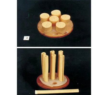
Fig.6 Examples of Category 2

Fig.7 Example of Category 1
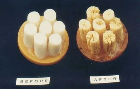
Fig.8 Example of Category 0
4Conclusions
A methodology using a shatter test vessel has been described that helps to assess the tendency of propellant grains to shatter under gun firing conditions.
The method to interpret and categorise the results from the tests has been described with the use of examples.
This technique can be used together with the quasi-static compression technique to improve the safety of gun propellant charges.
References:
[1]Lieb R J, Leadore M G. Mechanical response of gun propellant beds at low strain rates, ARL-TR-78[R]. Washington D C: NASA, 1993.
[2]Lieb R J, Leadore M G. Mechanical response comparison of gun propellants evaluated under equivalent time-temperature conditions, ARL-TR-228[R]. Washington D C: NASA, 1993.
[3]Leadore M G, Lieb R J, High-rate mechanical response and SEM morphology of EX99 gun propellants, ARL-TR-2463[R]. Washingto D C: NASA, 2001.
[4]Liu J, Cheng S, Wang Y H, et al. Study on Mechanical Properties of Gun-Propellants with RDX. doc[J]. Advanced Materials Research, 2014, 884-885:154-157.
[5]Brian Kelso. Closed vessel assessment of colloidal gun propellants[C]∥ Proceedings of the 21st Annual ICT conference on Energetic Materials. Karlsruhe: ICT, 1990.
DOI:10.14077/j.issn.1007-7812.2015.05.002