Design and simulation for the brake of crane lifting device
2015-12-19 08:48:22JingyunZHAOXueCHENGQiangLIXiaoheZHAOHenanMechanicalandElectricEngineeringCollegeXinxiang45300ChinaXinxiangLiftingEquipmentFactoryCoLtdXinxiang45300China
機(jī)床與液壓 2015年12期
關(guān)鍵詞:設(shè)計
Jing-yun ZHAO,Xue-i CHENG,Qiang LI,Xiao-he ZHAO(Henan Mechanical and Electric Engineering College,Xinxiang 45300,China)(Xinxiang Lifting Equipment Factory Co.,Ltd,Xinxiang 45300,China)
Design and simulation for the brake of crane lifting device
Jing-yun ZHAO1*,Xue-1i CHENG1,Qiang LI2,Xiao-he ZHAO1
(1Henan Mechanical and Electric Engineering College,Xinxiang 453002,China)
(2Xinxiang Lifting Equipment Factory Co.,Ltd,Xinxiang 453002,China)
The design and selection of the brake is an important part during the process of bridge crane manufacturing,the position and layout of brake are related to the stable operation and crane safety.In this paper,the basic design parameter is weight of 10 tons bridge crane,the lifting mechanism for dynamic analysis and the mathematical modelsare established andthe rotational inertia of the mathematical model are evaluated.Different layout schemes of the brake are calculated and simulated,the maximum torque brakeis obtained by using Matlab software,and the optimal scheme of the brake design has been analyzed.
Brake,Crane,Dynamic model
Hydromechatronics Engineering
http://jdy.qks.cqut.edu.cn
E-mail:jdygcyw@126.com
1 Introduction
In the process of industrial production,bridge crane is a common machinery used to transport materials in workshop,it is mainly composed ofcart,trolley and lifting mechanism,among themcart and trolleycontrol the crane running,lifting mechanism mainly realizes material lifting.They are the main mechanism of crane,andtheir performance will directly influence the performance of crane.The lifting mechanism is mainly composed of a motor,coupling,reducer,brake,drum,and the corresponding controller,etc.,as shown in Fig.1.
In the crane's working mechanism,due to the working characteristics of the crane,design and installation of the brake are needed,so as to guarantee safe operation of the crane.In a lifting mechanism,the installed reducer could ensure material hover at any height,the brake of cart and trolley will stop them at a certain time or certain travel.For the crane working in the open air or running on the slopes,the brake will lock the crane function,especially for a simple crane,the brake also has speed regulating role.

Fig.1 The structure of Iifting mechanism
Therefore,in order to guarantee the crane fast,efficient,safe and reliable work,the design of brake and type selection become the important step during the design of crane.Since lifting mechanism requires a higher safety coefficient,a single brake safety coefficient will not be smaller than 1.75 and the two brake safety coefficientwill not be less than 1.25.Because the crane brake is a normally closed brake,the brake should be wear automatic compensation device and a manual release device,which will be used to debug repair.
For hydraulic brake structure as shown in Fig.2,
*Corresponding author:Jing-yun ZHAO,Associate professor.
E-mail:hncad@163.com brake friction pair in a group are connected with the fixed frame;the other group are connected with institutions rolling shaft.When the friction pair contact pressure,it will lead to trigger the brake;however,when the friction pair is separated,the brake will release and the mechanism can exercise.
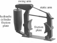
Fig.2 The structure of hydrauIic brakes
2 Establish the mathematical model of lifting mechanism
The design parameters of the 10t bridge crane are shown in Table 1,motor was selected as 11 kW YBZPE built-in brake motor,high speed shaft of the crane used the DYWZB200-30/30 hydraulic brake.Drum shaft adopts BBB50-13.8 band brake and the reducer was chosen as K4SH8 cylindrical gear reducer.

TabIe1 Lifting mechanism design parameter tabIe
Establisha quality-spring-quality equivalent model to the input shaft as a benchmark,as shown in Fig.3,J1is the rotational inertia of the motor rotor and the high-speed shaft brake,J2is the rotational inertia of the high-speed shaft brake and equivalent rotational inertia of gear the transformation on the shaft I in reducer;J3is equivalent rotational inertia of drum and promoted weight transformation on the shaft I,J制is the rotational inertia of the DYWZB200-30/30brake. Therefore,it could be evaluated directly by using mathematical method and cannotbe directly calculated by Pro/E software which is used to establish the threedimensional solid model,and the rotational inertia of the rotating components could be automatically evaluated by using the software.

Fig.3 EquivaIent modeI diagram
2.1 The rotational inertia calculation of the drum and weight
The rotational inertia of the drum:

Where,ρ is the density,ρ=7 850
The transformed rotational inertia to the motor shaft is:
J卷=0.004 06 kg·m2
The transformed rotational inertia of heavy lifting is:
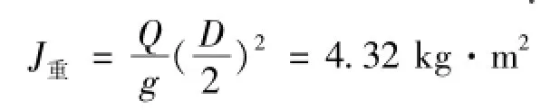
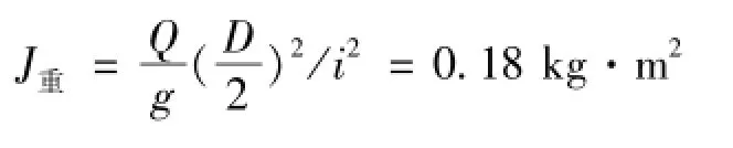
Where,Q is the weight and the value is 10 t,g is the gravitational acceleration,D is the drum diameter. The transmission ratio is i,the J重conversion to the motor shaft,and the value is as follows:
2.2 The equivalent rotational inertia automatic calculation of reducer
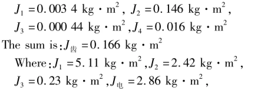
Using Pro/E software to draw K4SH line of cylindrical gear reducer each shaft components,rotational inertia of each axis could be calculated separately,the transformed rotational inertia of each gear to the motor shaft are as follows:

The resistance torque conversion to the input shaft T2=510 N·m;
The braking torque conversion to the input shaft T= 900 N·m.
3 Calculation and simulation ofthe brake arrangement in high speed shaft
Braking torque to the brake 2 and brake 3 at the same time,each bearing 450 N·m braking torque. Mechanical system based on the input shaft,its equivalent model is shown in Fig.4.During the brake process,motor will stall and the braking torque T becomes the resistance torque.
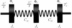
Fig.4 The equivaIent modeI diagram of high speed shaft braking
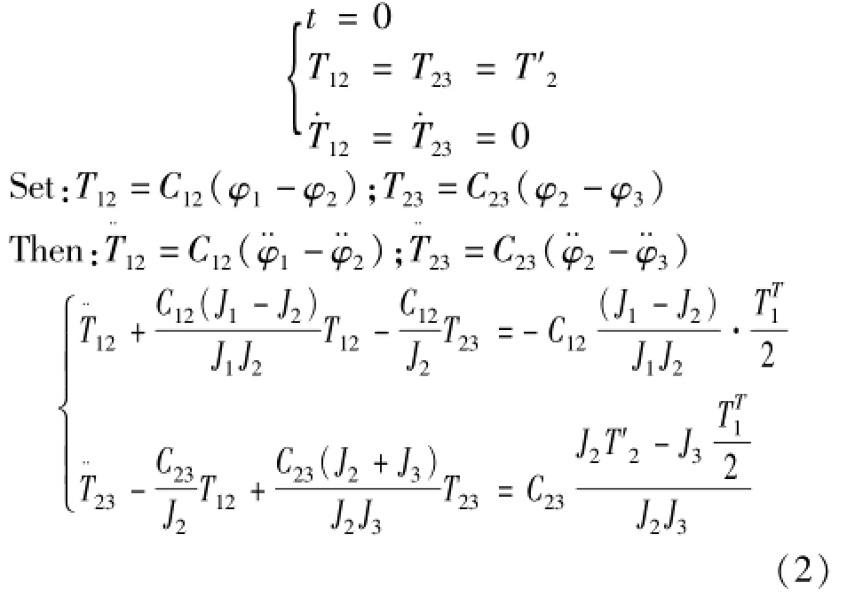
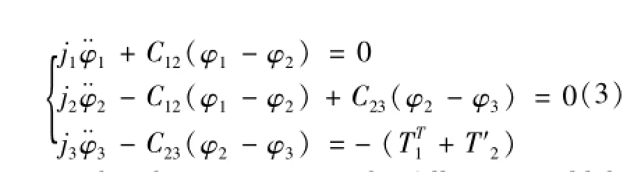
At this time,the system motion differential equations could be established as follows:

The initial condition is:
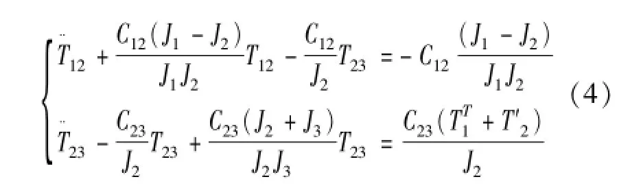
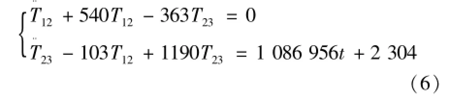
Substituting the value calculated that:

Runge-Kutta method for solving differential quations:

The Matlab program was used to solve the above differential equations and the procedure is as follows:
function zhidong
clear;clc
x0=[0;530;0;530;0];
[t,x]=ode45(@zhidong,[0,0.2],x0);
plot(t,x)
function dx=zhidong(t,x)
dx=[1;x(3);363*x(4)-540*x(2)+172 211;x(5);103*x(2)-1190*x(4)+524434];
From the Fig.5,it could be seen:
T12max=510 N·m,T23max=530 N·m
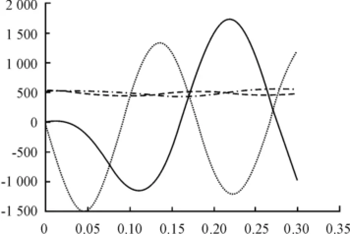
Fig.5 Time-domain diagram of torque
4 Calculation and simulation ofthe brake arrangement in low speed shaft
Braking torque is applied to the drum 3 and themechanical system is based on the input shaft,the equivalent model is shown in Fig.6.The differential equations of motion could be obtained as follows:
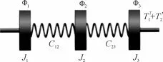
Fig.6 EquivaIentmodeIdiagramofIowspeed shaft braking
From the above equations,the following could be obtained.
If the data are substituted,one could obtain the following:

The solution of the above differential equations are similar to the previous example,and the calculation resultsare shown in Fig.7.
T12max=1 920 N·m,T23max=3 200 N·m

Fig.7 The caIcuIation resuIt of Iow speed shaft braking
If the time characteristic of braking force is considered,the braking time t could not exceed 7 times of the free vibration period.If the braking time is ti, during braking process,the braking torque TT′1could be gradually added.
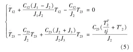
Substitute the data into the above equation,the differential equations of motion become:
The solutions of the above differential equationsare similar to the previous example,and the calculation resultsare is shown in Fig.8.


Fig.8 The caIcuIation resuIt of Iinear braking torque
5 Conclusions
Fortheabove-mentionedthreebrakedesign schemes,set the brakes to the high speed shaft,the brake torque is small and the size of brake is small as well.However,high speed shaft brake due to the shaft I has negative elastic dynamic load T12,the torque by the shaft I could suddenly reverse,so that to make the gear transmission device,due to the existence of the tooth side gap,inevitably impact.
Set the brakes to the low speed shaft,the braking torque on the output shaft,shaft I,shaft II loading is greater,but it will not reverse.If the braking time is considered,make the system in the process of braking is not sudden loading,but gradually loading.The maximum dynamic load on shaft I and shaft II are small axis,but the braking torque on the output shaft,the transmission ratio of transmission system is i,the braking torque that the output shaft required should be needed.For iT1,the size of brake is larger.
In order to minimize flywheel torque of brake mounted on a high speed shaft,the lifting mechanism of motor could be started quickly to reach the rated speed.If a brake is arranged in the high speed shaft,the brake should be installed at the end of the reducer shaft,rather than on the motor shaft,to ensure safe and reliable braking.At the same time,in order to make the mechanism compact layout,it should strive to axial size of the smallest.
Acknowledgements
This paper is supported by National Natural Science Foundation of China(No.50775155)and the Henan province Education Department science and technology key projectFundation(No.12A460004).
[1]Zhang Xin,Xu Zili,Luo Xingjian,Zhao Juan.Research on Key Technologies of Interactive Crawler Crane Simulator[J].Computer simulation,2012(11):386-390.
[2]Deng Qian-wang,Li Xiao,Gao Li-kun.Research and Application of Crane Motion Simulation Technology in Virtual Scene[J].Computer Engineering and Design,2013;34(11):3961-3965.
[3]Chen Gang,Cui Zhuang-ping,Zeng Yang.Research on Real-time Motion Simulation of Multi-body System Based on Physics Engine[J].Journal of System Simulation,2013:25(Suppl.):167-172.
起重機(jī)起升裝置制動器的設(shè)計與仿真
趙敬云1*,程雪利1,李 強2,趙筱赫1
1.河南機(jī)電高等專科學(xué)校,河南新鄉(xiāng) 453002
2.新鄉(xiāng)市起重設(shè)備廠有限責(zé)任公司,河南新鄉(xiāng) 453002
制動器的設(shè)計與選型是橋式起重機(jī)生產(chǎn)過程的重要環(huán)節(jié),制動器的位置與布局關(guān)系起重機(jī)的運行平穩(wěn)與安全。以10 t橋式起重機(jī)為設(shè)計對象,對起升機(jī)構(gòu)進(jìn)行動力學(xué)分析,建立了數(shù)學(xué)模型,計算了數(shù)學(xué)模型所需的轉(zhuǎn)動慣量;并對制動器不同布置方案進(jìn)行了計算與仿真,利用Matlab軟件得到了制動器制動的最大力矩,分析得出了制動器設(shè)計的最優(yōu)方案。
制動器;起重機(jī);動力模型
10.3969/j.issn.1001-3881.2015.12.021Document code:A
TH215
11 January 2015;revised 13 March 2015;accepted 15 April 2015
猜你喜歡
河北畫報(2020年8期)2020-10-27 02:54:06
現(xiàn)代裝飾(2020年7期)2020-07-27 01:27:42
流行色(2020年1期)2020-04-28 11:16:38
電子制作(2019年19期)2019-11-23 08:41:36
電子制作(2019年15期)2019-08-27 01:11:50
電子制作(2019年7期)2019-04-25 13:18:16
藝術(shù)啟蒙(2018年7期)2018-08-23 09:14:18
海峽姐妹(2017年7期)2017-07-31 19:08:17
Coco薇(2017年5期)2017-06-05 08:53:16
商周刊(2017年26期)2017-04-25 08:13:04
- 機(jī)床與液壓的其它文章
- Comparative study between the single frequency and synchronous double frequency induction hardening technique for gear
- Finite element simulation of different surface micro-pits textures cutting tool strength based on ANSYS/Workbench
- Design of SMA actuator of stem structure for flower robot
- Research and optimization on the venturi tube dynamic throttling element of new flowmeter
- Study on the defects and improvement of sequential function chart
- Design of quality traceability system for a kind of electromechanical products based on OPC