Optimization of One-Plane Packet Loss in IP Bearer Networks
2010-09-08 10:31:56
ZTE Communications 2010年2期
(Mobile Product Support Center of ZTE Corporation,Nanjing 210012,P.R.China)
In a mobile Softswitch system,the Mc interface refers to the interface between the gateway Mobile Switching Center Server(MSCS)and Media Gateway(MGW).The transmission protocol of the interface can be based on IP or Asynchronous Transfer Mode(ATM).In practice,the IP-based bearing mode is most commonly used in networks.
Since the MGW sometimes functions as the signaling gateway,the transported controlling messages between MSCS and MGW in the IP bearer network include H248 signaling of the Mc interface,as well as interface-A signaling for the Base Station System Application Part(BSSAP)/Signaling Connection Control Part(SCCP)and inter-office signaling for the ISDN User Part(ISUP)/Telephone User Part(TUP).Mobile Application Part(MAP)/SCCP signaling for the Mobile Switching Center Mobile Application Part(MSCMAP),Visitor Location Register Mobile Application Part(VLRMAP),and Home Location Register Mobile Application Part(HLRMAP)is required.
Therefore,the IP bearer network is necessary and important for the normal running of the Softswitch system.
The IP bearer network is generally designed in a dual-plane mode.Therefore,the interruption of any plane should not affect the Softswitch service.However,in practice,when one-plane packet loss occurs in the IP bearer network,the Softswitch service is severely affected with symptoms of coupling congestion,coupling interruption,and low connection ratio.
This paper takes the ZXWN CS system as an example to analyze one-plane packet loss of the IP bearer network from the viewpoint of Softswitch.It also proposes a solution for network planning and optimization.
1 Active/Standby Access Mode and LoadBalancing Access Mode
In the early stages of replacing traditional switching devices with mobile Softswitch devices,(when the universal IP bearer network was not accessible),a dedicated IP bearer network mode was used,providing point-to-point IP bearing.With the improvement of the IP bearer network,Softswitch devices were implemented in the universal IP bearer network[1].
When Softswitch devices access the IP bearer network,two typical networking modes are used:active/standby access mode,and load balancing access mode.
The active/standby access mode has the following features:
(1)At the Softswitch side,one pair of Signaling IP Interface(SIPI)boards are installed.Each board provides one Fast Ethernet(FE)interface connected to two L2 switches,and then connected to two Customer Edges(CEs).
The function of the L2 switch is to ensure the independent implementation of the SIPI active/standby switchover,and Virtual Router Redundancy Protocol(VRRP).When a certain CE supports L2 interface,the L2 switch will not be configured independently.
(2)The interface board at the Softswitch side uses the active/standby working mode.CE enables VRRP for the softswtich side.
(3)Fault detection between the SIPI and CE is implemented independently.The basis of SIPI active/standby switchover detection is the port status between the SIPI and L2 switch.The basis of switchover detection in the CE is the heartbeat message between CEs.
(4)Normally,in the active/standby mode,as shown in Figure 1,one transmission channel(active channel)is used between MSCS and MGW.
Features of the load balancing access mode include:
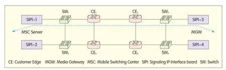
Figure 1.Networking example of active/standby mode.
(1)One pair of SIPI boards are configured at the Softswitch side.Each board provides an FE interface accessing the CE,or accessing the CE after switch convergence.
(2)The interface board at the Softswitch side uses the load balancing mode.CE also uses the load balancing mode.
(3)Bidirectional Forward Detection(BFD)is performed between SIPI and CE.
(4)Normally,as shown in Figure 2,between the MSCS and MGW using load balancing mode,two transmission channels can be used.
2 IP Bearer Network One-Plane Packet Loss in Two Networking Modes
(1)In the active/standby mode,the service is carried by the active transmission channel only.The symptoms of one-plane packet loss in the bearer network are as follows.
The Softswitch service is not carried by the standby channel,so when packets are lost in the standby transmission channel,the service is not affected.The Softswitch device cannot detect whether packets have been lost in the standby channel.
Softswitch services are carried by the active transmission channel,so when packets are lost in the active transmission channel,the service is affected and the impact is related to the packet loss rate.The Softswitch device can detect packet loss in the active channel but cannot control the switchover to the standby channel of the IP bearer network.
When the active channel is interrupted,the IP bearer network can detect the interruption and switch to the standby channel.When the packets are lost in the active channel,the IP bearer network cannot detect it and thus the service will not be switched to the standby channel.
Therefore,when the active/standby access mode is used,and packet loss occurs in one plane in the IP bearer network,optimization cannot proceed at the Softswitch side.
(2)In the load balancing mode,the service is carried by two transmission channels.The symptoms of one-plane packet loss in the bearer network are as follows.
When packets are lost in one transmission channel,only that channel’s service will be affected.At the same time,the Softswitch side can detect the transmission channel with packet loss and choose the better channel for data transmission.
Therefore,when the load balancing access mode is used,and packet loss occurs in one plane in the IP bearer network,optimization can proceed at the Softswitch side.
3 Optimization Solution to One-Plane Packet Loss of IP Bearer Network in Load Balancing Mode
According to the preceding analysis,when the active/standby access mode is used and packets are lost in the active transmission channel,the router does not provide the link quality detection function,and the route cannot be switched.As a result,the upper level service carried will be seriously affected.When the load balancing access mode is used,the upper level service will not be affected.
In practice,although the load balancing networking mode is used in some cases,when a transmission channel fails,the service carried is affected.The following are the key reasons:
(1)Route Configuration Mode of the Stream Control Transmission Protocol(SCTP)[2]Destination Address
At the Softswitch side,the route to the SCTP destination IP address should be configured.For the load balancing access mode,the common setting modes are as follows:
Route configuration mode 1:configure a route;select the interface address of one router for the next hop.Route configuration mode 2:configure two equivalent routes;select the interface addresses of the two routers for the next hop;the two routes are equivalent and they are valid at the same time.
Route configuration mode 3:configure two non-equivalent routes;select the interface addresses of the two routers for the next hop;the two routes are not equivalent.Normally,only the routes with higher priority are valid.When the route with higher priority is not available,the route with lower priority is valid.
Route configuration modes 1 and 3 are single next-hop modes.Compared to mode 1,a standby route is added in mode 3.Route configuration mode 2 is a multiple-next-hop mode.
(2)To Use SCTP Multiple Homing or Not

Figure 2.Networking example of the load balancing mode.
In the SCTP protocol,the definition of multiple homing states that"if multiple destination transmission addresses can be used as the destination address of one end,the SCTP end can be considered to be multiple homing.Moreover,the Upper Level Protocol(ULP)of the end can select one address as the primary channel of the multiple-homing SCTP point."This feature is the major difference between SCTP and TCP.
When SCTP multiple homing is not used,there is only one transmission address to the destination address.For route configuration modes 1 and 3,there is only one valid route to the destination IP address.When the packets are lost in the route,the SCTP transmission service is affected.For route configuration mode 2,if packets are lost in one route,the SCTP transmission service will be affected.
When SCTP multiple homing is used,there are two or more transmission addresses to the destination address.And between the two ends,there are two or more channels.For route configuration modes 1 and 3,different destination IP addresses can be transmitted over different routes.When packets are lost in one route,only the relevant channel is affected.If the channel is the primary channel of the SCTP,the transmission service of the SCTP will not be affected.For route configuration mode 2,all channels are transmitted over the two routes.As a result,when packets are lost in one route,the SCTP transmission service will be affected.
(3)Impacts of SCTP Congestion on Addressing
The above mentioned reasons(1)and(2)are for a single SCTP.In practice,the upper level service usually uses a pair of SCTPs to transmit data.Taking Message Transfer Part 3(MTP3)-User Adaptation Layer(M3UA)as an example,this paper analyzes the impact on the upper level service of SCTP failures.
In the M3UA protocol,the definition of fault resilience is"the capability that the signaling service re-routes to the alternative server process or application server process group when the current Application Server Process(ASP)is faulty or is unavailable.Fault resilience is also used to return to the previously unavailable application server process."
ASP contains the SCTP ends.When some SCTPs in the ASP group are faulty or unavailable,according to the protocol,the upper level service will not select the faulty SCTP.But when some SCTP is congested but not interrupted,the upper level service can select the congested SCTP.As a result,the service is affected.
4 Networking Optimization Suggestions
Considering the previous analysis,optimization suggestions for the mobile Softswitch and IP bearer network are as follows:
(1)Use the load balancing access mode:in the active/standby access mode,the forwarding plane or path cannot be switched and the NE has no initiative for switching.Therefore,the load balancing access mode should be selected.
(2)SCTP supports transmission quality monitoring:when the SCTP channel has multiple transmission paths,the transmission quality of each channel in the SCTP layer should be monitored and a path with better transmission quality automatically selected.
This function requires that a crossover node cannot exist in multiple transmission paths.Otherwise,when the packets are lost in the crossover node,the link quality of all transmission paths will decrease.
(3)Use the SCTP multiple homing configuration:each SCTP active channel and standby channel takes different routes and there is no crossover node.
By default,when the number of failures or re-transmission attempts of the active channel exceed 5(this parameter is configurable),switchover of the SCTP primary channel is performed automatically.

When transmission quality monitoring is supported,the SCTP can detect the transmission quality of each channel.When the transmission quality of the active channel is degraded but the channel is not interrupted,the SCTP can switch over the channel and automatically select the channel with better transmission quality.
(4)Optimize the SCTP congestion control:when the upper level service is dynamically selecting a route,the uncongested SCTP is automatically selected according to the SCTP congestion status.At the same time,the threshold of congestion reporting is set.Only when the threshold is exceeded,is the congestion reported to the upper level user,and the upper level user controls the congestion of the service traffic.
[1]YD/T 1194—2002.流控制傳送協(xié)議(SCTP)[S].2002.YD/T 1194—2002.Stream Control Transport Protocol(SCTP)[S].2002.
[2]YD/T 1192—2002.No.7信令與IP互通適配層技術(shù)規(guī)范——消息傳遞部分(MTP)第三級用戶適配層(M3UA)[S].2002.
YD/T 1192—2002.Technical Specification of Adaption Layer for No.7 Signalling Interworking with IP—Message Transfer Part(MTP)Level 3 User Adaption Layer(M3UA)[S].2002.

- ZTE Communications的其它文章
- ZTE Hosts IEEE 10G-EPON Interoperability Showcase
- ZTE and Innofidei Achieve Industry’s First Field IOT on Multiple TD-LTE USB Donglesin a Mobile Network Cell
- ZTE Sells World’s Fastest HSPA+28.8M Data Card with Greece’s COSMOTE
- A Study on the Standardization of Future Internet Architecture
- ZTE to Build IMS COre Network for China Mobile
- Bearer Network of the Future Internet