Cooperative Communication Protocols for Performance Improvement in Mobile Satellite Systems
2013-05-23 05:37:16AshagrieGetnetFlattie
ZTE Communications 2013年4期
Ashagrie Getnet Flattie
(Engineering Department,Ethio Telecom,Addis Ababa,Ethiopia)
Abstract A mobile satellite indoor signal is proposed to model performance of cooperative communication protocols and maximal ratio combining.Cooperative diversity can improve the reliability of satellite system and increase data speed or expand cell radius by lessening the effects of fading.Performance is determined by measured bit error rates(BERs)in different types of cooperative protocols and indoor systems(e.g.GSM and WCDMA networks).The effect of performance on cooperative terminals located at different distances from an indoor cellular system is also discussed.The proposed schemes provide higher signal-tonoise ratio(SNR)—around 1.6 dBand 2.6 dBgap at BER 10-2 for amplify-and-forward(AF)and decode-and-forward(DF)cooperative protocols,respectively,when the cooperative terminal is located 10 m from the WCDMA indoor system.Cooperative protocols improve effective power utilization and,hence,improve performance and cell coverage of the mobile satellite network.
Keyw ords cooperativecommunication;amplify-and-forward;mobilesatellite system;signal-to-noise ratio;maximal ratio combining
1 Introduction
M obile communication via satellite is an integral part of IMT2000 and UMTS[1].Unlike in a terrestrial cellular network,transmission in a mobile satellite network is constrained by available power[2].Satellite communication using land-based mobile terminals suffers from shadowing,multipath fading,and strong variations in the received signal power because the signal is reflected by buildings and/or terrain.Shadowing of the satellite signal is caused by obstacles,such as buildings,bridges and trees,in the propagation path and results in attenuation over the entire signal bandwidth[3]-[6].More than 80%of users are usually inside buildings,and it is a challenge to provide high-performance indoor coverage,especially in terms of higher data rates.It is much more than a technical challenge;the business case must also be evaluated,and any solutions implemented must be future-proof.Nevertheless,buildings(in particular,high-rise office buildings)contain many potential users of telecommunications systems and could be significant sources of revenue if high-quality radio communication could bedelivered tothem.
Coverage and capacity problem can be expanded by installing more cellular base stations,but this requires more complex and costly hardware,not to mention expensive real estate on which to physically locate the base stations[7].In addition to this,applications for future ubiquitous communications will require wireless networks to have diverse network architectures and technologies[8].
Many sophisticated transmission technologies have been developed to improve the robustness and throughput of mobile systems.For example,multiple antennas can increase the capacity and reliability of mobile communications.Cooperative communication systems have also been developed as a lowcost alternative to multiple-input multiple-output(MIMO)systems[9].Over the past few years,cooperative communications has been one of the most widely explored topics.Cooperation involves generalizing the relay channel to multiple sources that have information to transmit,and these sources also act as relays for each other.The main idea behind cooperation is that each cooperating entity gains by means of the unified activity[10],[11].The benefits of cooperative communication in terms of link reliability and coverage extension have become better known within academia and the telecommunication industry over the past few years[12].With cooperative communication,most of the benefits of MIMOare also leveraged.Benefits such as array gain,diversity gain,spatial multiplexing gain,and interference reduction can be obtained without using conventional MIMO technology and without increasing expenditure in termsof transmission timeor bandwidth[13],[14].
This paper describes a cooperative communication scenario in a satellite and cellular system.MATLAB is used to analyze the bit error rate(BER)of different cooperative communication protocols used in this scenario.
When analyzing satellite-to-indoor channels,we can useeither empirical measurements or deterministic channel modeling methods,such as ray tracing.In order to attain good reception,it is crucial to know the propagation conditions inside a room[15].Link budgets are calculated in order to analyze critical factors in the transmission chain and optimize performance in areas such as transmission power and bit rate.This ensures that atarget quality of service(QoS)can bereached[2].
The cooperative setup is shown in Fig.1.In general,there are two main relaying modes decode-and-forward(DF)and amplify-and-forward(AF).In DF mode,the message received by thesourceisfully decoded,and thedetected symbolsareremodulated into the same or different alphabet.The resulting data is forwarded to the destination.In this mode,propagation of decoding errors may lead to a wrong decision at the destination.In AF mode,the relaying node simply amplifies the received signal subject to power constraints[10].
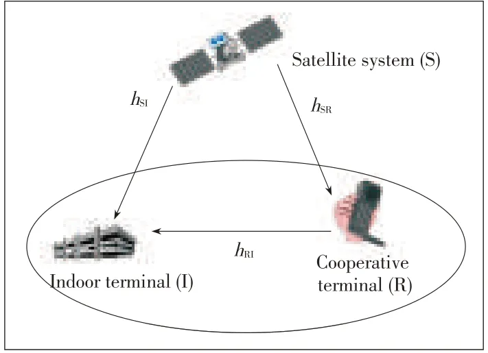
?Figure1.Basic cooperative communication system with asingle cooperativeterminal.
2 System Model
The basic cooperative communication system comprises a satellite system(S),cooperative terminal(R),and indoor terminal(I)(Fig.1).It is assumed that all the links use quadrature phase-shift keying(QPSK)modulation.Channel gains are given by h=(hSI,hSRand hRI).Several relaying protocols and MRC combining methods are examined to assess their effect on performance[16].Different numbers of cooperating terminals are used to examine the AF and DF transmission protocols.
Cooperative communication typically refers to a system where users share and coordinate resources it order to improve transmission quality.To achieve cooperative communication cooperating terminals can be specifically assigned portable relay nodes or other user terminals that temporarily form indoor system links.An indoor user must also act as a receiver for other cooperating usersor terminals.
In the first time slot,the satellite transmits the signal directly to the indoor destination and also to the cooperative terminal.In the second time slot,the cooperative terminal uses the AFor DFcooperative diversity strategy to retransmit the signal received fromthe satellite tothe indoor terminal.
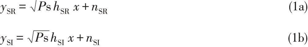
A fixed AF relaying protocol,often simply called an AF protocol,amplifiesthereceived signal and transmitsit tothe destination.In phase one,the satellite sends out the signal x with transmit power P s.The corresponding received signal ySRat the cooperative terminal and ySIat the indoor terminal can be written as[17],[18]:where P s is the transmission power at the satellite;x is the transmitted signal;nSRand nSIare the additive noise;and hSRand hSIcapture the effects of path loss,shadowing,and fading between the source and relay and between the source and destination,respectively.For simplicity,all channels are modeled as Rayleigh flat fading channels.The additive noise iswhite Gaussian noisewith zero-mean and variance N0[19].
In phase two,the satellite remains silent while the cooperative terminal amplifies the received signal and forwards it to theindoor terminal with transmit power Pcoop.Thereceived signal at thedestination can bemodeled as[16],[17]:

where q(.)depends on which processing is implemented at the cooperativeterminals.
2.1 Maximum Ratio Combining Output SNR
The maximum ratio combining(MRC)is an optimal combining technique with only linear complexity[7].MRC provides the best possible performance by multiplying each input signal with its corresponding conjugated channel gain MRC is based on the assumption that channel attenuations and phase shifts areperfectly known[20].
Using MRC at the destination node and based on(2),the total signal-to-noise ratio(SNR)given byγ=C/N,from the i th cooperative terminal is[21]:
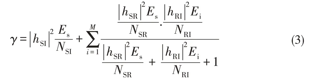
where hSI,hSRand hRIare independent complex Gaussian distributed channel coefficients of the source destination,sourcerelay i,and relay i destination channels,respectively.ESand Eiaretheaverageenergy transmitted at thesourceand i th cooperative node,respectively.These can also be considered as the transmission power,assuming that each transmission has unit duration.Tosimplify:
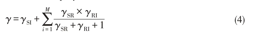
Assuming all cooperative terminals have thesame characteristics;γSI=γSRin(4):
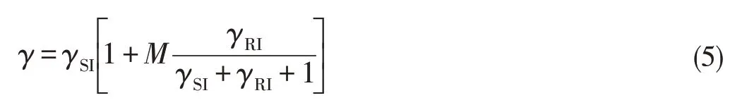
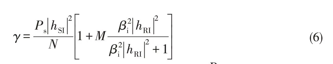
where β2ii th relay amplifier gain;the noise variance N=KTsysBs;Psis the satellite downlink power,Pcoopmaxisthecooperativemaximumpower,and M isthenumber of cooperativeterminals[23].
2.2 Cell Coverage
If we assume that the cooperative terminal is d km fromthe indoor system,then
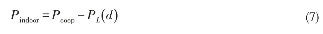
where PL()d is the mean path loss at the distance d km,Pcoopis theaveragepower transmitted by thecooperativeterminal,and Pindooristheaveragepower received at theindoor system(in decibels)[24],[25].Coverage and required average received power areinversely related toeach other.
3 Basic Principles of Satellite Communication
Every satellite application becomes effective by building on the strengths of the satellite link[26].Terrestrial cellular systems also experience dynamic fading as the subscriber drives past buildings and trees,under overpasses,or into isolated locations where base stations cannot reach.This fading is very rapid because it is produced primarily by multipath propagation.The strongest signal that is received may at times be a reflected signal off of one or more buildings[26].QoScan be expressed in terms of BER performance,which depends on the carrier-to-noise(C/N0)density ratio,and service reliability can be expressed in terms of service availability[27],[28].
Link budgets are calculated in order to analyze critical factors in the transmission chain and optimize performance in areas such as transmission power and bit rate.Link budgets also ensure that a QoStarget can be reached[2],and often help determine the ratio of carrier power to noise power at the receiver input.Thisratio is denoted C/Nor CNR[29].
In the case of fading in the downlink,the downlink C/N is(8)[2],[5],[30]:
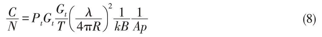
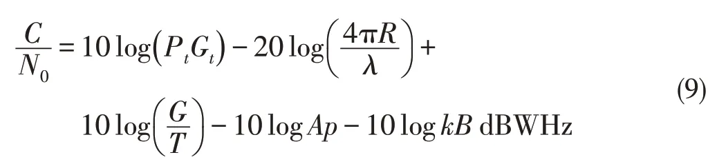
or expressing(8)in decibels:where N0is the one-sided noise power spectral density(dB/W/Hz-1)and is equal to N-10log,and-10log Ap istheatmospheric attenuation in decibels.
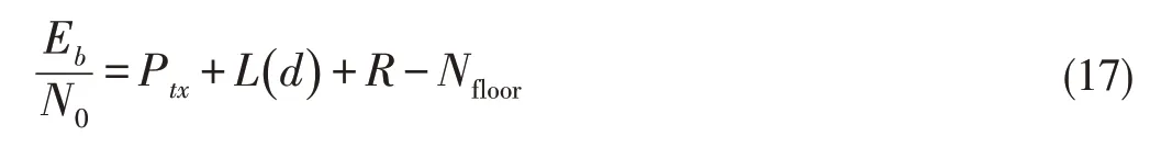
Equation(9)is valid for both the uplink and downlink.In the downlink,ERIPrefers to the satellite transmission and G/T refers to the Earth station or mobile terminal.G/T is the ratio of receiver antenna gain to system noise temperature,in dB/K,measured at the input to the receiving system[31].A significant condition in digital satellite link design is to ensure that Eb/N0is sufficiently large to guarantee that the BER performance criteria are met.The relationship between C/N and Eb/N0is[32]:
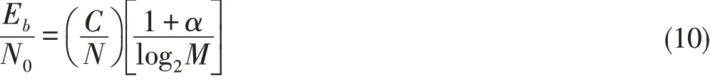
whereαisthechannel filter roll-off factor,and M isthepossible valuesor signals the phase of the carrier takesin a modulation scheme.
The relationship between C/Nand SNR is:
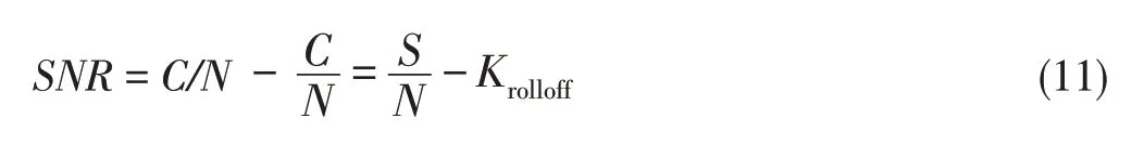
where Krolloff(assumed in DVB-S)is-0.3977 dB.The minimum mean received signal(carrier power)to noise spectral density
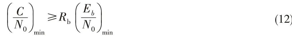
is related to the bit rate Rbvia[33],[34]where Eb=energy/bit(W),N0=noise energy density(W/Hz),and Rb=bit rate(bit/s).
35.He fell upon him and ate him up: The cat tricks the gullible ogre into transforming into small prey so he can easily kill him. Ogres and giants are often easily outwitted in fairy tales by tricksters, such as in The Brave Little Tailor. In other versions of the tale, the cat convinces the ogre to hide, such as in an oven, and then burns him up like the witch in Hansel and Gretel.Return to place in story.
3.1 Estimating SNR Using DAF
To calculate the SNR using DAF,the BER of the link must be calculated first and translated into an equivalent SNR.BER of onecooperativelink can becalculated as[20],[35]:

BERperformancefor a QPSK modulated signal isgiven by

where Q(.)isthe Gaussian-Qfunction.
4 Indoor Channel
The satellite to indoor propagation channel depends heavily on the layout and material properties,i.e.the construction materials used for walls,windows and ceilings,of the building where the receiver is located[36].Either empirical measurements or deterministic channel modeling methods can be used to analyze satellite-to-indoor channel.In order to achieve a good reception it is crucial to know the propagation conditions inside a room[15].In this study,the log-distance path-loss model[37],[38]is considered.The log-distance path-loss model isasite-general model,and thereceived power decreaseslinearly with distanceon alogarithmic scale:
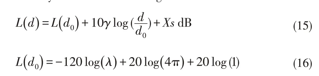
where L(d0)is the path loss at the reference distance(usually taken to be the(theoretical)free-space loss at 1 m);γis the path-loss distance exponent;and Xs is a Gaussian random variablewith zeromean and standard deviation ofσdB.
When Rayleigh fading is applied on a per-bit level,given by R,theenergy per bit tonoisepower spectral density ratiois
This empirical model takes into account the effects of shadowing by introducing Xs,which describes the statistical character of slow fading within the indoor link and,as a random variable,satisfies the long normal distribution with a standard deviation ofσin decibels[37],[39].
5 Simulation Assumption
Table 1 shows the key parameters for calculating and simulating SNR,C/N,Eb/Nb,and cell coverage.
6 Analysis of Simulation Results
In this section,we investigate the effect of cooperative partners on the SNR for each of the channels involved in cooperative cooperation.That is,we investigate satellite to indoor channel,satellite to cooperative terminal channel,cooperative terminal to indoor channel,and satellite to cooperative terminal to indoor system channel when the AF and DF cooperative diversity schemes are used.The results are expressed as BER versus total SNR at the indoor terminal and cell radius and are given asapercentage.
BERand equivalent percentage in cell coveragearethemetrics used to test overall system performance in two different cellular networks.One network is GSM at 900 MHz and the other is a 3G/WCDMA network at 2100 MHz.Direct transmission fromsatellite to indoor terminal is simulated,and cooperative transmission using Rayleigh fading channel models and log-distance path loss model are also simulated.The results of all these simulations are compared.Computation was done with MATLABusing QPSK modulation schemes.
Fig.2 shows that with AFand DF,cooperative relaying provides gains of approximately 1.5 dB and 3.1 dB,respectively,over direct transmission at BER 10-3.Cooperative communication performs significantly better than direct transmission,and AF performs better than direct transmission.However,the best performance is achieved with the DF scheme because with AF protocol,thereisamplified noisein thetransmitted signal.
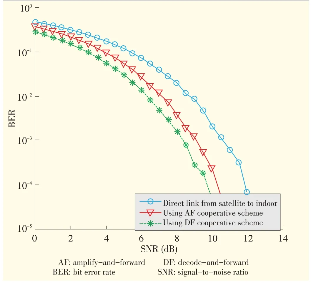
When transmitting directly from the satellite to indoor terminal,using the cooperative scheme with AF and DF results in performance that is 0.6 dB and 1.8 dB away,respectively,from that when the MRC scheme at a BER of 10-3(Fig.3).This is expected because the cooperation protocol effectively realizes a distributed receiver diversity.The direct transmission schemes require higher SNRs in order to provide the same performance as AF.This approach increases cell coverage inside the building because higher required average receiving power lowers coverage(and viceversa),asin(7),(15)and(17).
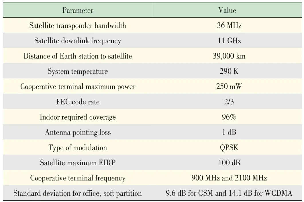
▼Table1.Simulation parameters
▲Figure 2.Direct transmission vs.different cooperative relaying protocols:Performancein terms of BERvs.SNR when a cooperativeterminal located 8m from the GSM indoor system.
▲Figure3.BERasafunction of SNRfor d=1000m and GSM900 MHz indoor terminal.
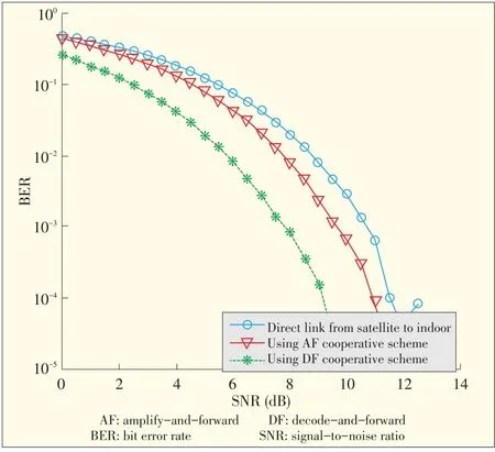
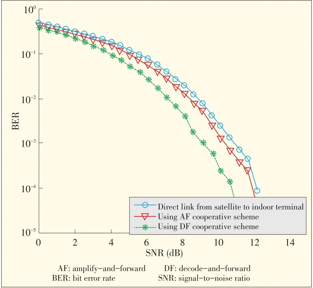
Fig.4 shows the BER as a function of SNR for different cooperative communication schemes.So far,the performance evaluation has only been done for basic satellite and cooperative scenarios.These scenarios will be extended to allow comparison for Eb/N0in WCDMA indoor terminal.When BER=10-3,SNRs are 10.8 dB,9.2 dB,and 8.6 dB for direct link from satellite to indoor,AF cooperative scheme,and DF cooperative scheme,respectively.The SNR values are calculated using(9),(10),(16),(18)and thevaluesin Table 1.
In the caseof DVB-S,we use(9),(10),(16)and Table 1 values.The corresponding C/N for direct transmission,cooperative transmission using AF protocol,and cooperative transmission using DF protocol are 11.2 dB,9.6 dB and 9 dB,respectively.The Eb/N0for direct transmission,cooperative transmission using AF protocol,and cooperative transmission using DF protocol are 9.6 dB,8 dB and 7.4 dB,respectively(assuming modulated QPSK signal and FEC to read Solomon=2/3).The target BER 10-3Eb/N0improvement is more than 1.6 dB.
One of our goals is to minimize the overall BER of the systems with the cooperative terminal located at different distances from the indoor terminal.Comparing Figs.4 and 5,at BER 10-3with AF protocol,the cooperative terminal at 1000 m requires 1 dB higher SNR in order to provide the same performance as at 10 m.Also from Figs.4 and 5 lower SNR is required when the separation distance between the cooperative and indoor terminal decreases.
7 Conclusion
In this paper,the simulation results of a cooperative communication system are described for different cooperative protocols.These results are compared with the performance results of a traditional wirelesssystems operating over a single link(direct transmission from satellite to indoor terminal).The BER performance of all cooperative protocols(using MRC combining type)isbetter than that of thedirect link.When the cooperative terminal is located 10 m from the WCDMA indoor terminal,the proposed schemes outperform in all cases,with approximately 1.2 dB and 2.1 dB gap at BER 10-3for AF and DF cooperative cases,respectively.Moreover,the position of the cooperative terminal affects overall system performance.The best performance is achieved when the cooperative terminal is located near the indoor terminal.At BER 10-2and with AF protocol,the cooperative terminal at 1000 m requires 1.4 dB higher SNR to provide the same performance at 10 m in a WCDMA network.Finally,cell coverage is increased by reducing the required averagereceived power.
▲Figure4.BERvs SNRwith a cooperativeterminal 10 m from the WCDMA indoor terminal.
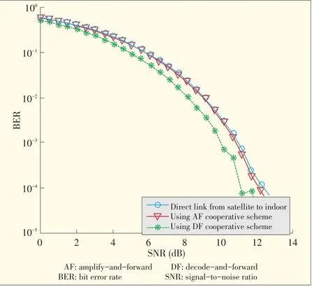
▲Figure5.BERvs SNRwith a cooperativeterminal at 1000 m(total path loss140 dB)from WCDMA indoor terminal.
Acknowledgments
I would like to thank my wife Dr.Alemnesh Woldeyes for her valuablecommentsand continuousencouragement.
- ZTE Communications的其它文章
- ZTE Achieves TM Forum’s Frameworx 12.0 Conformance Certification
- ZTE Contributed to Launch of 4G Network of BASE Company in Belgium
- 2014 International Conference on Information and Communications Technologies
- ZTE Communications Table of Contents,Volume 11,Numbers 1-4,2013
- Capacity Scaling Limits and New Advancementsin Optical Transmission Systems
- Virtualizing Network and Service Functions:Impact on ICT Transformation and Standardization