Design and application of attitude measuring device for DC power output filter circuit
2014-06-09 14:44:40HuanlingZHAO
機床與液壓 2014年3期
Huan-ling ZHAO
Guizhou Vocational Technical University,Guiyang 550023,China
Design and application of attitude measuring device for DC power output filter circuit
Huan-ling ZHAO?
Guizhou Vocational Technical University,Guiyang 550023,China
This paper introduces the working principle of the attitude measuring device for DC power supp ly circuit.The sensor output filter circuit of DC power supply circuit has been designed based on the working demand of sensitive element in the attitude measuring device.The direct coupling influence on the sensor output from the system power supply,as well as the actual working circumstance in engineering application,has been analyzed.Under the practical engineering application analysis of the circuit,the sensor in the attitude measuring device is able to work normally and avoid the dithering phenomenon of the system in zero position.The working requirements of the system have been well satisfied.
DC power supply,Filtering,Coupling
1.Introduction
As a measuring equipment to measure the roll angle and the pitch angle of a carrier at a low angular rate(less than 20°/s),the attitude measuring device calculates the system angle and the pitch angle through measuring the component of the gravity acceleration with the sensor and eliminating the influence of the roll angular rate at the same time.
In the practical application,the attitude measuring device is provided with a DC power supply mainly from the system,and the quadratic DC power supply of the device provides the working power supply for the sensor because of the limits of the system working environment.In order to improve the measuring accuracy of the roll angle and the pitch angle,the sensor uses the quartz flexible accelerometer to obtain the acceleration of gravity.The quadratic DC power supply of the attitude measuring device provides the working power supply for the accelerometer.According to the accelerometer servo circuit principle,direct coupling noise of the system power supply and the DC power supply circuit will have a rather obvious effect on the frequency and amplitude of circuit trapezoidal wave in the servo circuit,resulting in a large zero drift,which will directly affect the zero position output of the accelerometer,and eventually lead to the system output stability error.According to the actual working situation of the system,the attitude measuring device second-order low-pass filters the accelerometer output with signal processing circuit to reduce the noise produced by the accelerometer bandwidth during working at first.Then,for the direct coupling noise of the system power supply,the need of conditioning the DC power supply output and reducing the influence of which direct coupling noise results on the accelerometer zero output is necessary.Therefore,during the design process of DC power supply circuit,the design of DC power supply output filter circuit has considerable engineering application value for improving the zero position stability of attitude measuring device.
2.The circuit principle
DC power supply circuit isolates and filters the 27 V power provided by the system and provides the±15 V working power supply for the sensor on the accelerometer and other electronic components.For the±15 V power supply of the accelerometer,DC power supply circuit consists of a transient suppression circuit,a filter circuit,a DC/DC converter circuit and an output filter circuit.The schematic diagram of DC power supply circuit is shown in Figure 1.
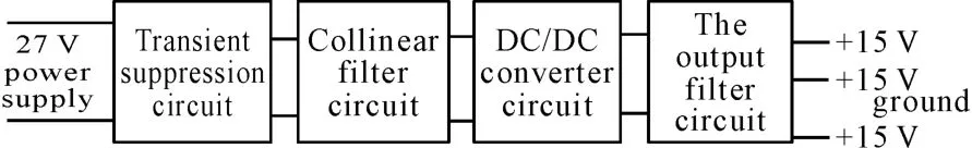
Figure 1.Schematic diagram of DC power supply
Transient voltage suppressor(TVS)is a high performance circuit protection device currently used over the world.With the same shape of ordinary diode,it also has the ability of absorbing up to several kilowatts power surge.The main characteristic is,in the reverse application conditions,when it is subjected to a surge,or other high energy transient overvoltage pulse,the impedance will immediately fall to an extremely low conduction value,allowing high current through and clamping the voltage at the predetermined level with a response time of only 10~12 ms,so that the precision components in the electronic circuit can be effectively protected.The measuring device utilizes TVS to manage the inlet of the 27 V system-provided power supply and absorb all kinds of transient interference there so that the electronic components in electronic circuit can be effectively protected.
Moreover,the electrical isolation can be achieved by converting the 27 V system-provided power supply into±15 V working power for acceleration via the DC/DCDC power supply module.In order to reduce the interference of27 V system-provided power supply acting on the DC/DC DC power supply module and the high frequency harmonic produced by switching power supply during working,the input end is facing to the high impedance(capacitor)and the output end to low impedance(DC/DC DC power supply module)at the inlet of filter circuit.In that way,impedance matching is realized and the best filtering effect is achieved.
In addition,outputting DC regulated power supply of the DC/DC DC module is with relatively large noise and has great influence on zero stability of the accelerometer,so the output filter circuit is usually used to connect the input end connected to high impedance(DC/DC DC power supply module output)and output end to high impedance(other active devices).
3.The circuit design
For the design of the accelerometer±15 V DC power supply circuit,the transient suppression circuit adopts a transient voltage suppression diode;the inlet filter circuit uses DC power supply filter,and DC/DC converter takes the DC/DC DC power supply module.The circuit is accomplished to meet the need of the circuit principle.Figure 2 shows part of the circuit design with transient suppression circuit,inlet filter circuit and DC/DC converter circuit according to the circuit principle.
As shown in Figure 2,V1 is the TVS SY5645A,N1 and N2 are the power filter JLC6101-3YBE,and G1 is the DC/DCDC power supply module FED20-24D15.
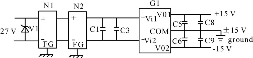
Figure 2.Part of DC/DC converter circuit
In the DC power supply circuit of the accelerometer,voltage drop is very small while the DC switching power supply module is turned on and the leakage current is also very small while the module is turned off,the energy consumption is close to zero and the power conversion efficiency can proceed up to 80%.
However,due to the high frequency working state of the switching power supply,which belongs to the strong interference source,current higher harmonic interference generated by the basic rectifier and peak voltage interference created by power conversion circuit are the main causes of its internal interference[1].In the attitude measuring device,the normal work of the accelerometer servo circuit will be affected.
Therefore,in order to reduce the coupling noise interference of DC power supply circuit’s power supply and the system power of the attitude measuring device,the output filter circuit should be designed according to the principle of the DC power supply circuit.
Firstly,the undesired signal occupies a certain frequency and space range;and for different interference signals,different measures should be adopted,one way is to shut it out,commonly with electromagnetic shielding technology to block the communicationchannel of interference signal or separate the interference signal and the working signal of the equipment in time,frequency and space range.The other measure is eliminating the interference signal with bypass and absorption method[2].
Secondly,as a low pass filter,the frequency response is the most common parameters for the performance of the filter.When a frequency response index is given,an appropriate filter must be chosen by first converting the required frequency response to the normalized low-pass form with 1 rad/s cutoff frequency,and then compared with normalized low-pass filter curves whose response and cutoff frequencies are also 1 rad/s after being normalized.After choosing a satisfying low pass filter,its value is transformed or normalized.The low-pass response mainly includes Butterworth response,Chebyshev response,linear phase response,synchronous tuning response,transient response,and elliptic function response[3].
Finally,on the basis of the accelerometer servo circuit of attitude measuring device,the output filter circuit is designed in DC power supply circuit.The output filter circuit is shown in Figure 3.
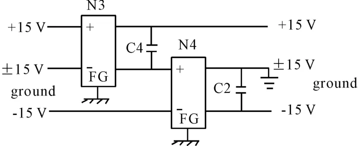
Figure 3.Output filter circuit
As shown in Figure 3,N3 and N4 are the power supply filter JLC6101-1DBE.Its internal circuit is shown in Figure 4.
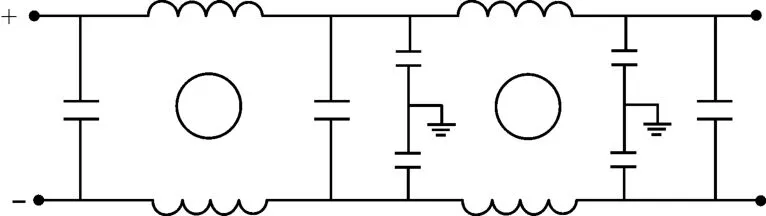
Figure 4.JLC6101-1DBE internal circuit
The working current of the accelerometer IOis 30 mA.As the switching power supply ripple current is 20%of the output current,the ripple current I is:

I is the ripple current(mA),and IOis the working current(mA)of the accelerometer.The working voltage of the accelerometer VOis 15 V and the ripple voltage V(mV)is:

V is the ripple voltage(mV),and VOis the working voltage(mV)of the accelerometer.
Then the capacitance impedance ESR is:

The working frequency of the switching power supply module is 45 kHz.The capacitors C2 and C4 are chosen with 10μF.
4.The analysis of the circuit application
As the system turns on and works at zero position,the 27 V power supply provided to the attitude measuring device is 25 V DC with 80 mV AC noise(peak-to-peak value).An oscilloscope is used to monitor the AC noise and the result is shown in Figure 5.The abscissa represents time(μs)and ordinate shows voltage amplitude(mV)of AC noise.
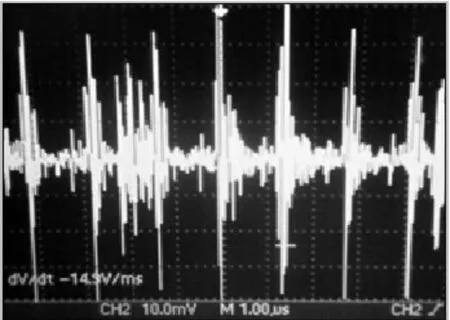
Figure 5.AC noise output of27 V system-provided power supply
If the output filter circuit is not added into the DC power supply circuit of attitude measuring device,when the system starts up,there is slight jitter,and the pitch angle and roll angle outputs of attitude measuring device show a jump about 0.2°.Monitoring the accelerometer zero output with an oscilloscope,it can be found that AC noise of the accelerometer at zero position is about60 mV and a low frequency noise of 10 K and 2 mV appears at the same time.AC noise of the accelerometer is shown in Figure 6.The abscissa represents time(μs)and ordinate shows voltage amplitude(mV)of AC noise.
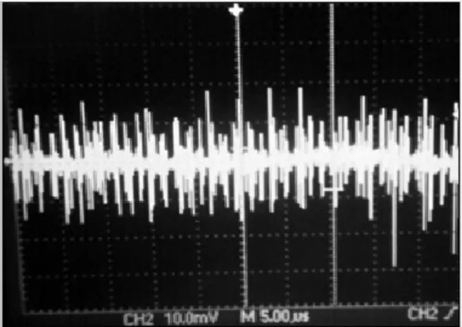
Figure 6.AC noise output of the accelerometer(without output filter circuit)
When the output filter circuit is not added into the DC power supply circuit of attitude measuring device and the system starts up,jitter does not appear and the system works well[4-6].Monitoring the accelerometer zero output with an oscilloscope,it can be found that AC noise of the accelerometer at zero position is about only 30mV,and no obvious low frequency noise turns up.Figure 7 shows AC noise of the accelerometer with output filter circuit.The abscissa represents time(μs)and ordinate shows voltage amplitude(mV)of AC noise.
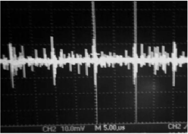
Figure 7.AC noise output of the accelerometer(with output filter circuit)
According to the differences between Figures 6 and 7,it is obvious that,except the DC/DC power supply module switching frequency noise,the amplitudes of other accelerometer AC noise outputs decrease significantly with the output filter circuit.At the same time,the low frequency noise with the frequency of 10 K and the amplitude of 2 mV is effectively curbed;the pitch angle and the roll angle of attitude measuring device output run steadily and the system works normally.Therefore,the output filter circuit of DC power supply can satisfy the actual need of the system.
5.Conclusion
From the analysis and application above,the coupling noise of the system power supply and DC power supply of the attitude measuring device has a considerable influence on the output of the accelerometer.After passing the output filter circuit,the output noise of the accelerometer has been effectively controlled and the low frequency signal which leads to system jitter can be restrained.As a result,the system can be guaranteed to work normally in practical engineering applications.At the same time,considering the low system working frequency and in order to speed up the attenuation of the output disturbance signal in the stopband region,adding the voltagecontrolled second-order low-pass filter at the output end of the acceleration can suppress the high frequency signal and effectively ensure the stability of the system.
[1] Hou Zhenyi.DC switching power supply technology and application[M].Press of Electronics Industry,2006(4):208-209.
[2] Tian Liang,Wang Yao,Huang Zhengjin,et al.Integrated electronic beam design and practice[M].Press of Southeast University,2002(3):262.
[3] Arthur BW,Fred JT,Ning Yanqing,et al.The electronic filter design[M].Science Press,2008.
[4] Zhao Huanling.Research and application of dynamic measurement error of the system angle[J].Guizhou science,2013(5):36-38.
[5] Zhao Huanling,Dai Hongbing.Shift delay attitude angle measurement study error compensation based on inertial technology MEMS[J].Guizhou Science,2012(1):70 -72.
[6] Zhao Huanling,Dai Hongbing,Xing Zhonghe.Quartz flexure beam impulse response analysis[J].Modern Machinery,2009(1):21-22.
姿態測量裝置直流電源輸出濾波電路的設計與應用
趙煥玲?
貴州職業技術學院,貴陽 550023
介紹了姿態測量裝置直流電源電路的工作原理,根據姿態測量裝置中敏感元件的工作需要,對敏感元件直流電源電路的輸出濾波電路進行了詳細設計,并結合工程應用中系統實際使用情況,分析了系統電源對敏感元件輸出產生的直接耦合影響。通過對電路在工程中的實際應用分析,姿態測量裝置敏感元件能正常工作,可避免系統在零位工作時的抖動現象,滿足系統的使用要求。
直流電源;濾波;耦合
TH824
10.3969/j.issn.1001-3881.2014.18.024
2014-05-03
?Huan-ling ZHAO,E-mail:zhao_zhl@163.com
猜你喜歡
工業設計(2022年8期)2022-09-09 07:43:20
軍民兩用技術與產品(2021年10期)2021-03-16 06:05:30
北京測繪(2020年12期)2020-12-29 01:33:58
裝備制造技術(2019年12期)2019-12-25 03:06:46
中學生數理化·八年級物理人教版(2019年9期)2019-11-25 07:33:02
中國洗滌用品工業(2019年4期)2019-05-11 09:27:34
中學生數理化·八年級物理人教版(2019年3期)2019-04-25 06:20:54
中學生數理化·八年級物理人教版(2018年3期)2018-05-31 08:52:45
數學小靈通(1-2年級)(2017年10期)2017-11-08 08:39:45
家庭影院技術(2017年9期)2017-09-26 03:41:45
- 機床與液壓的其它文章
- Developing deburring device based on burr formation principles*
- Experimental study on milling tool life for SKD11 steel and optimization of cutting parameters*
- Application research on three-phase inverter with space-vector pulse modulation*
- Glowworm swarm optimization algorithm merging simulated annealing strategy*
- Comprehensive obstacle avoidance system based on the fuzzy control for cleaning robot
- Implementation of wireless communication and real time control for CNC system of embedded CNC turret punch press*