Software development for on-machine measurement of large CNC gear shape*
2014-07-31 20:22:31XiaodongGUOMengxiangSUNWeiqingZHANGMingZHAO
機床與液壓 2014年2期
Xiao-dong GUO, Meng-xiang SUN, Wei-qing ZHANG, Ming ZHAO
The Key Lab of Automobile Parts & Test Technique, Ministry of Education, Chongqing University of Technology, Chongqing 400054, China
Software development for on-machine measurement of large CNC gear shape*
Xiao-dong GUO?, Meng-xiang SUN, Wei-qing ZHANG, Ming ZHAO
TheKeyLabofAutomobileParts&TestTechnique,MinistryofEducation,ChongqingUniversityofTechnology,Chongqing400054,China
According to the processing principle of large CNC gear shaper, the calibration principle and measuring principle of on-machine measurement were studied for large gear shaper machine. On this basis, CNC gear shaper on-machine measurement software was developed and embedded in the YKW51250 gear shaper of Tianjin No.1 Machine Tool Works. Measurement experiment on YKW51250 shows that the software algorithm is correct and the on-machine measurement software is reliable.
CNC gear shaper, On-machine measurement, Software development
1.Introduction
Large gears are not only widely used in mining, shipbuilding and other heavy machineries, but also an important part of national defense, astronomy and other precision machineries. Large gear’s precision has a great influence on the work performance of precision machinery. To obtain high-precision gears, gear measurement is essential.
Currently, most of the small modulus gears are measured by gear measuring center measurement, and the technology is very mature. But it is difficult to install and move large gear in the gear measuring center, because the large gear has big diameter and large inertia. Gear measuring center is unable to satisfy measurement requirements of large gears, and it is necessary to develop a professional measuring instruments for large diameter, large modulus gear[1].The method of on-machine measurement is mostly used in the large gear machine and the large grinding machine[2].Gear hobbing machine of Niles, Hofler company have developed the on-machine measuring software, and which is widely used in the market. However, measuring software of large gear shaper machine is almost empty in the country because of the special structure of the machine[3].According to the measuring principle of gear shaper, this paper describes software development of the gear shaper on-machine measurement. It is significant to improve machine precision of gear shaper.
2.CNC gear shaper on-machine measurement principle
Figure 1 shows the general structure of large CNC gear shaper with five axes.C-axis is the workpiece spindle, and drives gear and table rotation.C2-axis is the tool spindle, and drives tool rotation.C-axis andC2-axis linkage accomplishes tooth developed movement.Z-axis is the axial feed axis, and drives tool spindle up-down movement to achieve slotting movement.Z-axis andC,C2-axes linkage could achieve slotting helical gear.X-axis is the radial feed axis drive tool radially feed.X2-axis is the axis that move tool to avoid collision. Workpiece spindle C uses a circular or linear grating to achieve closed-loop control, because the positions of tool spindleC2, axial feed axisZand radial feedX-axis are required to be accurately controlled.
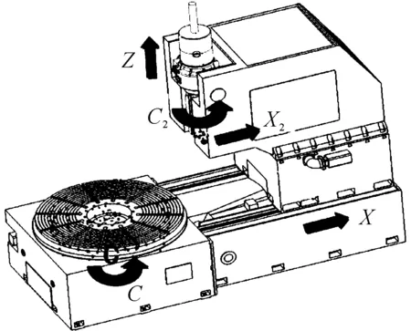
Figure 1. The structure of large CNC gear shaper machine
Currently, there are two main kinds forms of the a large gear machine measurement system: top-mounted and side-mounted. Top-mounted is measuring device positioned on the measurand, and which has small size and low costs. It is mainly used for smaller, low accuracy large gears whose measuring basis built on measurand is errors in gear. Side-mounted is measuring device positioned on machine or beside the machine, and it can measure many error terms and has high accuracy[4].
In this paper, the form of side-mounted is selected. The measuring device clamps on the tool spindle and the probe installs below the gear shaper cutter (to avoid the removing of the measurement tool when gear is measured). Touch trigger probe must be selected because the CNC system only receives switching signal, and which is controlled by gear shaper CNC system to measure. The form of measuring basis is on the machine instead of the measurand, and the measurement is convenient and efficient without removing the tool, and reduces costs by using CNC system itself[5].

(1)
the probe moves a fixed distance along theX-axis, and then theC-axis is rotated to touch probe again by CNC system. Then it touches three points in total, and records theC-axis rotation angleθeach time. According to the angle of rotation and Equation (2), it can confirm the standard ball center position that the coordinates of the three probes center transform into the same coordinate system.
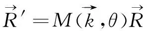
(2)
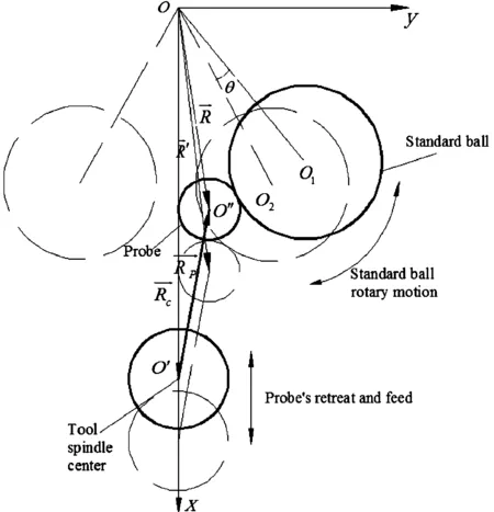
Figure 2. The schematic of probe calibration
(3)
(4)
Collecting point designed is one-sided when the gear is measured because of the big quality and the large inertia of the large gear, that is first the left tooth surface (or the right tooth surface), and then the right tooth surface (or the left tooth surface). System analyzes the error and judges accuracy class for the gear according to national standards after collecting the geometric information of the gear. Pitch measurement could confirm the size of each pitch by collecting the coordinate information of each gear tooth surfaces point. it can obtain the single pitch error and cumulative pitch error by comparing with the theoretical model[6].
Figure 3. The Schematic of measurement
The measurement of tooth profile is system that collects some points coordinate information along the direction of tooth height. The number of points are decided by the effective tooth profile and the pitchs of two points. The total tooth profile error and the tooth profile form deviation are obtained by fitting tooth profile compared with the theoretical tooth profile[7].
Helix measurement is that system collects some points coordinate information along the direction of tooth length. The number of points are decided by the effective helix and the pitch of two points. The total helix error and the helix form deviation are obtained by fitting helix compared with the theoretical helix.
3.The design of the software
According to the gear shaper’s theory of on-machine measurement, the on-machine measuring software is based on gear parameters to generate gear theoretical model, and based on probe parameters and calibration ball parameters to plan the path of probe calibration, the measurement path of gear pitch, tooth profile and helix; the software transmits data, processes and analyses error before generating the NC code of probe calibration and gear measurement to measure .
As the previously mentioned, on-machine measuring software must cooperate with CNC system, because the measuring device is driven by CNC system itself. For example, with Siemens 840D CNC system, the communication between on-machine measuring software and NC / PLC takes Sinumerik-COM port and OLE for Process Control of OEM software, and uses the storage capacity of NCDDE and DDE to achieve data-exchange. Regie application procedure can complete startup, initialization, and other works of the software. In this way, on-machine measuring software is inlayed in Siemens 840D CNC system by HMI Programming Package[8].
The measuring software is divided into five functional modules: document management, status monitoring, probe calibration, NC code generation and error analysis. A core algorithm library achieves the functions of five functional modules[9].
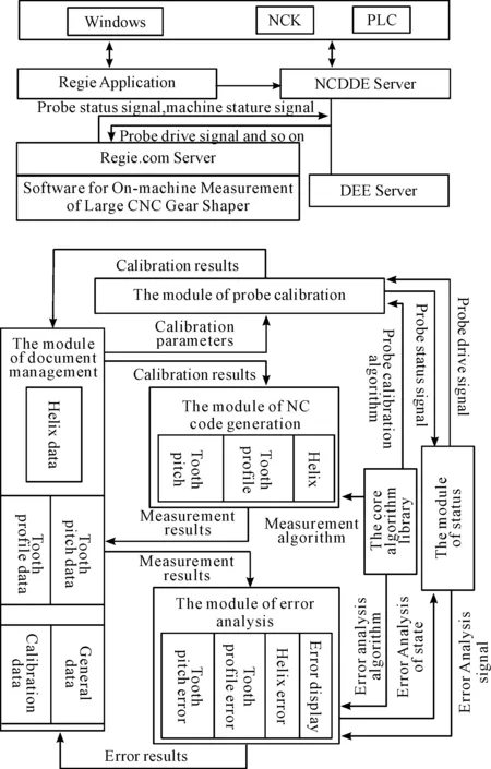
Figure 4. Software structure
The relation between the functional modules is shown in Figure 4. It depicts the function of the module and the linkages between each module and data-exchange in the entire process from inputting parameters to calculate the result of error.
The core algorithm library is responsible for the function of generating gear model, calculating the coordinate position of the probe in the process, probing calibration and gear measurement, and calculating the error value.
The module of document management is responsible for the function that can save the parameter of gear, probe, calibration ball, the result of probe calibration, and the measuring point coordinates. The data of probe calibration, gear measurement and error analysis are transmitted by this module.
The module of status monitoring is responsible for the communication between software and CNC systems, monitoring the position of probe, the measurement process, and that whether the channel and others are working properly.
According to probe parameters and calibration ball parameter, the module of probe calibration plans the path of probe calibration, generates the NC code of probe calibration, reads the measurement data, and saves calibration data in the document management module.
According to gear parameters, the results of calibration and measurement items, the module of NC code generation is planning the path of measurement, generating the NC code of measurement, and saving the measurement data in the document management module.
The module of error analysis reads the measurement data, calculates the error by calling the core algorithm library, shows the graphic of error, judges the accuracy class, and generates the measurement reports.
4.Interface design
According to the software modules, the software interface framework is designed as shown in Figure 5. The main interface of software can enter four functional interfaces: data management, probe calibration, measurement and analysis. Four functional interfaces connect channel which achieve specific functions interfaces. Whole system interface can achieve all the functionality of the software.
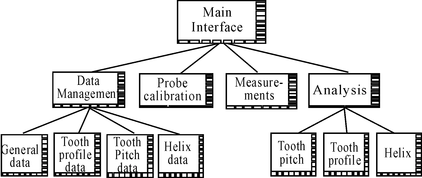
Figure 5. Interface framework
The function of response function buttons is designed because the software interface is not suitable for clicking mouse. The software interface of CNC system should have status display for CNC system such as channel display and machine status (alarm display, for example), the basic information displays such as the information of probe coordinate, the process of measurement, and the graphic of error. According to the framework map of interface and the design ideas of interface, CNC system interface is designed, as shown in Figure 6. It is divided into 8 horizontal softkeys, 8 vertical softkeys, status area, display area and prompt area. The horizontal softkeys achieve the function of menu for switching different functional interface. The vertical softkeys are responsible for specific functions and in response to different functions of software functions. The status area shows the information of current channel and status information. The display area shows visualize contents such as the graphic of error and the probe coordinate information. The prompt area is to prompt relevant information.
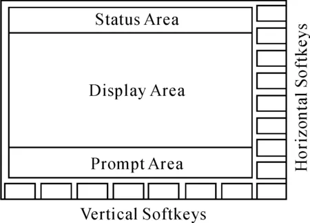
Figure 6. Software interface
5.The measurement process of software
After the gear manufacturing is completed, starting on-machine measurement software, inputting the parameters of gear, probe, calibration ball, clamping probe on the tool spindle, putting calibration ball in table rotation, starting calibration procedure to calibrate the probe, calculating calibration results, selecting the items to be measured, and generating the NC code of measurement, the measurement procedure is started to measure gear. This paper uses an example of pitch measurement to describe the process measurement gear.
Firstly, system judges whether the pitch measurement need to be carried. if not, project into the next item. if need, moving probe to the middle of alveolar with manual operation. Secondly, Probe and gear are driven by CNC system, and it is judged whether the measuring is successful. If not, exiting procedures. If successful, writing the C-axis angles to system. The probe will automatically retreats to a safe location and measures the next tooth surface on the same side, until the other sides of the gear tooth surfaces are measured after all of the same side tooth surface measurements are completed. Data are written in the system and the next item will be gone on after a successful measurement. Software analyzes the data, calculates and displays the error curve after all the measurement projects are completed. Finally, system prints the error curve and finishes the gear measurement.
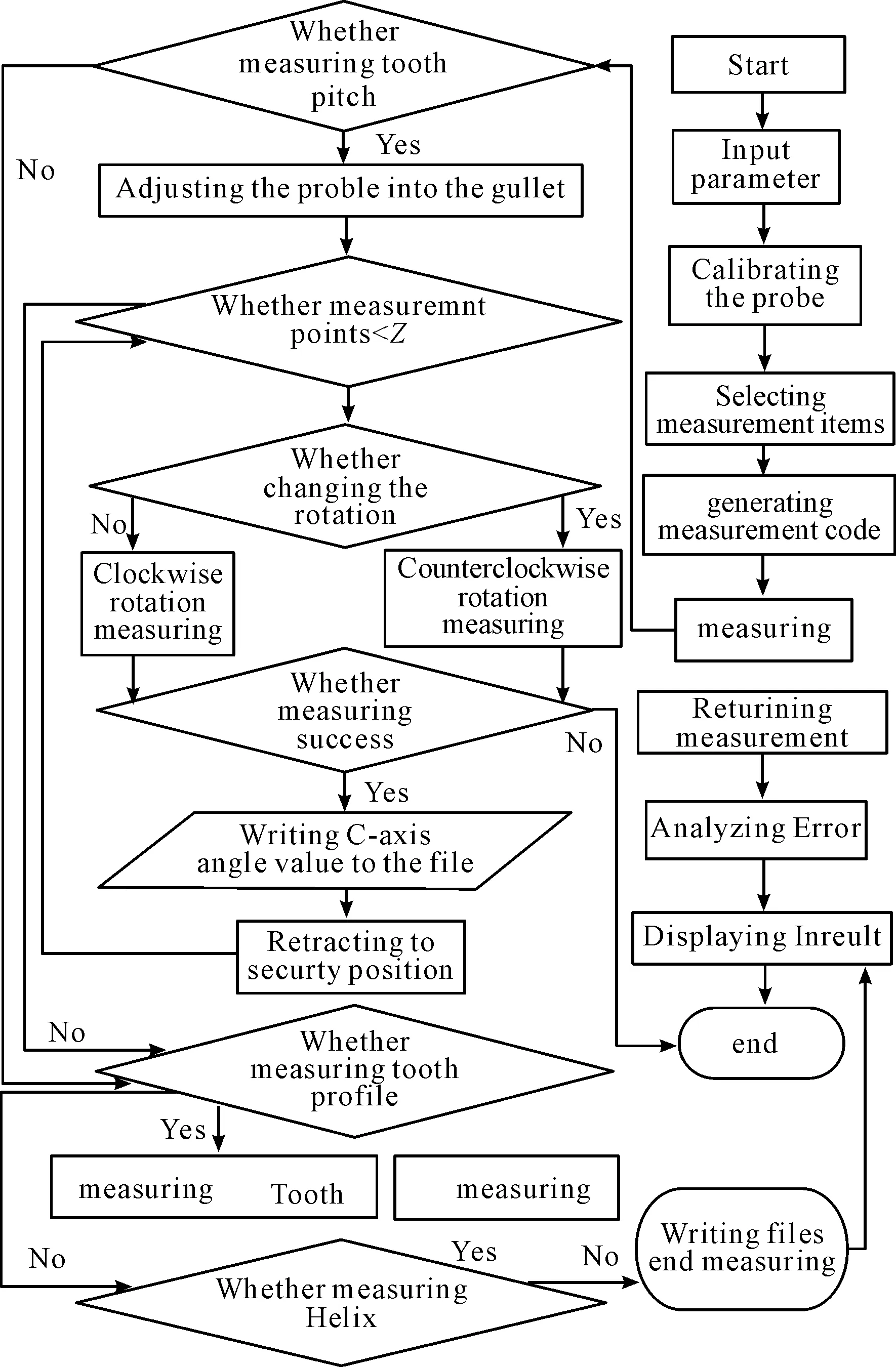
Figure 7. Measurement flow
6.Measurement experiment
In order to verify the correctness of the algorithm and the reliability of on-machine measurement software, CNC gear shaper on-machine measurement software is embedded in the YKW51250 gear shaper of Tianjin No.1 Machine Tool Works to test for measurement experiment. The basic parameters of the experimental gear are shown in Table 1. The probe is Renishaw LP2 and the radius is 5 mm. The radius of calibration ball is 100 mm.

Table 1 .The basic parameters of the experimental gear
The gear measurement process is shown in Figure 8.
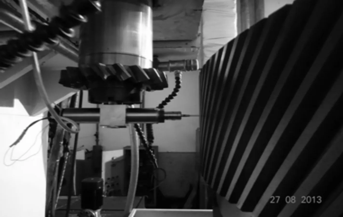
Figure 8. Gear measurement process
Measurement results are shown in Figure 9 to 11, The pitch error of left tooth surface is 17.3 μm, right tooth surface is -7.2 μm , and the precision grade is 7. The cumulative pitch error of left tooth surface is 209.2 μm, right tooth surface is 164.8 μm, and the precision grade is 8. The total tooth profile error is 22.7 μm, and the precision grade is 6. The tooth profile form deviation is 22.4 μm, and the precision grade is 7. The total helix error is 31.7 μm, and the precision grade is 7. The helix form deviation is 30.6 μm, and the precision grade is 8[10].

Figure 9. The pitch error
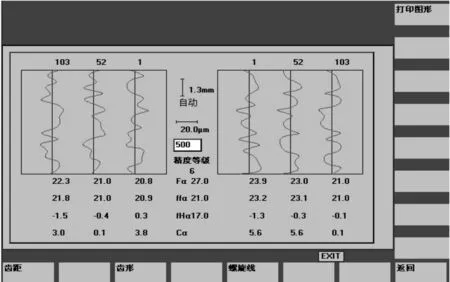
Figure 10. The tooth profile error
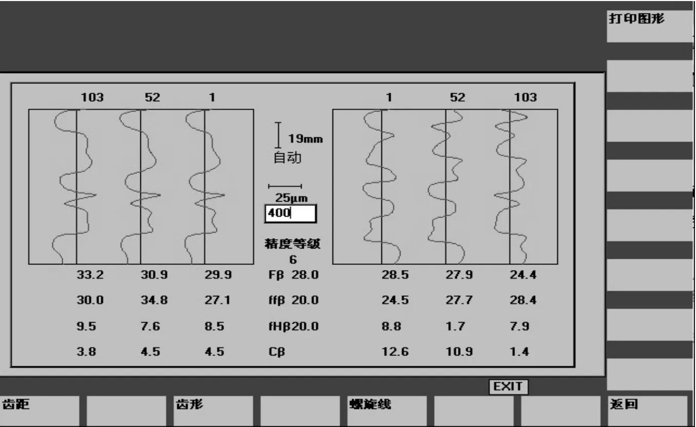
Figure 11. The helix error
7.Conclusion
According to the movement characteristics and the working principles, the probe calibration theory, measurement algorithms and error analysis methods of on-machine measurement are studied for the large gear shaper. A large gear shaper online measurement software is developed and embedded in Siemens 840D system with simple operation and high reliability. Software can measure the error of tooth pitch, tooth profile and helix for large gear. The correctness of algorithm and the reliability of on-machine measurement software are verified by measurement experiment. This paper has important guiding significance for developing the large gear shaper on-machine measurement software, and for improving the precision of large gear shaper.
[1] Mikoleizig G.How to inspect large cylindrical gears with an outside diameter of more than 40 inches[J].AGMA Technical Paper, 2001:1-18.
[2] SHI Z Y, LIN H, LIN J C, ZHANG B.Current Status and Trends of Large Gears Metrology.CHINESE JOURNAL OF MECHANICAL ENGINEERING, 2013.03
[3] Mikoleizig G.CNC gear inspection technology and new software solutions adapted to individual industry needs[A].Laser Metrology and Machine Performance IV[M], WIT Press, 1999.237~251
[4] OCH R, History of gear measuring machines and traceability 1900-2006[J].Gear Product News, 2006(10):20-25.
[5] JASTER M, An emphasis on accuracy meeting the many challenges of large gear inspection[J].Gear Technology, 2011.6:28-33.
[6] WANG Y L, Li W L, SHANG X D.Research on On-machine Measuring System of Large Gears[J].Chinese Journal of Science Instrument, 2001,8
[7] Jin J Q, Duan Z Y, Wang Q, et al.In-suit integrated measurement of profile precision of large gears based on rack-shaped-edge probe[J].International Journal of Materials & Product Technology.2008
[8] SIEMENS.User’s Manual for SINUMERIK 840D/840Di HMI Programming Package[Z].[S.I.]:Siemes,2004.
[9] Baudouin C, Bigot R.Gear geometric control software: approach by entities[J].The International Journal of Advanced Manufacturing Technology, 2008, 38(2):120- 121.
大型數控插齒機在機測量軟件開發*
郭曉東?,孫孟祥,張衛青,趙 銘
重慶理工大學 汽車零部件制造與檢測教育部重點實驗室,重慶 400054
根據大型數控插齒機的加工原理,研究了大型插齒機在機測量的標定原理、測量原理,并在此基礎上開發出一套在機測量軟件。將軟件嵌入天津第一機床總廠的YKW51250大型數控插齒機中,通過實驗驗證了軟件算法的正確性以及軟件的可靠性。
數控插齒機;在機測量;軟件開發
TG502.1
2014-03-20
10.3969/j.issn.1001-3881.2014.12.005
*Project supported by the National Science and Technology Major Project of the Ministry of Science and Technology of China(2010ZX04001-191)
? Xiao-dong GUO, Professor. E-mail: xdguo@cqut.edu.cn
猜你喜歡
環球人文地理(2022年8期)2022-09-21 03:49:42
意林·全彩Color(2019年11期)2019-12-30 06:08:38
中學生數理化·八年級物理人教版(2019年9期)2019-11-25 07:33:02
中學生數理化·八年級物理人教版(2019年3期)2019-04-25 06:20:54
重慶行政(公共人物)(2018年5期)2018-11-06 07:42:18
中學生數理化·八年級物理人教版(2018年3期)2018-05-31 08:52:45
數學小靈通(1-2年級)(2017年10期)2017-11-08 08:39:45
重慶文理學院學報(社會科學版)(2017年5期)2017-10-23 01:30:02
今日重慶(2017年5期)2017-07-05 12:52:25
少兒科學周刊·兒童版(2016年1期)2016-03-14 03:52:21
- 機床與液壓的其它文章
- Influence of airflow uniformity over the duct outlet of vehicle air-condition on cooling performance*
- Design and realization of signal acquisition digital system for leak detection of water supply pipeline*
- Experimental study of chip formation and cutting force during
- Adaptive strategy of error anomaly processing in human simulated intelligent control*
- Phase-Lock technology of full digital UPS based on DSP*
- Intelligent automobile pedal controller based on CAN bus