Measurement and control system for servo pressure pulse testing equipment
2014-09-07 08:48:04GONGYujieLIUXinfuLIULiping
GONG Yu-jie, LIU Xin-fu, LIU Li-ping
(School of Mechanical Engineering, Hebei University of Technology, Tianjin 300130, China)
Measurementandcontrolsystemforservopressurepulsetestingequipment
GONG Yu-jie, LIU Xin-fu, LIU Li-ping
(SchoolofMechanicalEngineering,HebeiUniversityofTechnology,Tianjin300130,China)
Abstract:Servo pressure pulse testing equipment uses servo-hydraulic technology to build the model of hydraulic system.By improving measurement and control system, the equipment accomplishes signal acquisition, data processing and process control.LabVIEW and programmable logic controller (PLC) are used to carry out the hardware configuration and software development.The system can communicate between LabVIEW and PLC by virtual instrumentation software architecture (VISA) and run automatically in accordance with setting commands.Therefore, accuracy and performance of the equipment are improved.
Key words:programmable logic controller (PLC); LabVIEW; servo-hydraulic system; virtual instrumentation software architecture (VISA)
CLDnumber: TP274Documentcode: A
With the rapid development of industrial automation, people have paid more and more attention to the quality and reliability of products.Improving the impact resistance and flexural properties of piping equipment on vehicles, aircraft and construction machinery has become the development trend.Furthermore, the impact resistance of pipelines has become an important indicator for its quality and reliability[1].The references cited by this paper used the embedded control system of National Instruments (NI), USA, while this paper uses the combination of LabVIEW and programmable logic controller (PLC) to achieve the measurement and control system for testing servo pressure pulse.
Servo pressure pulse testing equipment not only uses servo-hydraulic technology to simulate the operating condition of pipeline components on automobile, aircraft, construction machinery, etc., but also detects their impact and flexural properties.Combing LabVIEW with PLC, the hardware circuit design and software design are achieved.The system can automatically run in accordance with setting commands, and the accuracy and performance are improved.
Traditional testing methods depend on practical operation experience, therefore reliability is low[2].Due to simple control circuits, low degree of automation, low testing accuracy and other shortcomings, some of the existing testing devices cannot meet the requirements of the modern development.
Servo-hydraulic control system is an important part of a hydraulic control system based on hydraulic drive and automatic control technology.Fig.1 is block diagram of a servo-hydraulic system.
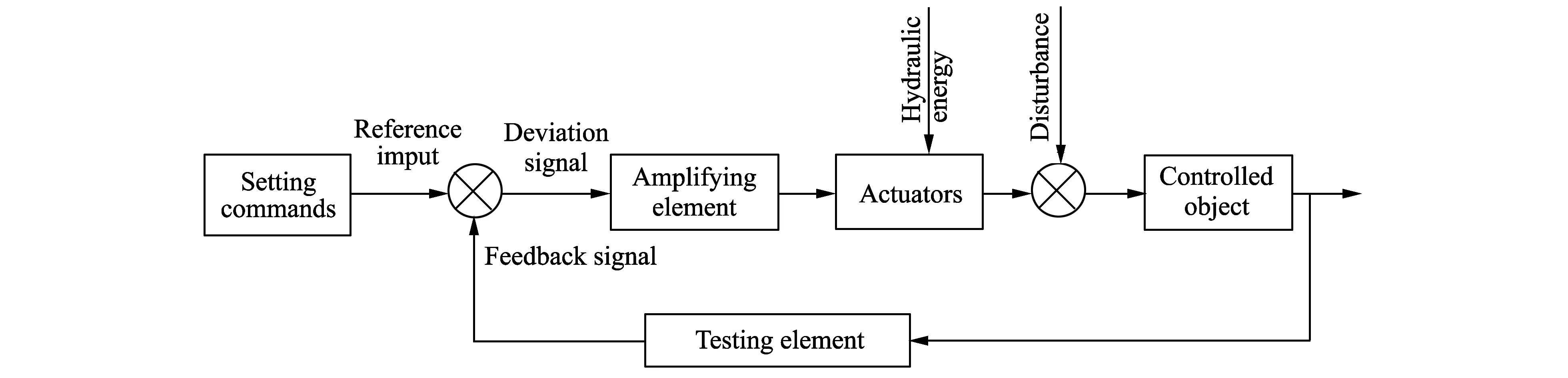
Fig.1 Block diagram of servo-hydraulic system
The current testing system is required to have the abilities to achieve sophisticated automation control, data acquisition, waveform processing, data storage, fault diagnosis, alarm functions and unguarded quality.
Hydraulic testing technology has developed from simple fault overhaul to fault prediction which clears hidden faults when finding fault signs so as to avoid equipment vicious accidents and improve the accuracy of test results[3].
Because servo-hydraulic technology has the advantages of fast response speed, high control precision combined with improved diagnostic capabilities, powerful components control function of host controller, and so on, it can not only meet the requirements for quality and precision of products, but also achieve real-time processing, real-time compensation and real-time monitoring[4].
1 System overview
1.1 System components
Servo pressure pulse testing system consists of three parts: servo-hydraulic system, measurement and control system and mechanical system[5].The difference between the references and this paper is that the references are a single pulse system and our system is a double-pulse system.
Mechanical system is the basis of the testing system.As the installation platform of the testing system which includes toolings, boxes, brackets and other components, all the testing aesthetic and protection functions must be completed based on mechanical system.
Hydraulic system is the core of testing system for it provides the system with necessary power.It can determine whether the performance of the entire hydraulic system is good or not.The commonly-used hydraulic system inclueds pump, valve and other hydraulic auxiliary components.There are pressure systems, cooling systems, heating systems and other systems.
Measurement and control system is the soul of the system, which makes the entire system operate under efficient automatic control[6-7].
1.2 System requirements
It is necessary for the system to test the temperature and pressure pulses of 1-8 radiators, condensers, evaporators and other internal parts simultaneously to assess the fatigue properties.According to the national standards, the test rig can achieve three waveforms: sine wave, trapezoidal wave and triangle wave.The system is divided into two parts: high pressure part and low pressure part.The high pressure part can do high-pressure test for hose, etc., and the low pressure part can do low-pressure test for condenser, etc.The system requires the abilities to run not only independently, but also together.
1.3 Servo-hydraulic system
Fig.2 is the schematic diagram of servo-hydraulic system, which shows the principle of the servo pressure pulse testing equipment.
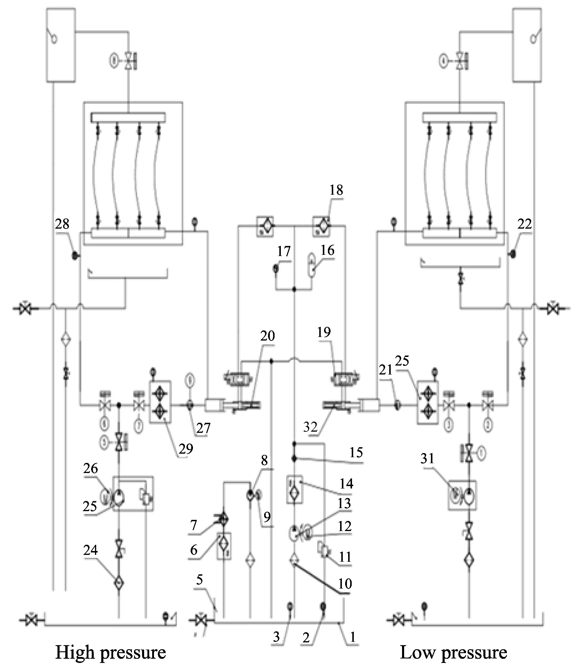
1-Tank; 2-Level gauge; 3-Temperature sensor; 4-Manual ball valve; 5-Float; 6-Filter; 7-Cooler; 8-Vane pump; 9-Cooled motor; 10,24-Oil suction filter; 11-Relief valve; 12-Main motor; 13-Piston pump; 14,18-High pressure filter; 15-Check valve; 16-Accumulator; 17-Gauge; 19-Servo valve; 20,32-Pressurized cylinder; 21,27-Circulation pump; 22,28-Pressure sensor; 23,33-Heater; 25,31-Fluid infusion pump; 26-Fluid infusion motor; 30-Solenoid valveFig.2 Schematic diagram of servo-hydraulic system
2 Measurement and control system
2.1 System components
The measurement and control system for servo pressure pulse testing includes PC, collecting devices, control devices, drive devices and other parts.
The system uses the industrial computer from Advantech Company as PC.It has stable performance and strong anti-jamming capability and is suitable for industrial production.The system uses LabVIEW software for programming.Firstly, advantech data acquisition card collects sensor signals, and then uploads the signals to the upper computer for processing.The system adopts PLC control device to control input and output signals for automatic control.The system also includes inverters, servo valves, solenoid valves, driving components, and accessory equipment such as sensors, electronic instruments, and so on.
The measurement and control system integrates the acquisition, processing, control, driving, monitoring and protection of signals to realize the real automation.
Fig.3 shows the hardware architecture of the measurement and control system.

Fig.3 Block diagram of measurement and control system
LabVIEW is used as the upper computer software and PLC as the lower computer with PLC by VISA[6-7].It can make data and signals communicated and be controlled in real time.
Therefore, the system achieves a closed-loop servo control: given signal→signal driving→signal acquisition→signal feedback→signal processing→signal driving.
2.2 Amplification system
Servo amplifier is a DC power amplifier which drives the servo system.It is an important part of servo-hydraulic control system.It must match with servo valve to improve the steady-state and dynamic performance of the servo system.
The role of amplifier is to compare input command signal with feedback signal, amplify and compute it, and then output a control current, which is proportional to the deviation signal, to the servo valve coil to control the valve opening.
Servo amplifier requires a linear gain, convenient zero, gain adjustment mode, fast response, sufficient output power, overload protection and anti-interference, also it must have good stability and reliability.
2.3 PLC
2.3.1 Introduction to PLC
PLC uses a programmable memory to store its internal procedures, perform user-oriented operating instructions of logical operations and sequential control, timing, counting and arithmetic.Through digital or analog input/output instructions, PLC controls all types of machinery or production processes[8-9].PLC has the following distinctive features:
1) Easy to use, program and debug.
2) Strong functions, high cost-performance ratio and short development cycle.
3) High reliability and strong anti-jamming capability, easy to maintain.
In view of the above advantages, PLC control is selected.
2.3.2 Selection of PLC
The steps of PLC selection:
1) Analyze the system and propose the control requirements.
2) Determine input and output devices, and then determine I/O points.
3) Select PLC models.
According to the system requirements and program design, there are 22 digital input points and 20 digital outputs, 6 analog inputs and 2 analog outputs.The system uses CP1E-N40SDT-D of Omron as CPU, CP1W-8ET as digital expansion modules and CP1W-TS102 as temperature expansion module.In view of sampling frequency, advantech acquisition card PCI-1716 instead of the expansion module is used as analog capture device.
2.3.3 Data processing
Because PLC is based on digital signals, the conversion between analog and digital signals is necessary.While reading analog signals, firstly PLC converts voltage or current signals into digital signals, and secondly reads the digital signals into PLC.At the same time PLC converts digital signals to voltage or current signals while it needs to write analog signals.The resolution of Omron PLC is 6 000[10].
2.4 Application of LabVIEW in the system
LabVIEW is data-acquisition software of NI, USA.It can conveniently complete data acquisition and signal processing.Furthermore, it has a strong external interface capability.Therefore, it saves development time and greatly improves programming efficiency.
Combination of LabVIEW and PLC is the development trend for automatic control.Communication interface is a bridge between PLC and PC.The system integrates PLC and computer to achieve automatic control through the interface[11].
VISA can realize the commuoication between PLC and LabVIEW[12].Fig.4 is a communication program for digital signals by VISA.
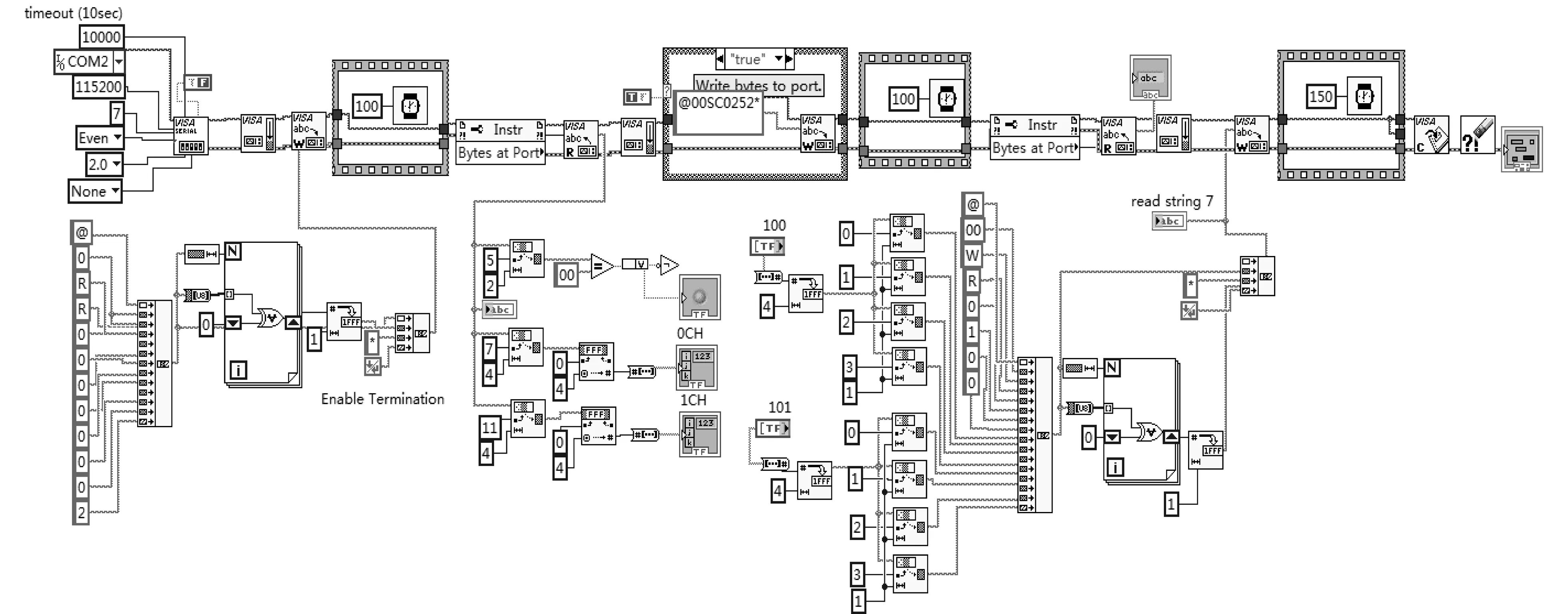
Fig.4 VISA program
The software structure of the system includes data collection and communication module, data reading and writing module, waveform generating and data processing module, data reporting module, automatic control module and alarming module, as shown in Fig.5.
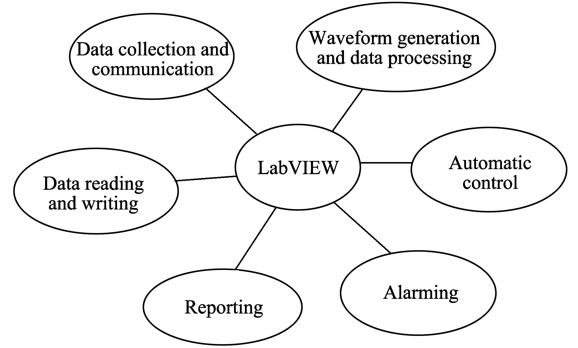
Fig.5 Software structure
Fig.6 shows the software interface.The left part is the waveform for high-pressure system, and the right part is for low-pressure system.The high-pressure system and low-pressure system are working simultaneously for sine wave at this time in Fig.6.
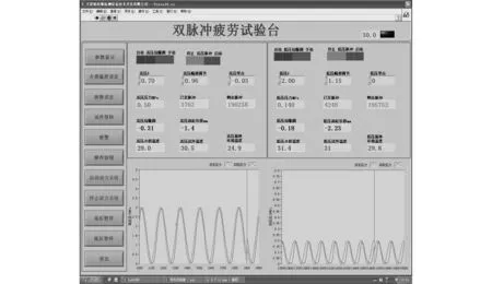
Fig.6 Software interface
Figs.7 and 8 are the waveform acquisition interfaces.Fig.7 is triangular wave for high-pressure system.Curve 1 represents the set curve and curve 2 represents the actual curve.The actual curve fluctuates within the allowable range.
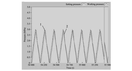
Fig.7 Triangular wave
Fig.8 is water hammer wave.Curve 1 represents the upper pressure limit, curve 3 represents the lower pressure limit and curve 2 represents the actual waveform.The waveforms are strictly controlled within the allowable ranges.So they meet the requirements.
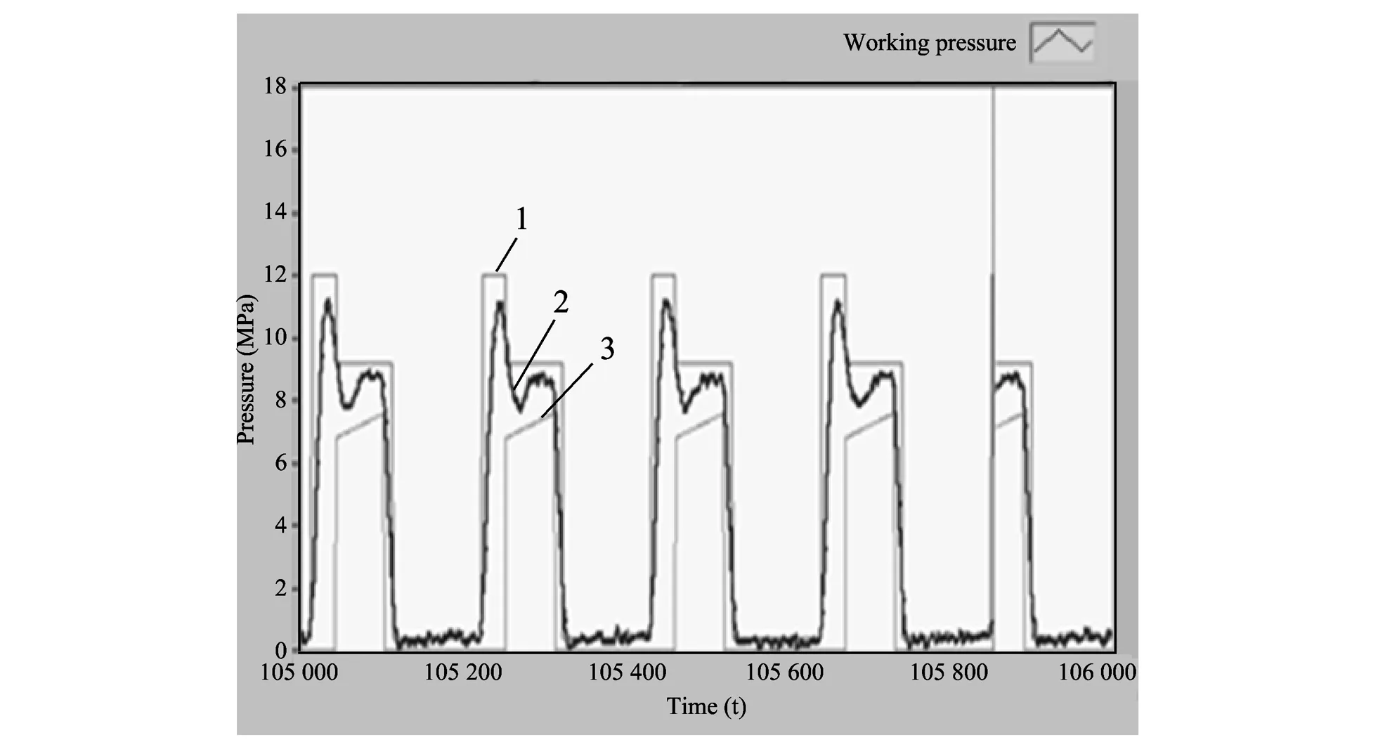
Fig.8 Water hammer wave
2.5 Affecting factors
There are many factors affecting the testing results, such as media properties, temperature, performance of the hydraulic system and PID parameters of the servo system.
1) Influences of medie properties on testing system means that the density and kinematic viscosity of the medie will change as the temperature changes, and the volume of the compression factor and elastic modulus will vary with air mixing.
The most suitable medium must be found and the most suitable operational parameters must be chosen to improve the system, not to completely resolve the problem.
2) The hydraulic system affecting the waveform mainly refers to the selection of hydraulic components.The performance of hydraulic components directly affect the waveform of the system.During the testing, it can be found that the system with minimum pressure was maintained at about 2 MPa because the pressure in the circulation pump itself was about 2 MPa.As a result, it is replaced by shielding pump to aviod the low pressure from being too high.
3) PID parameters of servo valve determine the quality of the servo system.Choosing the most reasonable parameters is the most important task.It is useful to combine the experience with theoretical calculation.The theoretical calculation is used for PID parameters, but the data obtained by theoretical calculation are not necessarily accurate, so it is also needed to adjust the settings for several times until the optimal parameters are found to make the waveform within the range of the standard waveform.
3 Conclusion
The servo pressure pulse testing system can achieve the automotic condensers, radiators and automobile lines for pulse pressure test, including high-pressure system and low pressure system.They can test not only independently, but also separately.The two systems share the same hydraulic station (that is power system).
PC uses LabVIEW to collect and process the signals as well as store and display the pressure waveform.It also can record in real time[13].
The system adopts PLC to control the system to complete the entire exercise in accordance with the requirements.And it has the perfect alarm processing function, which can be achieved unattendedly, safely and reliably.Alarm data can be recorded.The system can analyze the cause of the alarm and find reasonable solution to process the alarm.It also has communication, printing and other functions.Test parameters can be set simply and quickly, and can be set according to the requirements of users.
[1] WU Jun-hui, LIU Xi-ding, SONG Lian-wang.Research for measurement and control system of hydraulic servo pressure pulse based on LabVIEW.Science and Technology Communication, 2012, 5(11): 90-93.
[2] ZHU Yu, ZHAO Ti-bo.Data acquisition and processing of pulse hydraulic fatigue testing machine.Machine Tool & Hydraulics, 2009, 37(11): 129-131.
[3] Ruiz M, Barrear E, Lopez S, et al.Real-time data acquisition and processing platform for fusion experiments.Fusion Engineering and Design, 2004, 20(5): 81-85.
[4] ZHAO Meng-wen, YUAN Zhao-hui, WANG Hong-hui.Design for high pressure pulse test rig.Hydraulic and Pneumatic, 2009, 6(11): 23-25.
[5] CHEN Dong-ning.Design for pulse testing machine based on the hydraulic-servo and virtualization technologies.Hydraulic and Pneumatic, 2013, 10(3): 76-78.
[6] CAO Ling-zhi.Modern testing technology and virtual instrument.Beijing: Beijing University of Aeronautics and Astronautics Press, 2004: 56-70.
[7] MA Zhen-feng, LIU Xian-li, WANG Peng.Communication between PC and PLC based on LabVIEW 7.1.Journal of Harbin University of Science and Technology, 2005, 10(5): 30-34.
[8] LI Hong-liang.Implementation of real-time communication between PC and PLC base on OPC.Application Research of Computer, 2003, 10(5): 115-117.
[9] Omron CPM1H PLC programming manual.OMP-ZCO97101B, 1997.
[10] Czop P, Sawik D.A high-frequency first-principle model of a shock absorber and servo-hydraulic tester.Mechanical Systems and Signal Processing, 2011, 25(6): 1937-1955.
[11] Gillich G R, Frunzaverde D, Gillich N, et al.The use of virtual instruments in engineering education.Procedia-Social and Behavioral Sciences, 2010, 2(2): 3806-3810.
[12] GUO Bei-tao, LIU Hong-yi, CAO Yang.Measurement and control system of solenoid valves integrated nature based on virtual instrumentation.Journal of Scientific Instrument, 2010, 31(2): 293-298.
[13] Odon A, Krawiecki Z.LabVIEW application for computer simulation of the conversion technique of dual-slope analog-to-digital converter.Measurement, 2011, 44(8): 1406-1411.
伺服壓力脈沖檢測設備的測控系統研究
宮玉潔, 劉新福, 劉力平
(河北工業大學 機械工程學院, 天津 300130)
摘 要:電液伺服壓力脈沖檢測設備采用伺服液壓技術構建系統模型, 通過完善測控系統, 實現了數據信號的采集處理和過程控制。 基于LabVIEW與PLC進行硬件配置和軟件開發, 調用VISA函數實現兩者間通訊, 使系統能夠按照預設指令進行自動化控制, 提高了檢測系統的精度和性能。
關鍵詞:PLC; LabVIEW; 液壓伺服系統; VISA
引用格式:GONG Yu-jie, LIU Xin-fu, LIU Li-ping.Measurement and control system for servo pressure pulse testing equipment.Journal of Measurement Science and Instrumentation, 2014, 5(4): 83-88.[doi: 10.3969/j.issn.1674-8042.2014.04.016]
Article ID:1674-8042(2014)04-0083-06
10.3969/j.issn.1674-8042.2014.04.016
Receiveddate: 2014-06-11
Foundation item:High Level Talented Person Funded Project of Hebei Province (No.C2013005003); Excellent Experts for Going Abroad Training Program of Hebei Province (No.10215601D)
Corresponding author:LIU Xin-fu(liuxf999@163.com)
登錄APP查看全文
 Journal of Measurement Science and Instrumentation
2014年4期
Journal of Measurement Science and Instrumentation
2014年4期
- Journal of Measurement Science and Instrumentation的其它文章
- Nonlinear principal resonance of magneto-electro-elastic thin plate
- Effect of TPB on curing reaction of HTPB-TDI
- Polarization state measurement based on photoelastic modulation
- Mosaic line-scan camera based on FPGA
- Detection technique of moving target based on passive millimeter wave
- Empirical model of correction for zenith tropospheric delay