關門巖電站受油器故障分析及處理
2015-07-28 02:38:44李志堅湖南澧水公司江埡水電站湖南慈利427221
水電站機電技術 2015年1期
李志堅(湖南澧水公司江埡水電站,湖南 慈利 427221)
關門巖電站受油器故障分析及處理
李志堅
(湖南澧水公司江埡水電站,湖南 慈利 427221)
摘要:受油器在燈泡貫流式機組中是一個非常重要的部件,直接影響著機組的大修周期及整個值班模式,本文具體分析了受油器常見故障的原因,重點分析了受油器中管擺度大的原因,并提出了很好的解決處理方案。
關鍵詞:受油器;同心限位環;大軸內徑最小點
受油器是燈泡貫流式機組的一個重要的部件,將靜止的壓力油傳輸到旋轉的轉輪輪轂內以推動槳葉開關,高壓油在動靜傳遞過程中的密封要求高,旋轉密封是世界難題,何況水輪發電機組的旋轉線速度大、振動擺度大且操作油壓高。
1 受油器故障特征
關門巖電站位于湖南省慈利縣,澧水一級支流婁水中下游,電站安裝3臺單機容量為11MW的燈泡貫流式機組,為已建成的江埡水利樞紐的反調節電站。三臺機組于2007年全部投產發電,一直以來調速器壓力油泵啟動頻繁,受油器漏油嚴重,浮動瓦容易磨損,每年必須更換浮動瓦,檢查發現浮動瓦軸向方向出現許多深度約為0.1mm左右的環形溝槽和拉傷痕跡,浮動瓦的徑向邊也存在明顯的摩擦痕跡,浮動瓦軸向和徑向方向都存在偏磨的現象。
2 受油器結構
關門巖電站的受油器是一種比較典型的結構設計,由三塊浮A、B、C動瓦形成兩個密封壓力油腔,操作油外管安裝在轉子中心體法蘭上,中管套裝在機組大軸和外管內腔,中管外壁上均布有8條60mm×12mm的滑塊定位,保證中管和外管的同心度,導向頭以螺紋(M130×4)的方式左旋入中管的端部(見下頁圖1)。
3 運行中存在的問題及分析
(1)調速器壓力油泵啟動頻繁,浮動瓦運行時間2500h左右必須更換,每次檢修發現浮動瓦磨損嚴重,浮動瓦與導向頭及外管接觸面上有許多深淺不一的劃痕,且明顯存在偏磨的現象,而且與導向頭配合的B、C兩塊浮動瓦側面磨損很嚴重,這說明浮動瓦在運行過程中徑向擺度很大,中管與外管間隙較大,設計間隙為0.5mm左右,實際測量中管與外管間隙竟達到5mm左右,也許大家會認為這是安裝的原因,其實有更深層次的原因,后面處理方案中有詳細分析。
(2)與外管配合的A瓦也有許多劃痕,實測外管擺度為0.08mm左右,擺度較好。這說明油質較差,管路安裝過程中清理不干凈。
(3)導向頭端蓋嚴重偏磨,每年必須換向或更換,這主要是導向頭擺度過大引起,同時受油器外管與受油器本體不同心也有一定關系。
(4)槳葉接力器抽動,槳葉主配壓閥配油頻繁,這一般出現在浮動瓦運行時間快一年的時候。這說明主要也是浮動瓦漏油引起,同時槳葉接力器密封不好也會產生同樣的后果。
4 處理措施
對受油器存在的問題進行分析,浮動瓦的磨損而引起密封不嚴漏油是故障的主要象征,其主要原因就是中管擺度過大,而油質不好、槳葉接力器密封不好、受油器同心度偏差等是次要原因。
4.1中管擺度過大處理
浮動瓦擺度過大主要是因為中管與外管間隙過大,我站實測單邊間隙達到5mm左右,中管上有8條定位滑塊以保證中管與外管的同心度,設計間隙為0.5mm,是否可以將外管上的定位滑塊加大再與外管精細配合即可,實際操作根本不可行。機組大軸內孔內徑呈現兩頭大中間小,呈喇叭口(如圖2),D1=D3>D2,這主要是由于機組大軸內孔在加工過程中由于車床懸臂饒度引起內孔尺寸的不一致。
中管安裝是由尾水管轉輪處往大軸內插入,所以定位滑塊外徑最大不能超過D2,否則中管無法插入,這樣中管與外管的單邊最小間隙為(D3-D2)/2=4mm,無法達到廠家0.5mm的要求,所以單純只增大定位滑塊的尺寸是無法徹底解決中管與外管間隙過大的問題,這也是國內同類機組無法根除此問題的重要原因之一。
僅通過加大限位滑塊的尺寸無法解決此問題,于是在外管圓周方向鉆三個沉頭定位螺栓來固定中管,第一臺機組A級檢修中按此方案實施,但實際效果不是令人很滿意。此方案主要存在如下缺陷:1)在外管上鉆孔攻絲,影響外管強度,定位螺栓調整完畢后必須用蓋板焊接,容易產生焊接變形;2)不便于具體實施操作。首先中管與外管的同心定位沒有合適的基準,同時每次調整定位螺栓會引起外管的盤車數據也發生改變,盤車時間長,盤車數據基準易變。開機運行后,出現過定位螺栓漏油的現象,外管擺度達到0.2mm左右(機組在線監測數據),并有增大的趨勢,效果不能令人滿意。
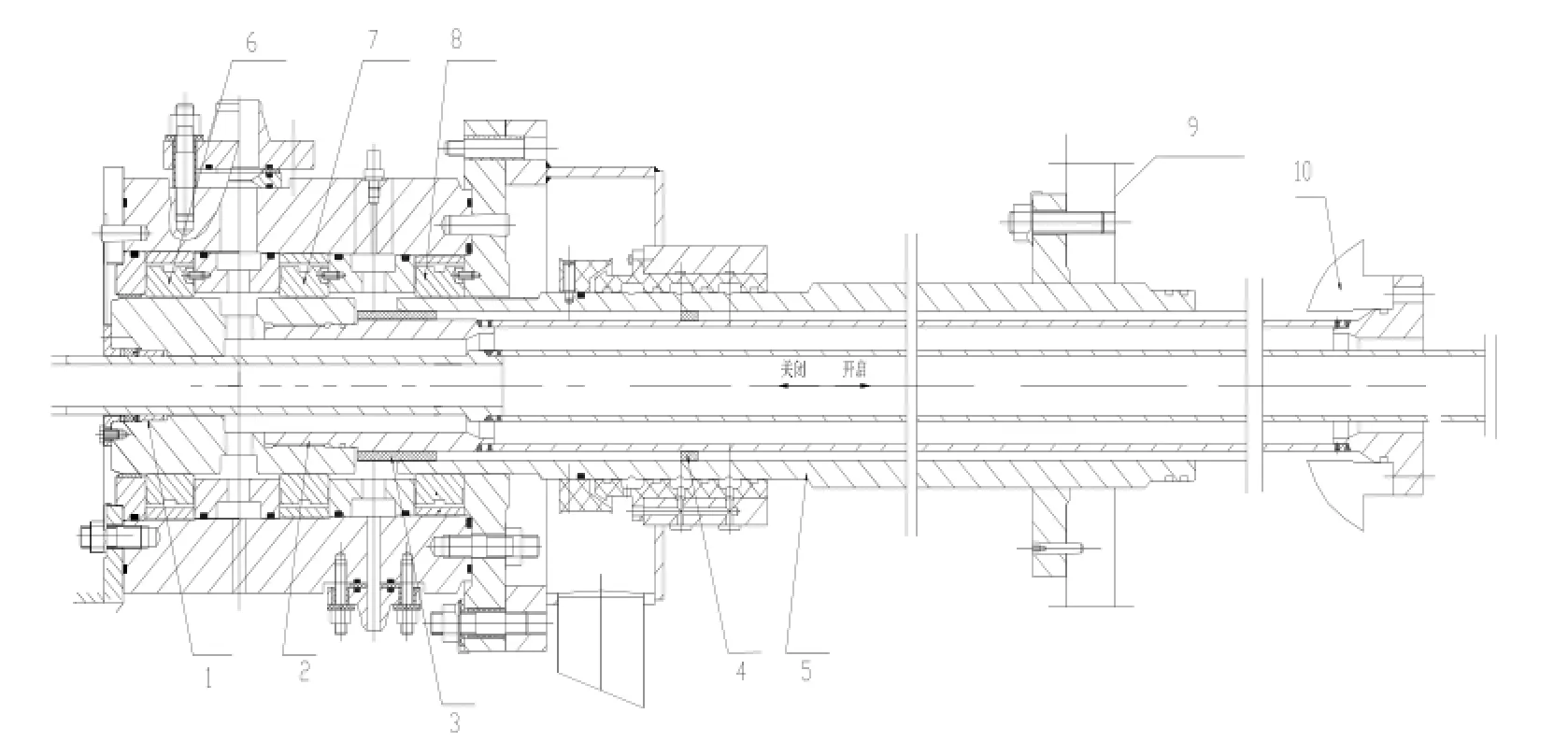
圖1受油器結構圖
1、導向頭;2、中管;3、同心限位套(改造制作);4、定位滑塊;5、外管;6、浮動瓦A;7、浮動瓦B;8、浮動瓦C;9、轉子支架;10、槳葉接力器活塞
通過第一臺機組受油器檢修處理,對整個處理方案有了更深刻的認識,吸取了前次檢修的經驗,終于完美的解決了中管擺度過大的問題,主要過程如下:
(1)制作大軸內孔測量專用工具,測出最小內徑D2和最小點B點到槳葉接力器活塞端面的長度L的具體數值。將一個直徑為130mm的法蘭盤,在圓盤四周鉆孔攻絲安裝四個均布的調節螺栓,螺栓頭部焊接圓珠,法蘭盤固定在鍍鋅鋼管上,將法蘭盤插入機組大軸內,通過調整法蘭盤上的調節螺栓,最終可測出大軸內徑最小值D2為152mm,L值為3.79m,而D1為160mm,然后在中管的對應位置焊接定位滑塊精確配合,確保中管與大軸內孔間隙幾乎為零。
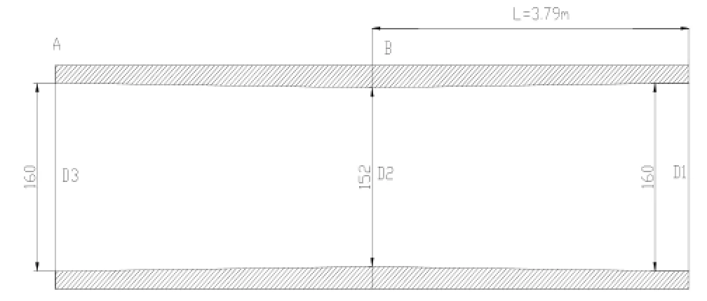
圖2中筐
(2)制作外管與中管之間的同心限位環。前面提到,中管前端與外管有很大間隙,最小也有(D3-D2)/2=4mm,而第一次檢修中用定位螺栓的方案效果不很理想,于是想到在中管與外管之間嵌入一個同心限位環。首先將中管外徑上車削一個臺階,直徑為130mm,公差為(-0.05,0),長度為8mm,用內徑量表測得外管內徑為160mm,公差(0.03,0.05),于是加工限位環(如圖3),保證限位環內徑公差與中管相配,外徑公差與外管相配,最終限位環具體尺寸如下:內徑為130mm,外徑為160mm,長度為80mm,同時在定位環上刨出四個槽讓油流通過,注意過流面積必須保證輪葉開關機時間。
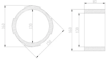
圖3限位環
這樣中管通過端部法蘭螺栓、大軸最小點B點處定位滑塊,以及同心限位環三點完全固定死,中管與外管及大軸間的間隙幾乎為零。
4.2其他次要原因的處理
(1)確保透平油過濾干凈,管路安裝前全部用白棉布進行抽拉,清潔管路不留死角,做到一絲不茍。
(2)外管與浮動瓦接觸的部位進行鍍鉻處理,先將外管磨小0.1mm左右,再熱鍍同樣厚度的鉻層,大大提高外管的光潔度及硬度,減少對浮動瓦A瓦的磨損。
(3)將轉輪體芯與槳葉接力器油缸密封更換為兩道車氏密封,第一道密封為聚四氟乙烯滑環加O型圈組合,第二道密封為聚氨酯加O型圈組合,這種密封設計壓力可達到60MPa,安裝完畢后我們現場打壓6.3MPa,保壓2h,幾乎沒有滲漏,效果很好。
(4)嚴格盤車數據,外管盤車時應注意連接螺栓的憋勁,確保外管擺度不大于0.1mm,我站外管盤車擺度最終為0.08mm。
(5)保證受油器本體與外管同心。用內徑量表測量受油器本體與外管的內徑大小,調節受油器本體與外管同心度,偏差不大于0.1mm,同時將受油器連接管路全部更換成軟管。
5 結論
受油器回裝完成后,機組投入正常運行,外管擺度為0.05~0.06mm(機組在線監測數據),調速器壓力油泵啟停時間達到了1.5h,機組已正常運行一年時間油泵啟停時間幾乎沒變化,整個受油器改造效果非常完美。
Abstract: Guide vane apparatus is one of key parts for a set of hydropower unit. In China, the installation of guide vane apparatus for Francis turbine should be carried out after pre-assembly normally. Taking other hydropower stations into consideration, the none field pre-assembly of guide vane apparatus is discussed and provided to peers.
Key words: guide vane apparatus; hydroturbine; pre-assembly; field
中圖分類號:TV738
文獻標識碼:B
文章編號:1672-5387(2015)01-0060-03
DOI:10.13599/j.cnki.11-5130.2015.01.020
收稿日期:2014-08-28
作者簡介:李志堅(1973-),男,工程師,從事電廠運行及檢修管理工作。
Vibration characteristic analysis of mixed flow hydroturbine runner based on fluid structure interaction
ZHANG Xin1, ZHENG Yuan1,2, ZHANG De-hao3, WANG Zhong-feng3, WEI Qing-lian3
(1. College of Energy and Electrical Engineering, Hohai University, Nanjing 211100, China; 2.National Engineering Research Center of Water Resources Efficient Utilization and Engineering Safety, Hohai University, Nanjing 21098, China; 3. Baishan Power Factory, Xinyuan(Holdings) Company Limited, State Grid, Jilin 132400,China)
Abstract:The resonance of turbine will cause resonance crack on the turbine blade,so it is necessary to calculate the natural frequency of turbine to avoid external excitation frequency. The fluid structure interaction (FSI) method which combines CFD software CFX and finite element software ANSYS Workbench is introduced in the present paper. The finite element modal analysis is made on a domestic Francis turbine to calculate the modal of the turbine with and without considering the pre-stress respectively. Natural frequencies and mode shapes of the turbine are calculated in the air and water respectively. The results show that the natural frequencies of the turbine will increase by considering the pre-stress. However,the increasing ratio is less than 0.5%, so the effects of pre-stress can be ignored. Natural frequencies in water are reduced significantly than that in air, and the declined degrees vary in different frequency order. The general trend of drop coefficient is reduced with the increase of frequency order.
Key words:Turbine; modal analysis; FSI; pre-stress
Research and application of self-adjusting forced thrust bearing supported by elastic cushion
WANG Huan-dong
(Zhejiang FF Electrical Power Equipment CO., Ltd, Hangzhou 311201, China)
Abstract: The synthetic rubber elastic cushion which is installed under the thrust pad will generate self-adjusting for the forced thrust bearing. It has simple structure, excellent self-adjusting performance, low temperature difference in bearing shell and stable operation. The self-adjusting function of axis for thrust bearing makes the jigger without scraping and the axial line without dealing. It is the best choice for the medium and small type of generator unit to change the rigidity thrust bearing into elastic cushion thrust bearing.
Key words: rigidity thrust bearing; synthetic rubber elastic cushion; elastic cushion thrust bearing
Discussion of DC system operation for large station based on a DC grounding fault
XU Peng
(Longtan Hydropower Development Co., Ltd., Tian’e 547300, China)
Abstract: Based on the analysis of an instantaneous direct current (DC) system ground fault, it is found that the parasitic circuit brings about the ground fault in two completely independent DC system simultaneously. The wide use of devices such as microprocessor-based insulation monitoring device, static type protection device, filtering circuit, long cables and so on in large plant station makes DC system operation have some new problems. The operation of large-scale plant station with DC system under the new situation is discussed.
Key words: DC system; ground fault; insulation monitoring device; equivalent capacitance
Feasibility study of field pre-assembly and none pre-assembly for guide vane apparatus
TANG Zhi-an, LI Zhi-hui
(
Toshiba Hydro Power (Hangzhou) Co., Ltd, Hangzhou 311504, China)