A process design for large diameter of flanging hole and the calculation of the flanging force
2015-11-03 07:02:03LeiWUBinLIULigangDING
機床與液壓 2015年3期
Lei WU, Bin LIU, Li-gang DING
(1Equipment Manufacturing Department, Zhongshan Torch Polytechnic, Zhongshan 528437, China)(2School of Mechanical & Automotive Engineering, South China University of Technology, Guangzhou 510641, China)
?
A process design for large diameter of flanging hole and the calculation of the flanging force
Lei WU1, Bin LIU2, Li-gang DING1
(1Equipment Manufacturing Department, Zhongshan Torch Polytechnic, Zhongshan 528437, China)(2School of Mechanical & Automotive Engineering, South China University of Technology, Guangzhou 510641, China)
It cannot be processed in the existing hole-flanging process when the flanging hole and tube have the same diameter. Therefore, a new process is proposed. Taking the deformation characteristics of new process, the work-hardening ability and the thickness change in the deformation zone into consideration, this paper presents a calculative method for tube flanging force. The simulation data in Abaqus show that the flanging force in this paper is more accurate than the sheet flanging force formula.
Flange, Flanging force, Work-hardening, FEM simulation
1 Introduction
Collection tube is an important component for air conditioning and refrigeration equipment. The quality of tee flanging process affects the merits of the collection tube products. Currently, the hole-flanging process is mainly based on the principle of stamping which is powered by pneumatic or hydraulic systems. Punch stamps the tube out directly from the inside of the tube under the combined action of metal tube punching device and flanging die [1-2]. This process requires simple equipment. However, because the metal punching device is placed in a metal tube, flanging hole is much smaller than the diameter of the metal tube, and it cannot be processed in this hole-flanging process when the flanging hole and tube have the same diameter as shown in Fig. 1. Therefore, a new process is proposed to process flanging hole which has the same diameter with the metal tube.
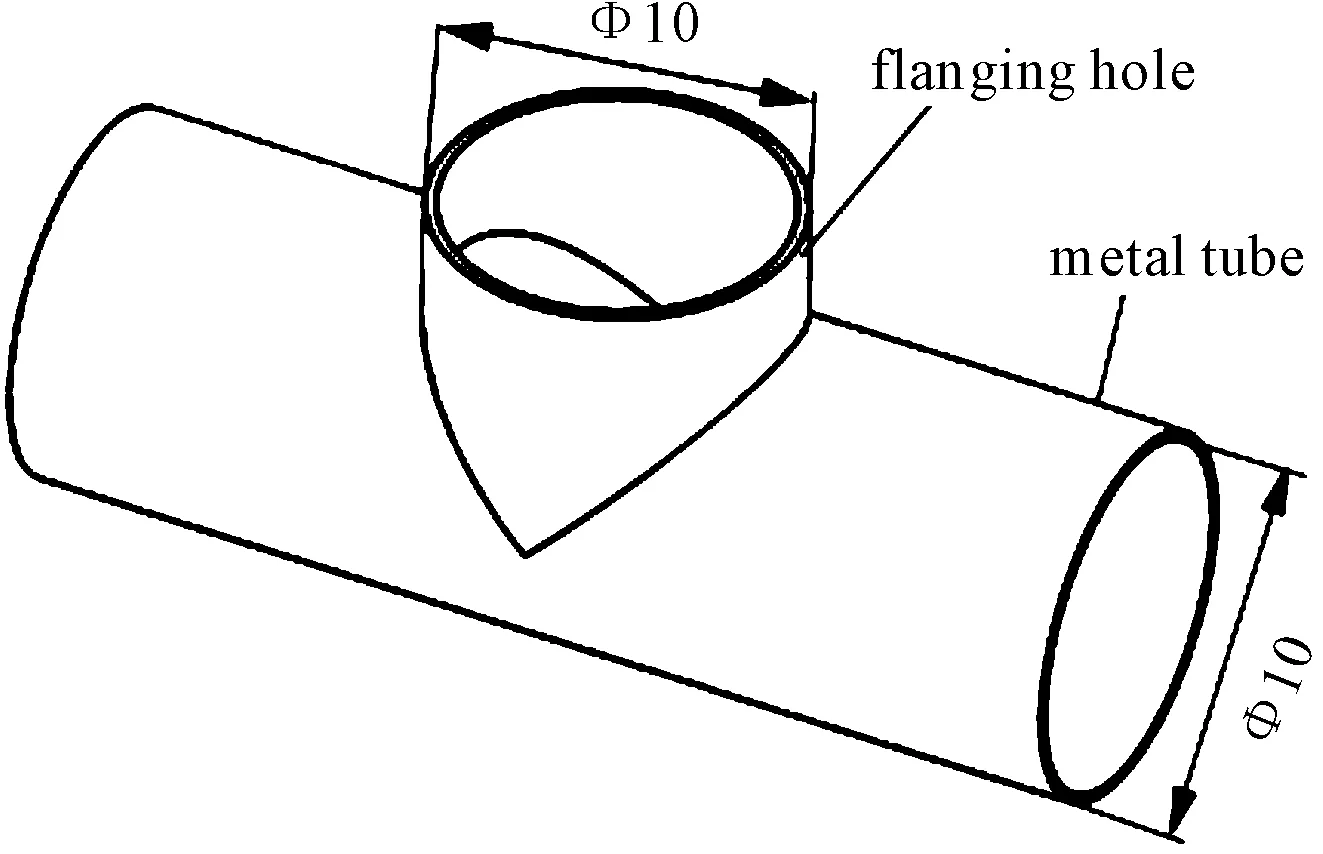
Fig.1 Size requirements of hole-flanging process
2 Process design
2.1 Equipment
The equipment of hole-flanging is shown in Fig.2. To achieve the hole- punching and external hole-flanging of the metal tube, the equipment consists of punch, die, gas supply and other components. The fins on the both sides of the punch are connected with the spring. Therefore, the fins expand in a natural state and shrink into the punch under the pressure in the radial direction.
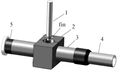
1.punch; 2.die; 3.metal tube; 4.gas supply equipment; 5.head
Fig.2 The equipment of hole-flanging
2.2 Flanging process
The process is shown in Fig.3. Metal tube is placed in the die, and then the die merges. Then one side of the tube connects to the gas supply equipment and the other connects to the head. High pressure gas supplied by gas supply equipment is passed into the tube. Then the punch punches hole is shown in Fig.3(a). Because the high pressure gas acts as the die, deformation of the metal tube is small. After the formation of punching, the gas supply is stopped and the fins shrink into the punch under the pressure of the tube in the radial direction, as shown in Fig.3(b). When the fins are entering into the tube completely, the fins expand under the action of the spring, and the pre-punched hole has formed, as shown in Fig.3(c). Then, the punch with high-speed rotation moves up slowly. A hole-flanging is formed under the combined action of the punch and die, as shown in Fig.3(d).
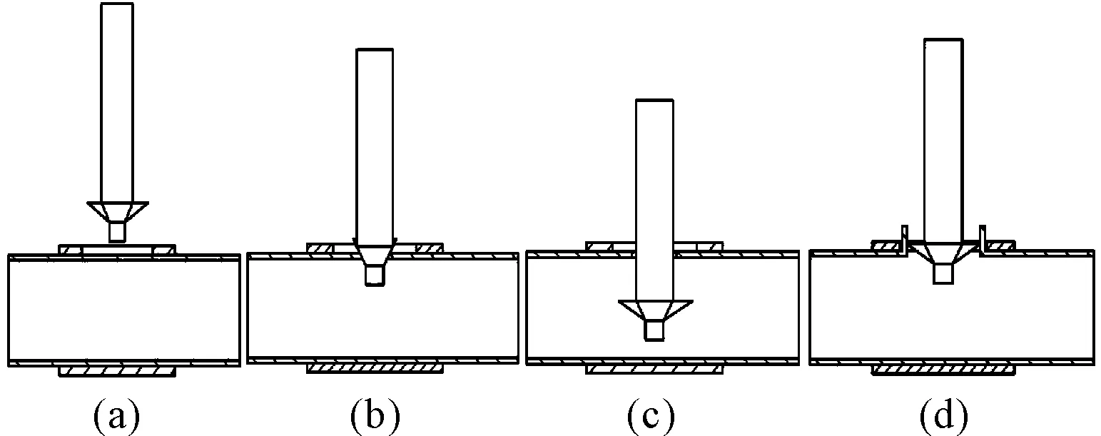
Fig.3 The process of hole-flanging
3 Calculation of flanging force
To calculate the flanging force, the model for flanging is simplified appropriately. Because the punch is high-speed rotation in the flanging process, the punch is simplified as a circular truncated cone. The model diagram is shown in Fig.4.
Flanging force formulas have been proposed by literature [3-4]. But work hardening influences in the flanging have not been taken into account. Later, the work hardening effects have been taken into consideration in the literature [5-7] where the work hardening law has been represented by a slope-intercept form or a power function. However, the flanging force in the above literature is calculated for sheet instead of the tube. Until now, few calculations of the flanging force for tube are found.
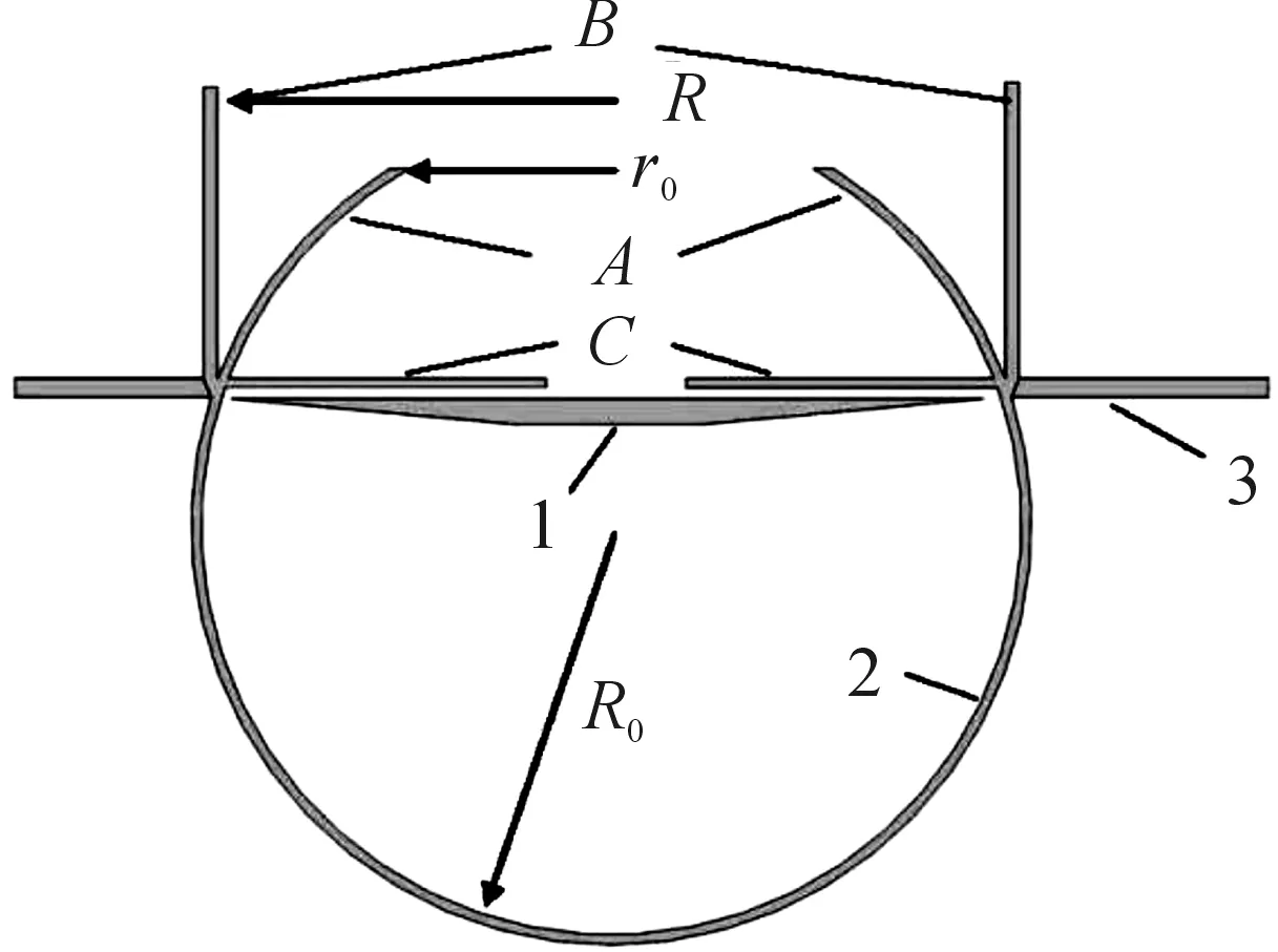
1.punch; 2.metal tube; 3.die
Fig.4 Zone position state deformation of hole-flanging
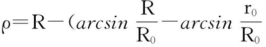
According to the derivation of the flanging force for sheet, the hole-flanging for sheet in analogy with the hole-flanging for tube is proposed. To simplify the calculations, only radial section deformation of the tube is considered. The hole-flanging deforms from position A to position B. Position C, which is the initial state of the sheet flanging, is equivalent to the position A.
The wall thickness of the tube is ignored. Tube radius is R0. While the pre-punched hole radius is r0and flanging hole radius is R. The distance between a point in position A and the center is supposed to be r, and the distance between the certain point in position C and the center can be expressed as
(1)
The punch shoulder is ignored, and the distance between the certain point in deformation region and the center can be expressed as
(2)
whereαis the wrap angle between deformation region of tube and die, and the fillet radius of die is rd. Work hardening law is expressed as a power function, namely that the stress-strain curve of tube can be expressed as
(3)
where K is a material constant, MPa, n is the material strain hardening exponent, andεis the logarithmic strain of a point in the deformation region, that is
It is assumed that the tangential stress of a point in deformation region is σθ, and the radial stress is σp. Compared with the other two principal stress, the stress in the thickness direction is much smaller, therefore, the stress in the thickness direction σt≈ 0. The equilibrium equation of stress can be expressed as
(4)
The yield criterion is
That is
(5)
Combining Eqs. (2) ~ (5), the equilibrium equation of stress can be expressed as
(6)
Because the flanging coefficient is usually greater than 0.5, that is the right part of Eq. (6) can be simplified by

(7)

(8)
where rtis the radius of the hole in deformation region of a deformation moment. That is
(9)
When the material is exposed to the sharp part of the punch, friction between the tube and the punch should be taken into consideration for the radial stress. It can be simplified by the formula given by literature [8]
(10)
where μ is the coefficient of friction between the material and the punch.
What’s more, there will be an increment of deformation stress when the material is exposed to the sharp part of the punch [9], namely that the radial stress σpcan be expressed as
(11)

Accordingtoaboveliteratures,whenthedeformationregionislocatedinthegapbetweenthepunchandthedie,thematerialdeformationisthemaximum.Whenthewrapanglebetweendeformationregionoftubeanddiesatisfiesα =π/2andr=R,thatisρ=R,themaximumradialstresscanbegotten
(12)
where
The formula for flanging force is
(13)
where m′ is the deformation coefficient. Because the thickness of material thins when it deforms, m′ = 0.9-0.99. Combining Eqs. (12) and (13), the formula for flanging force can be gotten.
4 Simulation and experiment of flanging force
4.1 Validation
The finite element method (FEM) with DEFORM [10-12] or ABAQUS [13-16] have been utilized to simulate the flanging process. And all of the finite element results were validated by experimental results. Because of the simulation of nonlinear dynamics in ABAQUS, flanging force numerical calculation is conducted by the software. In this simulation, the material of the tube is brass and the Young’s modulus is 115 GPa. The Poisson’s ratio is 0.34 and the yield strength is 240 MPa. And the experiment is conducted by simple flanging dies and universal tensile machine, as shown in Fig. 5.
Flanging force for different diameters, different wall thicknesses and different pre-punched holes are shown in Table 1. The flange force formula for sheet flanging was given by literature [6]. Data for the column of literature [6] is the flanging force corresponding to the same material, the same sheet thickness and the same pre-punched hole. m′ = 0.95, n = 0.328, K=452 MPa, and μ= 0.2.
According to the data of Table 1, if the parameters of tube flanging are substituted into the formula in literature [6] directly, there will be a deviation about 15% from the simulation and experiment data. However, the formula in this paper, its deviation from the simulation data, is about 7%. Thus the formula in this paper is more suitable for engineering applications.
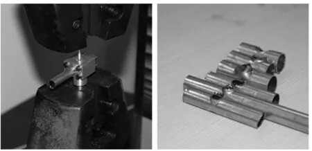
Fig.5 Experiment material and equipment
Table 1 Comparison of maximum flanging force
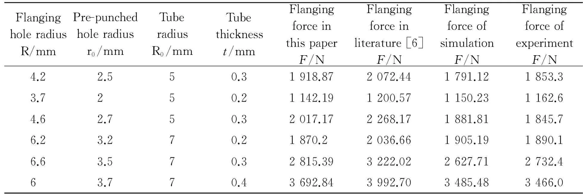
FlangingholeradiusR/mmPre-punchedholeradiusr0/mmTuberadiusR0/mmTubethicknesst/mmFlangingforceinthispaperF/NFlangingforceinliterature[6]F/NFlangingforceofsimulationF/NFlangingforceofexperimentF/N4.22.550.31918.872072.441791.121853.33.7250.21142.191200.571150.231162.64.62.750.32017.172268.171881.811845.76.23.270.21870.22036.661905.191890.16.63.570.32815.393222.022627.712732.463.770.43692.843992.703485.483466.0
4.2 Simulation and calculation
According to the size requirements of hole-flanging process in Fig. 1, simulation analysis is conducted in Abaqus, and the wall thickness of tube is 0.3 mm. The pre-punched hole radius is 3 mm. Simulation results that flanging force changes with the time of punch moving up are shown in Fig. 6, and the maximum flanging force is 1 724.05 N. While the maximum flanging force in Eq. (13) is 1 802.56 N. Both are almost identical, and the maximum flanging force should be 1 800 N.
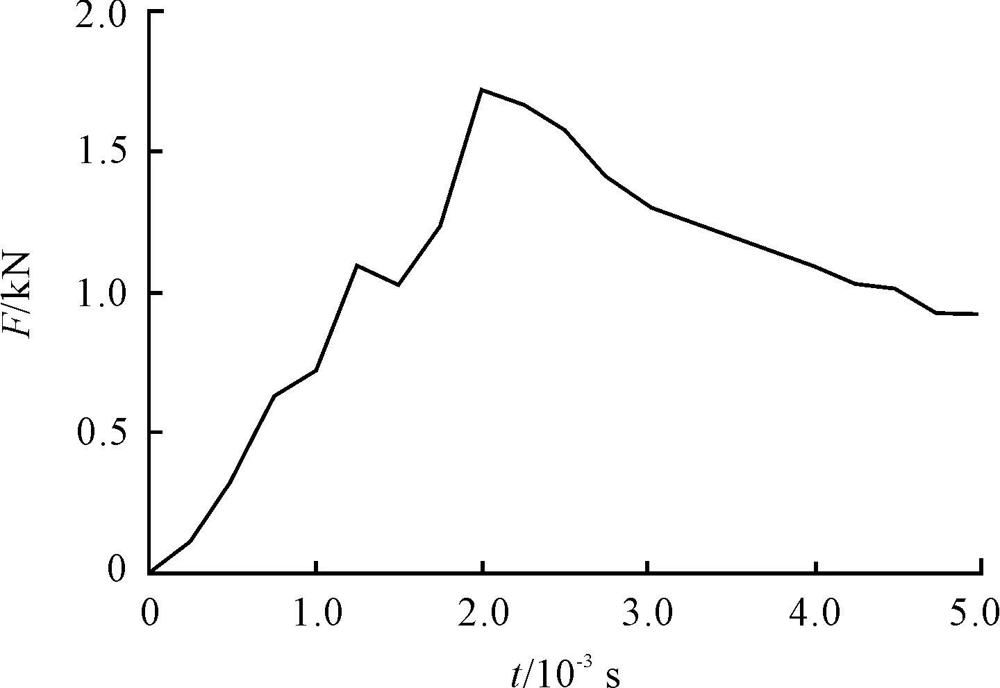
Fig.6 Simulation results that flanging force changes with the time of punch moving up
5 Conclusions
1) A new flanging process is proposed to overcome the deficiencies of the existing tube flanging process. It can process flanging hole which has the same diameter with the metal tube.
2) According to the tube flanging process, and taking the difference between sheet flanging and tube flanging into consideration, flanging force for tube flanging is derived.
3) According to the simulation in Abaqus and the test, the formula in this paper is more suitable for tube flanging.
[1]WANG Xin-zhong, LI Guo-dong, ZHANG Ju-yong. A special-equipment for processing large-diameter hanging-hole on sheet metal [J]. Mechanical & Electrical Engineering Magazine, 2008, 25(5): 109-110.
[2]FENG Li, SUN Shi-xin. Application of Flanging Hole Processing Technology in Cooling System for Copper Pipe Process [J]. Mechanical Research & Application, 2014, 27(2): 105-106.
[3]Pressure processing Department of Harbin Institute of Technology. Principles of metal pressure processing [M]. Beijing: China Machine Press, 1957.
[4]Сторожев M B,Попов E A. Principles of metal pressure processing [M]. Beijing: China Machine Press, 1984.
[5]Guan Ying-ping. Deduction for calculation formula of round-hole burring [J]. Die and Mould Technology, 1999, 6: 30-32.
[6]LU Xian-feng, ZHOU Yong, SHENG Zi-qiang. A New Theoretical Calculation Model For Flanging Forming Force Based on Cold Deformation Work Harding [J]. Journal of Nanchang University(Engineering & Technology), 2009, 31(2):187-191.
[7]HU Cheng-wu, LI Wen-yuan, ZHAN Qi-feng, et al. New Mathematical Model for Flanging Force Calculation [J]. Journal of Mechanical Engineering, 2011, 41(8): 116-120.
[8]CUI Xiao-Lei, WANG Xiao-song, YUAN Shi-jian. Progress on effects of through-thickness normal stress on sheet metal forming limit [J]. Journal of Plasticity Engineering, 2013, 20(2): 1-9.
[9]LU Xian-feng, ZH ANG Chao-ge, LI Hu-feng, et al. Numerical simulation of stress field of flanging deformation with cone-shaped punch [J]. Journal of Plasticity Engineering, 2007, 14(3): 36-39.
[10]Thipprakmas S, et al. Study on flanged shapes in fineblanked-hole flanging process (FB-hole flanging process) using finite element method (FEM) [J]. Journal of Materials Processing Technology, 2007, 192-193: 128-133.
[11]Qi-quan LIN, et al. A new hole-flanging method for thick plate by upsetting process [J]. Transactions of Nonferrous Metals Society of China, 2014, 24: 2387-2392.
[12]Sartkulvanich P, et al. Finite element analysis of the effect of blanked edge quality upon stretch flanging of AHSS[J]. CIRP Annals - Manufacturing Technology, 2010, 59(1): 279-282.
[13]Krichen A, et al. Blank-holding effect on the hole-flanging process of sheet aluminum alloy[J]. Journal of Materials Processing Technology, 2011, 211: 619-626.
[14]Kacem A, et al. Failure prediction in the hole-flanging process of aluminium alloys[J]. Engineering Fracture Mechanics, 2013, 99: 251-265.
[15]Henriksen J, et al. Numerical and experimental verification of new method forconnecting pipe to flange by cold forming [J]. Journal of Materials Processing Technology, 2015, 220: 215-223.
[16]Kacem A, et al. Occurrence and effect of ironing in the hole-flanging process[J]. Journal of Materials Processing Technology, 2011, 211:1606- 1613.
圓管大直徑外翻邊孔加工工藝設計與翻邊力計算
吳磊1*,劉彬2,丁立剛1
1.中山火炬職業技術學院 裝備制造系,廣東 中山528437 2.華南理工大學 機械與汽車工程學院, 廣州510641
針對現有圓管翻邊工藝無法加工與圓管直徑接近的外翻邊孔的缺陷,提出了一種新的加工工藝方法。考慮新工藝的變形特點、加工硬化特性以及變形區的材料厚度的變化情況,推導出針對圓管翻邊的翻邊力計算公式。Abaqus仿真數據表明:相對于板材翻邊力計算公式,本文的翻邊力計算公式更加精確。
翻邊;翻邊力;加工硬化;有限元仿真
22 April 2015; revised 15 June 2015;
Lei WU, Professor,
E-mail: lwu5885@126.com
10.3969/j.issn.1001-3881.2015.18.020 Document code: A
TG386
accepted 19 August 2015
Hydromechatronics Engineering
http://jdy.qks.cqut.edu.cn
E-mail: jdygcyw@126.com
猜你喜歡
中華詩詞(2020年1期)2020-09-21 09:24:52
山東冶金(2019年6期)2020-01-06 07:45:54
世界農藥(2019年2期)2019-07-13 05:55:12
小學生作文(中高年級適用)(2018年5期)2018-06-11 01:22:56
中學生數理化·七年級數學人教版(2017年11期)2017-04-23 07:18:00
數學大王·中高年級(2016年12期)2016-12-26 21:37:36
銅業工程(2015年4期)2015-12-29 02:48:39
機械工程師(2015年10期)2015-02-02 01:14:03
石油化工應用(2014年8期)2014-03-11 17:40:03
機電產品開發與創新(2014年4期)2014-03-11 16:42:24
- 機床與液壓的其它文章
- Manufacturing of self-lubricating diamond tools with Ni-Cr alloy adding with Ni/C
- Vibration response analysis of a lathe spindle by using the ANSYS finite element method
- Car following model with consideration of the vehicle’s mechanical inertia effect and its stability analysis
- Software design for spur gear tooth thickness based on MATLAB/GUI
- Dynamic study on ultrasonic horn
- Analysis and research of OPC technology in coal mine monitoring data transmission system