Research on Influence of Rudder-Bulb-Fin Parameters on Hydrodynam ic Performance of Tw isted Rudder
2016-05-15 13:24:04SUNYuSUYuminHUHaizhou
船舶力學 2016年9期
SUN Yu,SU Yu-min,HU Hai-zhou
(State Key Laboratory of Autonomous Underwater Vehicle,Harbin Engineering University,Harbin 150001,China)
Research on Influence of Rudder-Bulb-Fin Parameters on Hydrodynam ic Performance of Tw isted Rudder
SUN Yu,SU Yu-min,HU Hai-zhou
(State Key Laboratory of Autonomous Underwater Vehicle,Harbin Engineering University,Harbin 150001,China)
Experimental study on the hydrodynamic performance of ordinary rudder and twisted rudder after propeller is carried out,and the hydrodynamic performance of propeller-rudder system is simulated by means of computational fluid dynamics.The thrust coefficient,torque coefficient and open water efficiency as a function of advance coefficient are calculated,and the open water performance curves are obtained.By comparing the experimental and calculated values of propeller-rudder systems,the reliability of the calculation method is verified.To obtain more energy-saving effect of twisted rudder,rudder bulb is installed in the front of twisted rudder,and two thrust fins are installed on both sides of bulb after the optimization of the bulb radius.By optimizing the parameters(installation location,aspect ratio,installation angles)of the thrust fins,the efficiency of propeller-rudder system is improved progressively.After the parameters of the thrust fins confirmed,the system efficiency is improved by further 1.2%.Finally,by observing the pressure distribution of rudder surface,the axial velocity and the path lines near the rudder,the influence of bulb and fins on the interaction between propeller and rudder is analyzed.
twisted rudder;hydrodynamic performance;rudder bulb; thrust fins;computational fluid dynamics
0 Introduction
Generally,the rudder is disposed behind the propeller,due to the rotation effect of the propeller,the induced velocity surrounding the rudder is not uniform.According to the direction of propeller wake flow,the cross-sectional deflection of twisted rudder is set up to make full use of the interference between propeller and rudder,thereby the propulsion performance of propeller-rudder system is improved.In addition,rudder bulb and thrust fins are installed to take advantage of the energy of hub vortex and rotational wake and improve the efficiency of the propulsion system.
Study on hydrodynamic performance of propeller-rudder interference and energy saving appendages after propeller is mainly based on the computational methods of potential flowtheory and computational fluid dynamics.Zhu,Wang,Qi,and He[1-4]of Harbin Engineering University applied panel method to analyze the hydrodynamic performance of twisted rudder and its energy-saving mechanism and optimize the shape to reduce the drag and cavitation of the twisted rudder.At home and abroad,some experimental studies and theoretical calculations of rudder bulb and thrust fins[5-7]were carried out.Ma Cheng,Liu Yebao,Li Xin applied panel method based on low-level solution of velocity potential to calculate the steady hydrodynamic performance of the mutual interference between propeller and rudder in uniform flow,and the results show that the energy-saving effect of propeller-rudder system can be increased by more than 2%after installing the appropriate rudder bulb and thrust fins.
With the constant improvement of RANS method,its application in the performance prediction of energy saving device(ESD)combination[8-10]and the propulsion cavitation[11-12]is also more extensive.Korean Lee Kyung-Jun,et al[13]used CFD method to calculate the hydrodynamic performance of a propeller with ESD,and obtained the pressure distribution and the flow field as shown in Fig.1.The 22nd Session of the ITTC Conference discussed the panel method and the RANS method applied in open water propeller and believed that both methods can obtain the open water performance and pressure distribution of propeller accurately.

Fig.1 Pressure contour on propeller and turbine surface
In this paper,CFD method is applied to calculate the hydrodynamic performance of the ordinary rudder and twisted rudder,then the calculation results and experimental results are compared to verify the reliability of the calculation method.By installing rudder bulb and thrust fins,the energy-saving effect of the entire system is gradually increased.Finally,the pressure distribution on the twisted rudder surface,axial velocity and flow field distribution are obtained to analyze the mechanism for the changes in hydrodynamic performance of twisted rudder.
1 Governing equation and turbulence model
1.1 Governing equation
Assuming that the fluid is incompressible,the continuity equation and momentum equa-tion[15]of flow field are as follows:

where uiand ujare the time-averaged values of velocity components(i,j=1,2,3),P is the time-averaged values of pressure,ρ is the fluid density,μ is the fluid viscosity coefficient;giis the gravitational acceleration,the Reynolds stress term.
1.2 Turbulence model
In the RNG k-ε model,the large-scale motion and the viscosity item after correction reflect the influence of the small scale,and remove the small-scale motion from the governing equation.
The basic equations of RNG k-ε turbulence model are as follows:

where


2 Establishment of com putational model
2.1 Geometry and experimental conditions
Propeller model as shown in Fig.2 used in the cavitation experiment is the model of a 3500TEU container ship propeller,it is made of aluminum alloy,and the main parameters of the model are shown in Tab.1
The rudder models are shown in Fig.3.The distance between the propeller disk and the rudder axis is 140 mm,the rest parameters of rudder models are shown in Tab.2.
The cavitation tunnel experiment of the propeller with rudders is carried out,the advance coefficient J of model tests ranges from 0.45 to 1.10 and increases 0.05 in each test. The flow velocity VAof cavitation tunnel isconstant 4 m/s,and the advance coefficient J is changed by varying the propeller rotational speed.The experiment pictures are as shown in Fig.4

Fig.2 Picture of the propeller model

Tab.1 M ain parameters of the propeller model

Fig.3 Picture of rudder models

Fig.4 Cavitation tunnel experiment
According to the parameters,the model is built in the Cartesian coordinate system,the coordinate origin (0,0,0)is at the center of propeller disk.The X-axis positive direction points toward the downstream along the rotation axis of the propeller,the Y-axis positive direction points upward parallel to the rudder shaft,and the direction of Z axis obeys right-hand rule.The model is shown in Fig.5.

Fig.5 Propeller-rudder system model
This paper makes improvement on the basis of the model.Firstly,a rudder bulb is installed at the leading edge of the rudder,and the rudder bulb is composed of two half ellipsoids with different semi-major axis length.The two half ellipsoidsshare one spherical center located at the leading edge of the rudder,the model is shown in Fig.6(a).Then thrust fins are installed on the rudder bulb,and the cross section is NACA airfoil,the entire model is shown in Fig.6(b).The parameters of rudder bulb and thrust fins will be discussed in this paper.

Fig.6 Improved models
2.2 Meshing of the calculation model
High quality grids can improve the accuracy of simulation results,different meshing methods affect the calculation accuracy greatly[15].In this paper,the propeller is placed in a cylindrical Domain 1 which is slightly larger than the propeller and the grids are refined in Domain 1.Domain 2 is where the rudder is located and Domain 3 includes the entire flow field area,and the division of domains is shown in Fig.7(a).In the modeling process,unstructured and structured grids are applied,the grids in Domain 1 and Domain 2 are structured ones,and the unstructured grids on leading edge and trailing edge are further refined.The mesh of propeller surface is shown in Fig.7(b).The number of all grids is 2.4 million.

Fig.7 Meshing of calculation model
2.3 Boundary conditions
The inlet is set to velocity inlet,and outlet is defined as pressure outlet.The shared surfaces of three domains are set to interface,the rest parts are set to non-slip wall.
3 Contrast of calculation values and experimental values
By simulation of interference between propeller and rudder,thrust and torque as a func-tion of advance coefficient are obtained,the hydrodynamic performance coefficients of propellerrudder system are calculated according to the following formulas.Then the calculated values and experimental values are plotted and compared,the results are shown in Figs.8-10.In these figures, the suffix‘exp’stands for experimental values, and the suffix‘cal’stands for calculated values.


Fig.8 Experimental and calculated values of propeller-ordinary rudder system
where Kais the thrust coefficient of propeller-rudder system,Kqis the torque coefficient of propeller,ηais efficiency of the system,TPand TRrepresent the thrust generated by the propeller and rudder,QPis the torque of propeller,ρ is the density of the fluid,n is propeller rotational speed,D is the diameter of the propeller disk,and J is the advance coefficient.

Fig.9 Experimental and calculated values of propeller-twisted rudder system

Fig.10 Experimental and calculated values of propeller-rudder system efficiency
The experiment results show that the hydrodynamic performance of twisted rudder is better than that of ordinary rudder.When J=0.8,the efficiency of the propulsion system is improved by about 2.5%,and the result obtained by CFD method is 2.1%.In addition,there is error between the calculated and experimental values.At the advance coefficients of experimental conditions,the curves of Ka,10Kqand ηaare very close,the calculated and experimental values are basically the same.When J=0.8,the error of thrust coefficient is 3.5%,the error of torque coefficient is 2.2%,and both of them can be accepted.Therefore,the reliability of this method to forecast the hydrodynamic performance of propeller-rudder system can be proved.
4 Optim ization results and analysis
After installing the rudder bulb and thrust fins,the hydrodynamic performance of pro-peller-rudder system should include these two parts,therefore the formulas of thrust coefficient and efficiency are as follows:

where Ka1and ηa1represent the thrust coefficient and the efficiency of propeller-rudder system with rudder bulb,Ka2and ηa2represent the thrust coefficient and the efficiency of propeller-rudder system with rudder bulb and thrust fins,TBand TFare the thrust of rudder bulb and thrust fins,and 10Kqis the torque coefficient of propeller.
4.1 Efficiency comparison of propulsion system with rudder bulb at different radiuses
The hydrodynamic performance of propulsion system with rudder bulb is calculated,and the open water efficiency is obtained and compared when J=0.7,0.8,0.9.The result is shown in Fig.11,the horizontal axis is the ratio of bulb radius DBand propeller diameter D,the vertical axis is the energy saving effect of propulsion system which equals(ηa1-ηa)/ηa×100%.
As can be seen from the above results,the bulb diameter affects the efficiency of the entire system,inappropriate bulb size will not result in the satisfactory energy saving effect.As shown in Fig.11,the energy saving effect is the best when the ratio of DBand D equals 0.16,and it can be improved by 0.94%.There are plenty of factors affecting the bulb shape,such as the hub shape,the distance between propeller and bulb,and superposition of energy saving devices can reduce energy saving effect.
4.2 Efficiency comparison of propulsion system with bulb and fins under different parameters
After confirmation of bulb radius,the thrust fins are installed on the basis of the former propulsion system.The parameters of fins are optimized,such as the relative position of fins in X axis,chord length and installation angle,and the results are shown as follows,the vertical axis is the energy saving effect of propulsion system which equals(ηa1-ηa)/ηa×100%in these figures.

Fig.11 Energy saving effect of propulsion system with rudder bulb at different radius
(1)Relative position of fins in X axis
The relative position of fins in X axis means the distance in X axis between leading edges of thrust fins and rudder.The hydrodynamic performance when the distance equals-20 mm,-10 mm,0 mm,10 mm,and 20 mm is calculated,and the energy-saving effect curves are shown in Fig.12.
The result shows that reducing the distance between thrust fins and propeller disk appropriately can improve the hydrodynamic performance of the propulsion system,but the distance decreasing overmuch will result in the angle of fins and propeller wake becoming too large and the hydrodynamic performance reducing.Therefore,when the relative position of fins is-10 mm,the efficiency is the highest and increases by 0.96%compared with the twisted rudder.
(2)Aspect ratio of fins
After determining the position,the aspect ratio λ of thrust fins is optimized.Aspect ratio refers to the ratio of span length and chord length,and the result is shown in Fig.13.
In the region of rotational wake,the greater the aspect ratio becomes,the more energy is recovered.When the aspect ratio is 3.6,the energy saving effect is the most obvious and the efficiency increases by 1.17%.After outermost ends of fins exceeding the wake region,the efficiency begins to reduce.Propeller wake is gradually shrinking, therefore the distance between two outermost ends is smaller than the diameter of propeller disk.
(3)Installation angle of fins
After determining the optimum aspect ratio λ, the installation angle is changed to improve the energy saving effect,and the rotational direction of fins on two sides is opposite.When the angle of fins and propeller wake becomes smaller,the changing direction is positive,whereas it is a negative direction.The result is shown in Fig.14.
To further recover the energy of rotational wake,the installation angle is optimized.When the installation angle is in the range of 1°to 2°,the system efficiency becomes the highest and is increased by 1.20%compared with the twisted rudder.

Fig.12 Energy saving effect when the fins are at different positions
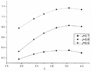
Fig.13 Energy saving effect of fins with different aspect ratios

Fig.14 Energy saving effect of fins with different installation angles
Compared with the calculated results of literatures,the energy-saving effect of a singleenergy-saving device is greater than the effect of it in ESD combination.The hub vortex and the flow field improved gradually make that the energy which is able to be used becomes less and less.
(4)Path lines distribution of the fluid flowing near the twisted rudder
As can be seen in Fig.15,the leading edge shape of twisted rudder changes along with the direction of propeller wake,and this change can absorb part of wake energy.Compared with the twisted rudder with bulb and fins,the path lines distribution of twisted rudder is wider. After installing the bulb and fins,more wake energy is recovered and the open water efficiency is improved.

Fig.15 Path lines distribution of the fluid flowing near the twisted rudder
(5)Axial velocity distribution in the front of twisted rudder
It is the axial velocity distribution of twisted rudder in Fig.16,and the location of the section is at 0.1 m of the X-axis.As can be seen in Fig.16,there is a low-velocity region at the center of the rudder,then the installation of the bulb improves the distribution of flow field.In addition,due to the rectification of the thrust fins,the axial velocity of the fluid passing the fins increases,therefore the thrust force produced by propeller become larger according to the momentum theorem.

Fig.16 Axial velocity distribution in the front of twisted rudder(X=0.1 m)
(6)Pressure distribution of twisted rudder before and after bulb and fins installed
The pressure distribution on the both sides of twisted rudder is shown in Fig.17.Before andafter installation of ESDs,the surface pressure distribution is different,and the low pressure region of twisted rudder shrinks significantly,which is favorable to reducing the cavitation of twisted rudder.

Fig.17 Pressure distribution of twisted rudder before and after bulb and fins installed
5 Conclusions
In this paper,the cavitation tunnel experiment of propeller-rudder system is carried out, and its hydrodynamic performance is calculated.By analyzing the experimental and calculated results,the following conclusions are obtained:
(1)The experimental result shows that the twisted rudder can improve the efficiency of propeller-rudder system.At the design advance coefficient J=0.8,the efficiency of the propulsion system increases by about 2.5%,and the result obtained by CFD is 2.1%.The thrust coefficient KT,torque coefficient KQand open water efficiency η as a function of advance coefficient are calculated,the error of experimental and calculated results is in the acceptable range.Therefore the reliability of this method to forecast the hydrodynamic performance of propeller-rudder system can be proved;
(2)The bulb diameter affects the efficiency of the whole system,and too large or too small bulb will cause the energy-saving effect not ideal.When the diameter ratio of bulb and propeller disk is 0.16,the energy-saving effect is the best.At the design advance coefficient J= 0.8,the efficiency of the propulsion system increases by about 0.94%;
(3)The impact of thrust fins under different parameters on the open water efficiency is studied.After optimizing the fins parameters gradually,the efficiency of the propulsion system increases by 1.20%compared with the system of propeller and twisted rudder;
(4)With the gradual improvement of flow field,the energy which the propulsion system can use becomes less and less,therefore the energy-saving effect of the ESD added afterwards is less than the effect of the same ESD alone;
(5)Comparison between the hydrodynamic performance before and after installation of bulb and fins shows that the bulb and fins not only absorb the energy of propeller wake andimprove the efficiency of the entire system,but also optimize the pressure distribution of twisted rudder surface so that the cavitation on rudder surface can be reduced.
Installation of bulb and fins can improve the efficiency of the entire system and optimize the pressure distribution of twisted rudder surface.The parameters of bulb and fins can be further studied in the future research,and the rudder effect in steering condition should be analyzed to make the selection of parameters more reasonable.
[1]Zhu Xiangyuan,Huang Sheng,Guo Chunyu,Shan Tiebing.Design and performance of a skew rudder behind a propeller [J].Journal of Harbin Engineering University,2008,29(2):126-129.
[2]Wang Chao,He Miao,Wang Guoliang,Guo Chunyu.Design and performance analysis of twisted rudder based on the maximum reduction of rudder resistance[J].Journal of Ship Mechanics,2014,18(3):238-247.
[3]Qi Huibo.A hydrodynam ic performance analysis of skew rudder[D].Harbin:Harbin Engineering University,2011.
[4]He Miao.Design and hydrodynamic performance simulation of integrative energy-saving propulsion system[D].Harbin: Harbin Engineering University,2012.
[5]Yang Bo,Chen Xiaoying,Hu Ping,Zhou Zhanqun.Application of two energy-saving devicesten on thousand tons ship[J]. Marine Energy Saving,2006,9(3):11-13.
[6]Ma Cheng,Qian Zhengfang,Zhang Xu,Du Du.Numeric computation and simulation on the hydrodynamic performance of the propeller-rudder-rudder bubble combination[J].Journal of Ship Mechanics,2005,9(5):38-45.
[7]Liu Yebao,Su Yumin,Shen Hailong,Ju Lei.Study on energy-saving rudder bulb fin combination based on surface panel method[J].Journal of Shanghai JiaoTong University,2012,46(3):374-378.
[8]Sanchez C A,Rautaheimo P,Siikonen T.Simulation of incompressible viscous flow around a propeller using a RANS equation solver[C]//Twenty-third Symposium on Naval Hydrodynamics.France,2000.
[9]Sanchez C A,Ory E,Salminen E,et al.Simulation of incompressible viscous flow around a tractor thruster in model and full scale[C]//Eighth International Conference on Numerical Ship Hydrodynamics.Korea,2003.
[10]Hsin C Y,Wu J L,Chang S F.Design and optimization method for a two-dimensional hydrofoil[C]//Conference of Global Chinese Scholars on Hydrodynamics,July,2006.Shanghai,China,2006:323-329.
[11]Takayuki W,Takafumi K,Yoshihisa T,et al.Simulation of steady and unsteady cavitation on a marine propeller using a RANS CFD code[C]//Fifth International Symposium on Cavitation,November,2003.Osaka,Japan,2003.
[12]Park W G,Jung Y R,Kim C K.Numerical flow analysis of single-stage ducted marine propulsor[J].Ocean Engineering, 2005(32):1260-1277.
[13]Lee KyungJun,Bae JoonHwan,Kim Hee-Taek,et al.A performance study on the energy recovering turbine behind a marine propeller[J].Ocean Engineering,2014(91):152-158.
[14]Wang Junfu.Computational fluid dynamics analysis-CFD software principles and applications[M].Beijing:Tsinghua University Press,2004.
[15]Gao Fudong,Pan Cunyun,Cai Wenshan,Yang Zheng.Numerical analysis and validation of propeller open-water performance based on CFD[J].Journal of Mechanical Engineering,2010,46(8):133-139.
摘要:文章對槳后普通舵和扭曲舵的水動力性能進行了試驗研究,并采用計算流體力學方法對槳舵系統的水動力性能進行計算,得到了不同進速系數下的推力系數、扭矩系數以及敞水效率,并繪制了敞水性能曲線。通過槳舵模型試驗值與計算值的對比,驗證了計算方法的可靠性。為了進一步提高扭曲舵的節能效果,在扭曲舵前安裝了舵球,優化舵球的半徑后在舵球兩端安裝推力鰭,通過優選推力鰭的各個參數(安裝位置、展弦比和安裝角),使槳舵系統的敞水效率逐步提高。確定了舵球鰭的最優參數后,槳—扭曲舵系統的效率進一步提高1.2%。最后通過觀察舵表面壓力分布、舵附近軸向速度和跡線分布,分析了舵球鰭對槳舵干擾的影響。
舵球鰭參數對扭曲舵水動力性能的影響研究
孫瑜,蘇玉民,胡海洲
(哈爾濱工程大學水下機器人技術國防科技重點實驗室,哈爾濱150001)
扭曲舵;水動力性能;舵球;推力鰭;計算流體力學
U664.36
A
孫瑜(1988-),男,哈爾濱工程大學博士研究生;蘇玉民(1960-),男,哈爾濱工程大學教授,博士生導師;胡海洲(1989-),男,哈爾濱工程大學碩士研究生。
U664.36
A
10.3969/j.issn.1007-7294.2016.09.001
1007-7294(2016)09-1071-12
Received date:2016-02-02
Foundation item:Supported by the National Natural Science Foundation of China(Grant No.51479039,Grant No. 51009038);the China Postdoctoral Science Foundation(Grant No.2013M 540271);Fundamental Research Funds for the Central Universities(Grant No.HEUCFD1403)
Biography:SUN Yu(1988-),male,Ph.D.student of Harbin Engineering University,E-mail:sunyu1716@hrbeu.edu.cn; SU Yu-min(1960-),male,professor/tutor.
- 船舶力學的其它文章
- Recent Progress in Hydrodynam ic M odel Test for Two Floating Bodies at Close Proxim ity in W aves
- Numerical Analysis of Load-noise of a Highly-skewed Propeller behind Subm arine
- Comparison of Different Finite Element Modeling M ethods for the Soil-Pile Interaction of Jack-up Platform
- Vibration due to Propeller-Shaft-Hull Coupling of a SWATH
- Structural Strength Evaluating M ethod of the Azimuth Thruster Propeller Blade
- Application of Inertia Relief in the Prediction of W elding Deformation for Large Complex Structures