Control system design of flying-wing UAV based on nonlinear methodology
2017-12-20 03:04:49JigungLIXinCHENjunLIRongZHANGSchoolofAutomtionNnjingUniversityofAeronuticsAstronuticsNnjingJingsu210016ChinSchoolofElectronicEngineeringNnJingXioZhungUniversityNnjing211171Chin
Defence Technology 2017年6期
Ji-gung LI,Xin CHEN,Y-jun LI,Rong ZHANGSchool of Automtion,Nnjing University of Aeronutics&Astronutics,Nnjing,Jingsu,210016 ChinSchool of Electronic Engineering,NnJing XioZhung University,Nnjing,211171 Chin
Control system design of flying-wing UAV based on nonlinear methodology
Ji-guang LIa,*,Xin CHENa,Ya-juan LIb,Rong ZHANGaaSchool of Automation,Nanjing University of Aeronautics&Astronautics,Nanjing,Jiangsu,210016 China
bSchool of Electronic Engineering,NanJing XiaoZhuang University,Nanjing,211171 China
In this paper,A fluid vector rudder flying-wing UAV is employed as the design object,so as to study the nonlinear design method and flight validation.For the maneuvering flight control,this paper presents a control structure.This control structure included the inner loop linearization decoupling methods to eliminate the known negative coupling and the outer loop backstepping methods for trajectory tracking control.The stability of the control structure has been proved in this paper.Compared with the traditional backstepping control method,this controller increases the inner loop decoupling structure and retains the aerodynamic damping term which makes the linearized system a weak nonlinear system.This structure can not only reduce the conservatism of the outer loop controller design,but also is convenient for engineering implementation.Simulation and flight validation results show that the proposed control scheme is effective.
1.Introduction
With the wide application of the UAV and extension of the mission requirements,maneuver ability gradually becomes the basic performance of the UAV[1-3].The ability of maneuver flight not only helps the UAV to evade the land-based air defense,thus improving the survivability of the UAV in the battlefield,but it is also the basic guarantee for carrying out the surveillance and attack of the fast moving target,thus intercepting cruise missile and landing on board the ship[4,5].
Compared with the conventional aircraft,flying-wing aircraft has advantages on structural strength,aerodynamic and stealth aspects,but it is not suitable for maneuvering flight[6-8].Flyingwing aircraft canceled the tail,thus weakening the course stability.In addition,the short arm of force leads to the condition that the pneumatic rudder control efficiency is not enough.Before the vector control technology has been applied,these limiting factors result in that the flying-wing UAV does not have the ability of maneuvering flight.In recent years,with the development of vector control technology and control theory,as well as the demand for combat environment,the maneuver ability of flying-wing UAV has attracted unprecedented attentions[9,10].
In designing the control system,because of the special aerodynamic configuration,the coupling between longitudinal and lateral channel in maneuvering flight of the flying-wing UAV is more serious than that in conventional aircraft.At the same time,the complex nonlinearity,hysteresis effect,uncertain disturbances and other problems make the maneuvering control of flying-wing UAV difficult to achieve[11-13].The characteristics of nonlinearity,unsteadiness and strong coupling involved in UAV maneuvering flight result in the lack of typical equilibrium state.The traditional linear control method based on the equilibrium point of the small disturbance linearization is facing a serious challenge[13-15].When the flying-wing UAV is maneuvering at large attack angles,there are problems of nonlinearity,unsteadiness,and strong coupling as well as unsteady effects of mass inability to model and disturbance.It is very difficult for the conventional controller to meet the flight performance requirements.Thus,we need to study a system design method that has strong robustness in accordance with the dynamical features of flying-wing UAVs.Good robust stability and the desired flying qualities are guaranteed in the situation of nonlinearity,strong coupling and model uncertainty.
Maneuver control is typically a matter of nonlinear closed-loop stability augmentation control,and its main issue is to eliminate the effect of nonlinearity as well as the design the calculationproblems of the controller.In recent years,the rapid development of linearization theory,such as dynamic inversion method,has opened the way for the development of the modern design of nonlinear systems.Literature[16-23]studied the problems of the nonlinear control method applied in the flight control design,which were verified by practical flight test.
Known from the above literature,the nonlinear control method represented by the dynamic inversion method has made full recognition and development for solving the problem of nonlinear closed-loop stability augmentation control.The main idea of dynamic inversion method is to eliminate the nonlinear influence through the inverse controller,thus enabling the inner loop dynamics of theUAV topresentthe characteristics of the linearsystem(or approximate linear system).
According to the processing power of the airborne electronic device,this paper presents a control scheme that uses the inner loop linearization decoupling methods to eliminate the known negative coupling,the outer loop backstepping methods for trajectory tracking control.The stability of the control structure has been proved in this paper.Compared with the traditional backstepping control method,this controller increases the inner loop decoupling structure and retains the aerodynamic damping term which makes the linearized system a weak nonlinear system.The structure can not only reduce the conservatism of the outer loop controller design,but also is convenient for engineering implementation.It is validated to be effective design method through l ying-wing UAV flight test.
Nomenclature
fTthe thrust of the one fan
l1the distance of the vector rudder along with fuselage direction to the center of gravity
δrthe angle of vector rudder
MAthe torque generated by aerodynamic forces
Iinertia matrix
S(ω) ω's anti symmetric matrix
Θinominal value
ΔΘiperturbation value
f0the inertial coupling torque
Kthe damping torque coefficient nominal value of each channel
ulinthe control input to design the outer controller
??,?ζthe output of the ideal weight matrix of the outer controller
?*,ζ*the output of the adaptive law f
2.The flight test flying wing UAV
In this paper,the study of flying-wing UAV have thrust vectoring rudder.The UAV and rudder surface as shown in Fig.1(a)and Fig.1(b).
As shown in the above figures,the UAV is powered by a ducted fan.An adjustable bezel is mounted on the air outlet of the duct,which is used to change the direction of air flow to provide yaw moment and named vector rudder.Two pieces of vector rudder can only be deflected in the same direction.However,due to the layout,twovector rudderonlyonecan deflection for middleof the fuselage and change the direction of airflow.A piece of elevon on the back of wing.
3.Aerodynamic modeling
Since the UAV using a special vector rudder,the function of vector rudder is modeling firstly here.Definition:The thrust of the one fan isfT;the distance isl1which the vector rudder along the fuselage directiontothe centerof gravity;Deflection angle of vector rudder isδr.Assuming that the air flows along the bezel,then the lateralforce and yaw moment generatedbythe vector rudderare as follows
This paper presents a controller fora nonlinear flying-wing UAV.The body- fixed axes,and nonlinear equations of motion for a flying-wing UAV over a flat earth are given by
Define the state vectors as follows
Definex4= [x1,x2]T,x5= [x2,x3]T,and the fight dynamic equations(3)-(5)can be rearranged as
In order to express the inner loop decoupling design conveniently,the attitude equation of the UAV is presented as
4.Structural design of the controller
Compared with the conventional layout of the aircraft,the coupling effect of the flying-wing UAV is more serious.Moreover,the flying-wing UAV is unstable and its rudder operation is ineff icient.These factors make it difficult for the flying-wing UAV to guarantee the quality in the maneuver flight.
In the traditional dynamic inverse decoupling control method,it is expected to eliminate all the nonlinear terms in the UAV dynamic model through the state feedback.These nonlinear terms include aerodynamic force/torque term,inertial coupling term,gravity term and other uncertain terms caused by various disturbances.Some of these terms show very strong nonlinear features,such as the inertial coupling,etc.,which must be linearized for the design of the controller.But the damping term in the aerodynamic torque reflects the inherent damping characteristic of the UAV,which is beneficial tothe stabilityof the dynamic performance of the control system.Therefore,there is no need to eliminate the coupling of this part.Thus,in the process of inverse system design,the damping term can be reserved to obtain the weakly non-linear system by non-linear compensation.This system is a pseudo linear system of time-varying parameters.By retaining the aerodynamic damping characteristics of part of the system,this method that uses the robust control method for further design of the outer loop controller can not only reduce the conservatism of the controller design,but also be easy for engineering realization.Based on this idea,this paper designs the controller structure as shown in Fig.2.
In the controller structure shown in Fig.2,the aerodynamic database,torque compensation module,torque allocation module and UAV dynamic model comprise the pseudo control object.The linear controller and the pseudo control object connect in series and form a closed loop system that is also a weakly nonlinear system.The closed-loop system is compensated by the robust controller so as to adjust the output error of the ideal model.Thus,the sensitivity problem of the inverse system to the modeling error can be solved.
The following is the control process of the system:Firstly,according to the current flight status of UAV,the control input is obtained by linear modular to eliminate the non-linear and unsteady aerodynamic torque and inertia coupling torque,and the pseudolinearsystem isobtained bythereal-timetorque compensation.Then,a linear controller is designed for the compensated linear system on the control law.Finally,through utilizing the expected reference model,the closed-loop controller of the flight quality and flight performance is designed by the robust control compensator,which enables the system to have a good operation stability.
5.Linearization decoupling of attitude equations
5.1.Inner loop torque compensation
According to the previous discussion,it can be seen that the decoupling linearization but retaining aerodynamic damping torque can bring many benefits.Therefore,this section will introduce the method of torque compensation and retaining the aerodynamic damping torque.For the controller structure of Fig.2,a more detailed structure of the inner loop nonlinear decoupling controller is shown in Fig.3:
In order to express conveniently,the attitude equation of the flying wing UAV is expressed as follows
Where: ω = [p,q,r]T,MAis the torque generated by aerodynamic forces.IandS(ω)are inertia matrix and ω's anti symmetric matrix
Aerodynamic moments in formula(8)can be expressed as
Assuming that the aerodynamic moment coefficient and the engine thrust are nonlinear function with time varying parameters
Taking formula(10)into formula(8),and we get
The nominal model of the system can be expressed as
As the damping torque re flects the inherent damping characteristics of the UAV,this part of the torque should be retained in the aerodynamic compensation process.The compensation torque can be expressed as:
The influence of the inertia coupling torque and the cross coupling torque between the channels can be compensated by the above formula.The coupling between the channels can be avoided when the UAV is maneuvering with large angular velocity.
Taking formula(10)into formula(9),and we get
From the equation(14),we can see that the compensation method finally obtains a first-order inertia link.This inertial link retains the inherent damping characteristics of the system.Withulinas the control input to design the outer controller,it can be ensuredthatthesystem couldhaveabetterclosed loop performance.
5.2.Linearization of attitude equations
In order to make the system to have a better response to the instruction,the attitude equation of the UAV is linearized to eliminate the influence of the motion coupling in this paper.Herein,the method of input-output linearization based on Lie derivative is presented.The steps of the system linearization are as follows:
(1)Select the coordinate transformation function set
which is defined in the neighborhoodxo.
(2)The system is transformed into m groups of equations:
After the above coordinate transformation and state feedback,the original system is transformed into a Brunovsky standard system
The affine non-linear system can be transformed into a standard linear system with the above steps.However,the calculation process is not always easy,especially for the matrix A-1.in formula(19).But it is not difficult to get the analytic formula of the matrix A.Fortunately,the solution of matrix A-1is not necessary.In the actual simulation design,it is not in accordance with the above steps:first is the coordinate transformation,and then state feedback to get the state of the system after the transformation.Afterwards,the original system state can be obtained by inverse coordinate transformation.In practical application,the process of coordinate transformation is totally unnecessary.Only by state feedback can the decoupling of the original system be achieved.Such a design avoids the solution of the matrix A-1and some unnecessary coordinate transformations.If the state of the linear system after transformation is required,it can be obtained by coordinate transformation of the original system.
According to formula(13),the coordinate transformation function of the system is obtained
with formula(16),
For the convenience of expressing the design of the outer-loop controller in the following passage,the post-decoupled attitude equation and the trajectory equation are expressed as follows and named as System 1 and System 2.
Where, state vectorx1,x2,x3,u∈R3, andx1= [α,β,φ]T,
x2= [p,q,r]T,x3= [φ,θ,ψ]T,u= [δe,δa,δr,δT]T,x4= [x1,x2]T.
6.Design of outer loop controller
The purpose of the outer loop control is to achieve the tracking ofα,β,φ input commands.The outer loop controller is based on the current state of the aircraft and the adaptive law of the input U to output,so that the outputx1of the system can asymptotically track the desired reference inputx1d.
Leading the derivative of the above formulas,and taking them into formulas(4)and(5),the closed-loop error state equations are as followed
Known from above two formulas
Define the ideal control variable of the system Z1 as
wherek1>0 is the controller design parameter.Because ?*is unknown,the estimated value?? is used here.Hence the actual virtual control input for the system is obtained
Taking formula(30)into formula(28),and we get
According to formula(27),the ideal control input of the system is defined as
Taking them into formula(27),we can obtain
7.Controller stability analysis
In order to analyze the stability of the system,we select the following Lyapunov function
The ?*and ζ*are expressed in the form of a partitioned matrix,and then the above formula(35)can be expressed as
Taking the derivative of the above functionV(t)over time t,and we will obtain
The adaptive law of the particle swarm is expressed as followed
Since the following inequalities are established
Define ρ=min{2k10,2k20,αi,βi},and formula(40)can be expressed as
Following are the theorem and the process of proof.
(1)the statex(t)=[xT1,xT2]Tof the closed-loop system and the adaptive weight??,?ζis bounded:
the state of the system and the exponential convergence of the compensator are convergent to a bounded compact setΩs,and
Conclusion 1 can be proven as follows
Integrate both sides of formula(41)from[0,t],and we can obtain
Depending on the above formula and formula(36)
From the above two formulas,formulas(42)and(43)can be obtained.
Becausez1,z2,x1dare bounded ande t()=x1t()-xdt(),the following formula is available
Thant is,formula(44)sets up,and conclusion 1 is proved.Conclusion 2 can be proven as follows:From formula(48)and(49)we can obtain
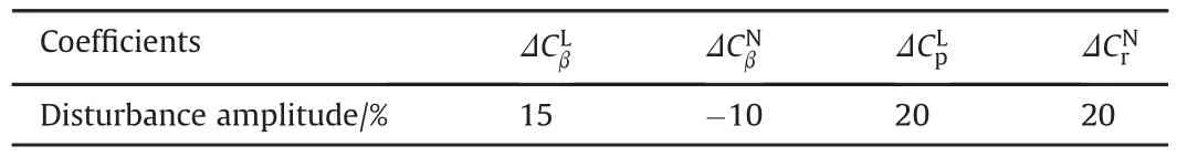
Table 1Aerodynamic disturbance coefficients.
The conclusion 2 is proved.
From formula(45),we can know that by adjusting the magnitudes of thek10,k20,λ1,αi,λ2,βi,the convergence rate and the domain of the convergence of the system can be adjusted.
8.Simulation and flight validation
It is known from the above control law design that the purpose of control is to track the α,β,φ.However,due to the airborne equipment can not directly measure the signals of attack angle and sideslip angle,the acceleration and GPS velocity signals are used to calculate the required air flow angle.The calculating formulas are
In order to verify the robustness of the controller,the aerodynamic disturbance coefficients are selected in the maneuver process.The amplitude of disturbance is shown in the table(see Table 1):
In this paper,we choose the spiral isokinetic drop maneuver and the continuous rapid of one flying-wing UAV to Simulation toverify the performance of the designed controller.In the following of maneuver simulation results,the red solid lines represent the aerodynamic coefficients without disturbance while the black dashed lines represent the aerodynamic coefficient with disturbance.
Spiral maneuvering is commonly used in UAV tracking target.In general,the speed of the UAV is greater than the speed of the tracking target motion.In order not to lose track of the target,the UAV often needs to spiral over the target.Spiral isokinetic maneuvering is to reduce the flying height on the basis of the spiral maneuver,and maintain the same flight speed.The maneuver not only requires the UAV to have a good course stability,coordination of turning ability,track tracking capability,but also increases the throttle control to maintain kinetic energy.The simulation results are shown as follows:
From Fig.4,we can see that the flying-wing UAV has been reduced its height from1500 m to 500 m at the same speed.Flyingwing UAV has no side-slip phenomenon.With/without disturbances,it can be seen that the flying-wing UAV can follow flight instructions in the presence of disturbances.The system has good adaptability to disturbance.
Typical maneuver action in the flight test process are as follows.Flying wing UAV Ranversman maneuver trajectory and attitude as shown in Fig.5.
It can be seen from the flight test results that:the energy of the flying-wing UAV is rapidly transformed from the kinetic energy to the potential energy,and the direction of the nose pointing is changed.It can be known from the attitude figure that the turning process of the flying-wing UAV is coordinated.
Another continuous maneuver flight is also shown in Fig.6.Its combined maneuver flight process is described as follows:Flying-wing UAV climbs rapidly to occupy the height advantage,so as transform the kinetic energy into potential energy,while changing the nose pointing.The Flying-wing UAV began to dive when the potential energy is the maximum,making the potential energy to be translated into kinetic energy and saving energy for the next maneuver flight.When the new flight mode is established,the Flying-wing UAV immediately jumps and turns,with its the nose pointing changing 180°.The continuous maneuver flight is equivalent to have an Immelmann maneuver followed by a Ranversman maneuver.The trajectory and attitude is shown in Fig.6.
From Fig.6,we can see that,during the flight,the attitude and flight state of UAV is stable.As can be seen from the attitude,the veri fication UAV longitudinal channel and lateral channel is decoupled.The flight test show that the controller designed in this paper is effective.
9.Conclusion
With a fluid vector rudder flying-wing UAV as the designed object,this paper has studied the nonlinear design method and done the flight validation.According to maneuvering flight control of flying-wing UAV faces the problem of nonlinearity,unsteadiness and strong coupling,this paper presents a control scheme that uses the inner loop linearization decoupling methods to eliminate the known negative coupling,the outer loop backstepping methods for trajectory tracking control.The stability of the control structure is proved in this paper.Compared with the traditional backstepping control method,the controller increases the inner loop decoupling structure.and retains the aerodynamic damping term in the control structure,which makes the linearized system a weak nonlinear system.The structure can not only reduce the conservatism of the outer loop controller design,but also is convenient for engineering implementation.Simulation results show that the proposed control scheme is effective.
The control process of the system is as follows:Firstly,according to the current flight status of UAV,the control input is obtained by linear modular to eliminate the non-linear and unsteady aerodynamic torque and the inertia coupling torque,and a pseudo linear system is obtained by the real time torque compensation.Then,a linear controller is designed to the compensated pseudo linear system.Finally,by using the expected reference model,the closed-loop controller of the flight quality and flight performance is designed with one robust control compensator,which makes the system to have good operation stability.From the snake maneuver simulation results,the design scheme is proved to be effective.The flight test indicates that the proposed control scheme is effective.
[1]L.C.Edward,Longitudinal and lateral-directional coupling effects on nonlinear unsteady aerodynamic modeling form flight data[J],AIAA atmospheric flight mechanics conference and Exhibit,Monterey,CA,5-8Aug2002.
[2]Alikhan Mir,Naba K,Peyada,Go TiauwHiong.Flight dynamics and optimization ofthree-dimensionalperchingmaneuver.JGuid ControlDyn 2013;36(6):1791-6.
[3]Guo Yang,Yao Yu,Wang Shicheng.Maneuver control stratergies to maximaze prediction errors in ballistic middle phase.J Guid Control Dyn 2013;36(4):1225-34.
[4]Zhi Qiang,Cai Yuanli.Energy-management steering maneuver for thrust vecor-controlled interceptors.J Guid Control Dyn 2012;35(6):1798-804.
[5]Mueller JB,Paul R.Avoidance maneuver and planning incorporating stationkeeping constraints and automatic relaxation.J Aerosp Inf Syst 2013;10(6):306-22.
[6]Andrew JN,Fernando NU,John Y.Performance studies of shock vector control Iluidic thrust vectoring[R].AIAA 2007:2007-5086.
[7]Karen AD.Summary of fluidic thrust vectoring research conducted at NASA langley research center[R].AIAA-2003-3800.2003.
[8]Sadiq MU.Performance analysis and flowfield characterization of secondary injection thrust vector control(SITVC)for a 2DCD nozzle[D].Los Angeles:University of Southern California;2007.
[9]Mengjie WAND,Eriqitai,Qiang WAND.Numerical simulaton of nozzle pressure ratio effect on vector Performance and separation control for shock vector control nozzle.J Aerosp Power 2015;30(3):527-38.
[10]Kiranyaz S,Ince T,Gabbouj M.Dynamic data clustering using stochastic approximation driven multi-dimensional particle swarm optimization.Lect Notes Comput Sci 2010;22(10):1448-62.
[11]Yang Yi,Chen Xin.Transient performance improvement in model reference adaptive control using h? optimal method.J Frankl Inst 2015;(352):16-32.
[12]Yang Yi,Chen Xin.Transient performance improvement in model reference adaptive control using h? optimal method.J Frankl Inst 2015;(352):16-32.
[13]Zhu Jihong,Zhang Shangmin,et al.Dynamic characteristics and challenges for control system of super-maneuverable aircraft.Control Theory&Appl 2014;31(12):1650-62.
[14]Wilson JR.UAV worldwide roundup.Aerosp Am 2005;43(9):26-34.
[15]Osterhuber R.FCS requirements for combat aircraft-lessons learned for future Designs.STO-AVT-189.In:Workshop on Stability&Control,Portsmouth;October 2011.p.23-5.
[16]van Soest WR,Chu QP.Combined feedback linearization and constrained model predictive control for entry flight.J Guid Control Dyn 2006;29(2):427-34.
[17]Sonneveldt L,Chu QP.Nonlinear flight control design using constrained adaptive backstepping.J Guid Control Dyn 2007;30(2):322-36.
[18]Lee Taeyoung,Kim Youdan.Nonlinear adaptive flight control using backstepping and neural networks controller.J Guid Control Dyn 2001;24(5):675-83.
[19]Sieberling S,Chu QP.Robust flight control using incremental nonlinear dynamic inversion and angular acceleration prediction.J Guid Control Dyn 2010;33(6):1732-42.
[20]MacKunis W,Patre PM.Asymptotic tracking for aircraft via robust and adaptive dynamic inversion methods.IEEE Trans CONTROL Syst Technol 2010;18(6):1448-56.
[21]Johnson Eric N,Michael A.Turbe.Modeling,control,and flight testing of a small ducted-fan aircraft.J Guid Control Dyn 2006;29(4):769-80.
[22]Xu Bin,Huang Xiyuan,Wang Danwei.Dynamic surface control of constrained hypersonic flight models with parameter estimation and actuator compensation.Asian J Control 2014;16(1):162-74.
[23]Li Jiguang,Chen Xin,et al.,Control system design study of nonlinear robust Method on Flying wing UAV,J Beijing Univ Aeronautics Astronautics,2017-05-31,Network first publishing.
29 November 2016
in revised form 31 May 2017 Accepted 14 June 2017 Available online 20 June 2017
?2017 Published by Elsevier Ltd.This is an open access article under the CC BY-NC-ND license(http://creativecommons.org/licenses/by-nc-nd/4.0/).
*Corresponding author.
E-mail address:912646963@qq.com(J.-g.LI).
Peer review under responsibility of China Ordnance Society.

- Defence Technology的其它文章
- Influence of electric current intensity on the performance of electroformed copper liner for shaped charge application
- Split warhead simultaneous impact
- Effects of Al/O on pressure properties of confined explosion from aluminized explosives
- The effect of wax coating,aluminum and ammonium perchlorate on impact sensitivity of HMX
- Microstructural observations on the terminal penetration of long rod projectile
- Spectrally adapted red flare tracers with superior spectral performance