Achieving thermal magnification by using effective thermal conductivity
2018-07-27 07:37:10QingxingJiGuodongFngJunLing
Qingxing Ji, Guodong Fng, Jun Ling*
a Center for Composite Materials, Harbin Institute of Technology, Harbin, 150001, China
b Institute of Advanced Structure Technology, Beijing Institute of Technology, No.5 South Zhongguancun Street, Haidian District, Beijing,100081, China
Keywords:
ABSTRACT A thermal magnification device is proposed by using effective thermal conductivity. Different from transformation optics method, the magnification design is realized analytically by enforcing equality of effective thermal conductivity on the magnification device and the reference case in specified domains. The validity of theoretical analysis is checked by numerical simulation results,which demonstrates the magnifying effects of the proposed design. The device only needs isotropic and homogeneous materials that are easy to obtain in nature. It is also shown that the obtained magnifying conditions are the same as those derived by separation of variables. But the proposed method proves more flexible for multilayered materials and simpler for non-spherical objects under non-uniform thermal fields. It can also be extended to other fields and applications governed by Laplace equation.
Transformation optics theory was first proposed by Pendry and Leonhardt [1, 2] in the field of achieving invisibility of electromagnetic waves. Since then transformation optics aroused extensive interests and there had been significant progress in theoretical and experimental approaches in many fields, including acoustics [3-5], magnetic field [6-8], elastic wave [9, 10], matter waves [11, 12] and thermodynamics [13-16]. Among the various applications, the most famous work was the invisible cloak which bent the light around the concealed area and made an object invisible to the observer. Later the concept of cloaking was extended. Lai et al. [17] proposed the concept of illusion optics which made an object of arbitrary shape and material properties appear exactly like another object of some other shape and material makeup. Then, the illusion device was experimentally demonstrated [18-21]. An invisible gateway was first experimentally realized by using a transmission-line medium [18]. Later on,dc illusion devices [19], radar ghost illusion devices [20], and acoustic illusion devices [21] were respectively proposed and verified experimentally by similar methods.
The illusion devices were designed to make a target image misleading due to physiological illusion or a specific visual trick,while a magnification device could change the original object into a larger one to a detector. The magnification device was indeed an application of illusion optics [22-25]. The first magnification device known as a super scatter was proposed by Yang et al. [22] based on the concept of complementary media. Such a device could enhance the electromagnetic wave scattering cross section of an object so that it behaved like a scatter bigger than the scale of the device. However, the device was realized by a negative refractive material shell that was difficult to implement experimentally [26, 27]. Xu et al. [28] first verified the super scatter by experiments where only anisotropic and inhomogeneous media with positive components were required. In his experiment, combination of compact electric and magnetic resonance particles was used to fulfill anisotropic and inhomogeneous materials requirements.
It has been proved that the anisotropic and inhomogeneous materials required by transformation optics method were difficult even impossible to realize exactly in practical. Many works[29-34] have been done in designing magnification devices with isotropic and homogeneous materials based on the method of separation of variables. This letter proposed a magnification designing method with the concept of effective thermal conductivity. The results of the proposed method showed good agreement with the works by Mei et al. [33, 34]. Compared with Mei’s works, the method in this letter was simpler and more effective without solving Laplace equation. For non-spherical objects and non-uniform thermal fields, the proposed method showed more flexibility and convenience. In addition, separation of variables would be more complicated for multiple conducting layer materials, while more layers offered more adjustable design variables such as the thickness and conductivity of each layer. The proposed method could be applied not only to thermodynamics but also to other fields governed by Laplace equation.
An intuitive schematic diagram was illustrated in Fig. 1 to show the working principle of the magnification device. Without losing generality, the original object was supposed to be a round one with radiusand thermal conductivity. When embedded in the background medium, the original object was detected. However, if the object was wrapped by a designed coating layer with thicknessand conductivity, it will be wrongly identified as another one with different size and conductivity to the observers. In fact, the wrapped object will not be detected as an object with radiusbut as an enlarged one with radiusand conductivity. In this case, the original object was magnified to the observers, and a kind of illusion was thus obtained. To quantitatively demonstrate the magnifying effect,the magnifying factor was defined as[33, 34].
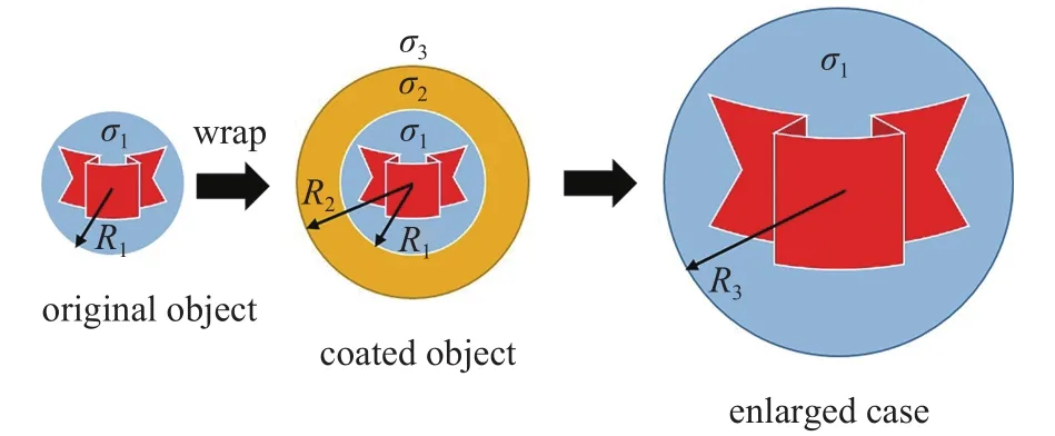
Fig. 1. The working principle of a thermal magnification device.
In Mei’s works [33, 34], the method of separation of variables was used, and theoretical temperature distribution was obtained. By enforcing equality of temperatures on the sameboundary, the external temperature distribution became identical. In this letter, the method of effective thermal conductivity was employed to achieve the magnifying effect. In the following, Hashin-Shtrikman formula [35, 36] was introduced and then applied to the design of thermal magnification device. The effective thermal conductivity of the isotropic multilayered spheres could be estimated by
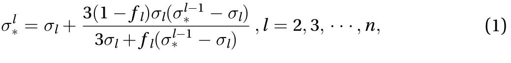
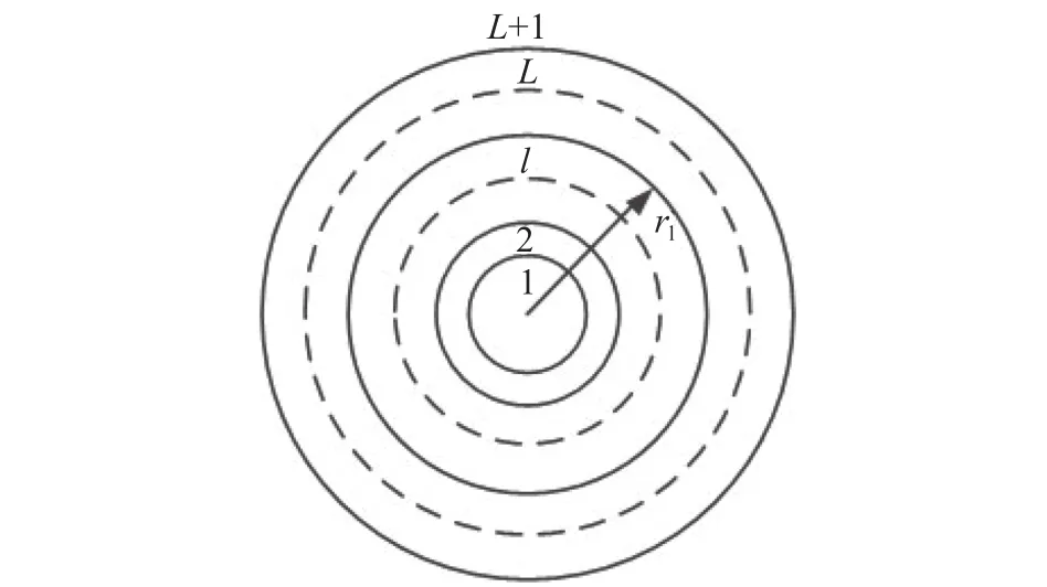
Fig. 2. The cross-section configuration of a multilayered sphere.

When Eq. (1) was extended to cylindrical objects,was achieved by

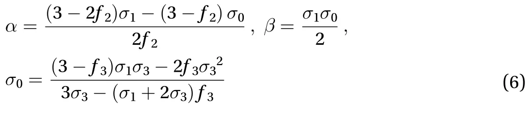
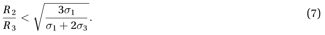
It was shown in Fig. 1 that temperature distribution in the regionshould be identical for the coated object and the reference case. Thus, the effective thermal conductivity of the domainfor the coated object should be same to the enlarged case. The magnification condition for the three-layered sphere could be obtained by

It should be noted that the device was a coated sphere(). The 3th layer, which was part of the background medium, was indeed virtual and self-defined. The three layers referred to the original object, the coating layer
where
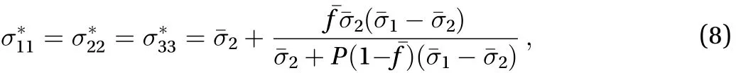
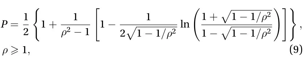
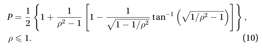
The working principle and proposed method were also applicable to non-spherical objects, including the spheroids. Due to the shape asymmetry, the overall properties of the coated spheroid may be anisotropic if the core and coating were all isotropic. To obtain a coated ellipsoid with isotropic parameters,geometric conformal coating was adopted. In the Cartesian system, the semi-axis of the spheroid core, coating and matrix layer were denoted by,and(for the core,for the coating andfor the matrix layer), respectively, wherewas the aspect ratio of the spheroid. An isotropic core of thermal conductivitywas used, and it was covered with a coating of isotropic conductivity. The effective thermal conductivity tensor could be given bywhere
where
was a constant determined by
and
.Equation (8) denoted that the assemblage of conformal spheroid core and coating with isotropic conductivities remained isotropic [35, 36]. For prolate spheroids,
and for oblate spheroids,
The relationship between the parametersandwas illustrated in Fig. 3. It was easy to check that Eq. (1) could be recovered when, noting thatfor this case.
Similar to the working principle and method of multilayered spheres, an ellipsoidal magnification device could be achieved by enabling the effective thermal conductivity of the threelayered ellipsoid system exactly equal to that of the enlarged object, as demonstrated by following equation:
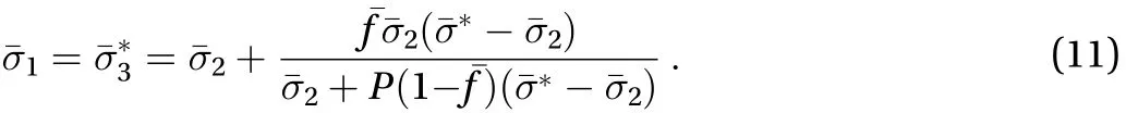
In this part, the conductivitywas predefined, and the radiuswas the design variable.
Combining Eqs. (8) and (11) and discarding the negative value, thep parameterwas determined by
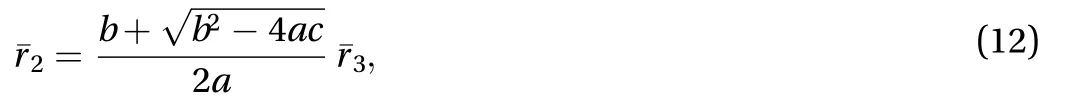
where,
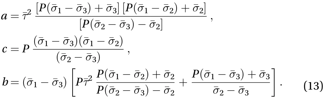

Fig. 3. The relationship between the parameter and. The selected value in the simulation was marked out.

To validate the proposed design, some numerical simulations based on the commercial software COMSOL Multiphysics were conducted. In the simulation, the parameters were set aswhich denoted a magnifying factor. The ratio between outer and inner radius of the coated object was defined as. The parameterwas chosen to be 2.6, namelyin this case. The thermal conductivities of the core and background materials were respect-to check that the obtained parameters above satisfied the constraints imposed by Eq. (7). The relationship between the magnifying factorand corresponding thermal conductivityfor different parameterwas plotted in Fig. 4. The selected parameter value was also marked out in Fig. 4.
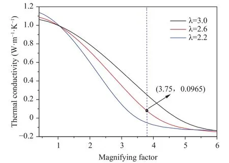
Fig. 4. The relationship between the parameter and. The selected value in the simulation was marked out in the Figure.
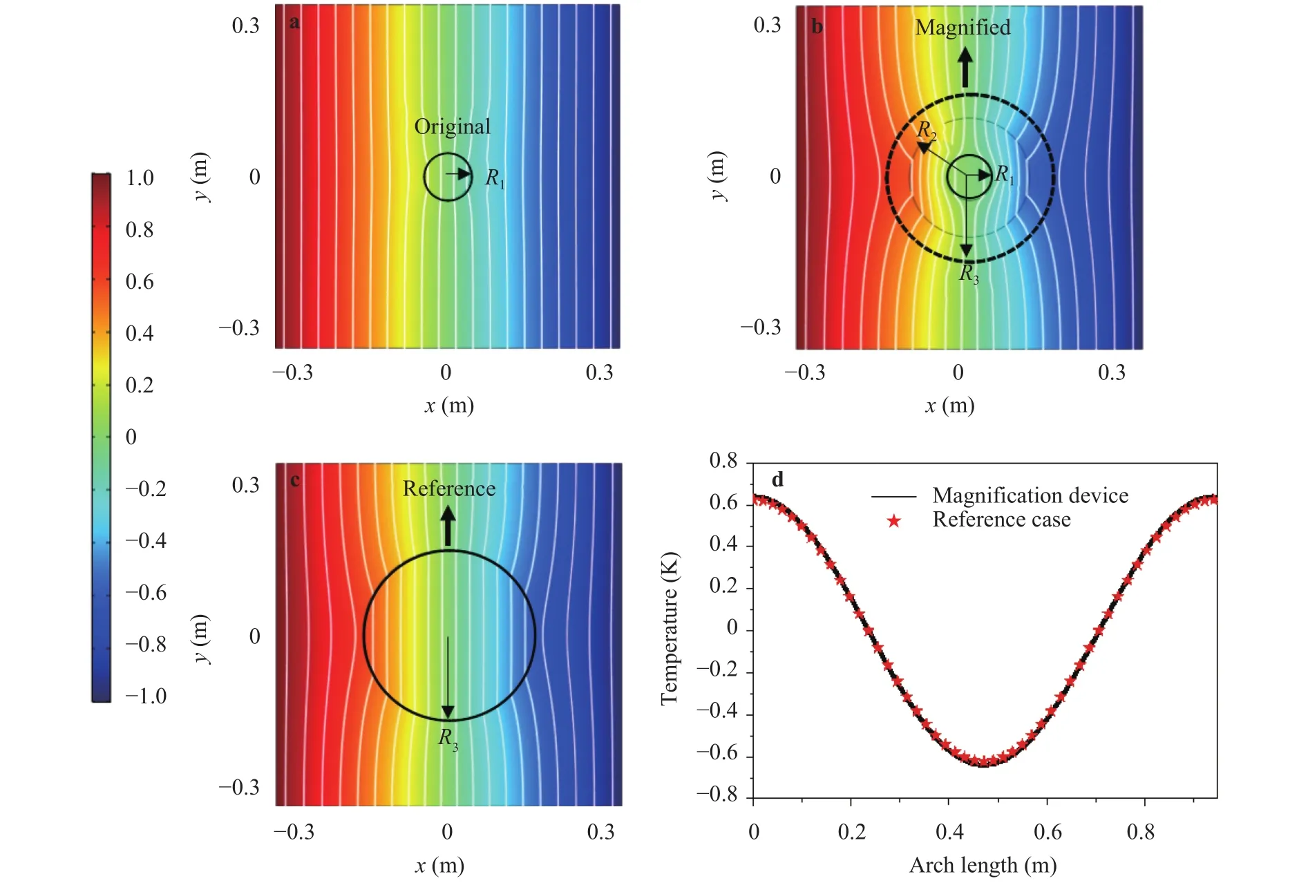
Fig. 5. Simulation results for the thermal magnification device. The white lines represent iso-temperature lines. a The temperature distribution of the original object. b The temperature distribution of the designed magnification device. c The temperature distribution of the reference case.d A quantitative demonstration of equivalence of the temperature on specified boundary.
The simulation results were shown in Fig. 5, where the temperature of the left and right boundary were 1 K and -1 K, respectively. The top and bottom surfaces were used as insulators.Figure 5(a) showed the temperature distribution of the original object embedded in the background material. The object had a radiusand thermal conductivity. It was seen that the uniform temperature field was disturbed around the object and isotemperature lines bent inwards the object. Figure 5(b) displayed the temperature distribution for the original object wrapped with the designed shell. The dotted circle revealed the position of the virtual boundary. To give an intuitive comparison,the corresponding reference case was presented in Fig. 5(c)where only the enlarged object with a radius R3and thermal conductivityexisted in the background. It was shown that the temperature distribution in the regionin Fig. 5(b) resembled that in Fig. 5(c). Fig. 5(d) showed the temperature distribution on the circular boundary () for the two cases in Fig. 5(b) and Fig. 5(c), which indicated quantitative equivalence between them. When it was detected, the original objectwill be magnified as the illusion one. The simulation results based on the method of effective conductivity agreed well with the works by separation of variables [33, 34].
In the works based on separation of variables, external electric or thermal fields were assumed to be uniform for simplification in solving thermal conduction equation [29-34]. The spherical object centered at the origin of the coordinate system. When these conditions were not satisfied, the method of separation of variables would be difficult and complicated. However, the proposed method in this letter was not limited by these constraints and was more flexible. To illustrate this point, a numerical example without uniform external thermal fields was investigated,as shown in Fig. 6. In the following example, the material thermal conductivity remained the same with that in Fig. 5 while a heat source and a cold source were respectively applied on the opposite ends. The temperature distributions of the magnification device and reference device in Fig. 6(a) were similar, while the quantitative comparison in Fig. 6(b) demonstrated the effectiveness of the proposed method.
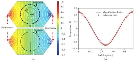
Fig. 6. Simulation results for the thermal magnification device with point thermal sources. a The temperature distribution of the magnification device and reference case. The white lines represent iso-temperature lines. b A quantitative demonstration of equivalence of the temperature on specified boundary.
Numerical simulations for the spheroidal system were also conducted. The parametersandwere respectively 0.35 and 1.1547, as marked out in Fig. 7. In the design,semi-axes of the spheroids were respectivelywhich denoted that the magnifying factor was. It was derived thatby Eq. (11). The spheroidal system was embedded in a square plate sizedSimulation results under uniform external thermal fields and point thermal sources were respectively shown in Figs. 7 and 8. The temperature distributions of the magnification device in Fig. 7 showed good agreement with the corresponding enlarged cases. The quantitative comparisons of temperature values in Fig. 8 verified the correctness of the spheroidal thermal magnification device.
In summary, a magnification device by the method of effective thermal conductivity was proposed. The magnifying conditions for a multilayered system and a coated spheroid object were derived. The magnification device could render an object to be wrongly identified as another one with different size and thermal conductivity, which was verified by numerical results.The design method was simpler than the method of separation of variables, especially for non-spherical objects and devices working under non-uniform thermal fields. It could offer more parameters freedom when using multiple thermal conducting layers. In this work, all parameters were isotropic, homogeneous and with positive values, which were easy to realize. The magnification device worked directly in thermodynamics and could be extended to more physical fields. In this regard, this kind of magnification may enjoy many applications in thermal cases.
Acknowledgements
The work was supported by the National Natural Science Foundation of China (11732002,11672089, 11325210, and 11421091).
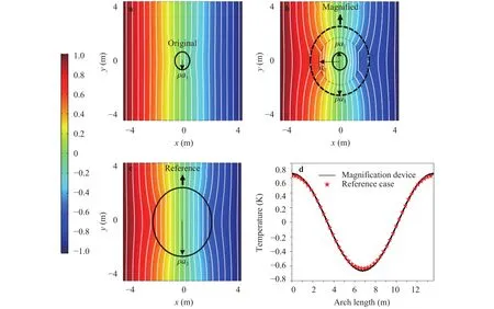
Fig. 7. Simulation results for the spherical system. The white lines represent iso-temperature lines. a The temperature distribution of the original object. b The temperature distribution of the designed magnification device. c The temperature distribution of the reference case. d A quantitative demonstration of equivalence of the temperature on specified boundary.
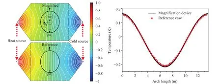
Fig. 8. Simulation results for the spherical system with point thermal sources. a The temperature distribution of the magnification device and reference case. The white lines represent iso-temperature lines. b A quantitative demonstration of equivalence of the temperature on specified boundary.
 Theoretical & Applied Mechanics Letters2018年3期
- Theoretical & Applied Mechanics Letters的其它文章
- Effects of distributed leading-edge roughness on aerodynamic performance of a low-Reynolds-number airfoil: an experimental study
- Triangular temporal-distribution law for disintegrating internal solitons over a step
- A three-dimensional immersed boundary method for non-Newtonian fluids
- Nonlinear thermo-structural behavior of sandwich panels with truss cores under through-thickness gradient temperature field
- Numerical investigation on convective heat transfer over two heated wall-mounted cubes in tandem and staggered arrangement
- Wave reflection in semiconductor nanostructures