A Novel Broadband Microstrip Antenna Based on Operation of Multi-Resonant Modes
2019-07-18 02:00:02TaohuaChenYueyunChenRonglingJianZushenLiuandAlanYang
Computers Materials&Continua 2019年7期
Taohua Chen, Yueyun Chen, , Rongling Jian, Zushen Liu and Alan Yang
Abstract: A novel broadband microstrip antenna under operation of TM1/2,0, TM10 and TM12 modes through a shorting wall and slots is proposed in this paper.Initially, an inverted U-shaped slot is adopted around the feeding point, which achieves a good impedance matching on TM10 mode and separates the patch into two parts.Additionally, a shorting wall is added underneath the edge of smaller patch to excite another onequarter resonant mode, i.e., TM1/2,0 mode of smaller patch close to TM10 mode to expand the impedance bandwidth.Further, the antenna width is enlarged and two symmetrical vertical rectangular slots are cut on the patch to reduce the frequency of TM12 mode to form a broadband.Based on the arrangements above, a wide impedance bandwidth with three minima can finally be achieved.The results show that the impedance bandwidth of proposed antenna for |S11|<-10 dB is extended to 26.5% (23.5-30.67 GHz), which is three times of the conventional antenna at same profile.Moreover, a stable radiation pattern at broadside direction is realized over the operating band.
Keywords: Broadband, microstrip antenna, shorting wall, slots, three resonant modes.
1 Introduction
With the development of modern communication systems, microstrip antenna (MSA) has attracted much attention in wireless communication because of their low profile, small cost, and ease of manufacture [Chen, Jian, Ma et al.(2017)].However, conventional MSA always suffers from a narrow impedance bandwidth, usually less than 3% [Sun, Li, Zhang et al.(2017)].Thus, how to extend the bandwidth of MSA effectively becomes a hot research topic in recent years.
Several methods have been proposed to improve the impedance bandwidth of MSA.The simplest method to expand bandwidth is enhancing the antenna thickness and decreasing the substrate permittivity [Constantine (2005)].However, using thick substrates will enlarge the surface wave leakage leading to a decrease in radiation efficiency and the lowest substrate dielectric constant is 1, i.e., air.
Additionally, in Liao et al.[Liao, Xue and Xu (2012)], the feeding scheme was reconfigured to extend the impedance bandwidth to 115% by introducing another non resonant mode around the fundamental mode.In addition, the L-shaped and F-shaped probe feeds in Mak et al.[Mak, Lai and Luk (2018); Jin and Du (2015)] was adopted to enhance the bandwidth to 54% and 45%, respectively.The reason for bandwidth enhancement of these antennas is that the changed probes can eliminate the impedance inductance to make a great impedance matching.Nevertheless, it is difficult to implement the feeding scheme in a thin substrate.
Moreover, slotting on the patch is another effective method, which was widely used in the past decades to expand the impedance bandwidth because of the simple implementation.The authors in Huynh et al.[Huynh and Lee (1995)] proposed a U-shaped slot on the radiating patch to extend the impedance bandwidth to 47%.When a U-shaped slot was adopted, the frequencies of higher-order modes were reduced to around that of fundamental mode to achieve a broadband [Deshmukh and Ray (2015)].Besides, in Yang et al.[Yang, Zhang, Ye et al.(2001)], a simple E-shaped microstrip patch was proposed.The antenna in Yang et al.[Yang, Zhang, Ye et al.(2001)] could exist two different current paths by two symmetrical vertical rectangular slots cut on the patch, which realized the combination of two resonant modes and enhanced the bandwidth to 30.3%.And in Deshmukh et al.[Deshmukh and Ray (2009)], the antenna bandwidth was extended to 24.6% by adopting a half U-shaped slot on the semi E-shaped antenna.Also, wang-shaped patch in Chung et al.[Chung and Wong (2010)], modified E-shaped patch in Koutinos et al.[Koutinos, Anagnostou, Joshi et al.(2018)] and modified U-slotted antenna in Costanzo et al.[Costanzo and Costanzo (2013)] were proposed for bandwidth enhancement.However, the all antennas with slots loaded on the patch mentioned above are high-profile antennas, which destroys the low-profile property of microstrip antenna.
Furthermore, in recent years, coupling two odd modes of MSA together becomes a new attractive method.The TM10and TM30modes could be combined together to achieve bandwidth enhancement by shorting pins and slots, and the bandwidth was increased to 13%, 18% and 11.8% in Liu et al.[Liu, Zhu and Choi (2017)], Wang et al.[Wang, Ng, Chan et al.(2015)] and Liu et al.[Liu, Zhu, Choi et al.(2017)], respectively.In Liu et al.[Liu, Zhu, Choi et al.(2018); Liu, Zhu and Choi (2017)], through same method to combine TM10and TM12modes, the impedance bandwidth was increased to 10% and 15.3%, respectively.However, since only two odd modes are combined, the impedance bandwidth of these antennas are only twice as wide as that of traditional microstrip antennas, which may hinder the application of these MSAs in broadband communication systems.
In this paper, a novel patch antenna under operation of TM1/2,0, TM10and TM12modes through a shorting wall and slots is proposed to achieve bandwidth expansion.Firstly, an inverted U-shaped slot is loaded around the feeding point on the patch to achieve a good impedance matching and separates the patch into two parts.Secondly, a shorting wall is added underneath the smaller patch produced by the inverted U-shaped slot, which will excite another resonant mode, i.e., TM1/2,0of smaller patch antenna close to TM10mode to expand the impedance bandwidth.Thirdly, to further extend the bandwidth, the antenna width is enlarged and two symmetrical vertical rectangular slots is cut on the patch to reduce the frequency of TM12mode to form a broadband.Finally, a broadband of 26.5% (23.5-30.67 GHz) for |S11| < -10 dB is achieved and the impedance bandwidth is three times that of conventional antenna at same profile.Moreover, a stable radiation pattern at the broadside direction is realized over the operating band.In this paper, fullwave simulation software HFSS 13.0 is used for simulation calculation.
2 Antenna configuration and design process
2.1 Antenna configuration
The configuration of the proposed broadband microstrip antenna is shown in Fig.1.It consists of a rectangular radiating patch with the size of L×W, a ground plane with the size of Ls×Ws, an inverted U-shape slot with the width of W2, two symmetrical vertical rectangular slots with the size of L×W1and a shorting wall with the dimensions of W3×H which is L3distance from the lower edge of patch.Between the patch and the ground, a dielectric substrate RO5880 with a permittivity of εr=2.2 and a thickness of H=0.787 mm is selected in this paper for antenna design.And all parameters for the proposed broadband antenna in Fig.1 are tabulated in Tab.1.
Firstly, the inverted U-shaped slot is adopted to achieve impedance matching of the traditional antenna and separates the patch into two parts.Secondly, a shorting wall is added to connect the smaller patch and ground to excite a one-quarter wavelength resonant mode, i.e., TM1/2,0of the smaller patch to expand the impedance bandwidth.To further extend the bandwidth, the antenna width is enlarged and two symmetrical vertical rectangular slots are cut on the patch to reduce the frequency of TM12mode.Finally, a wideband antenna can be realized with three minima in operating band.
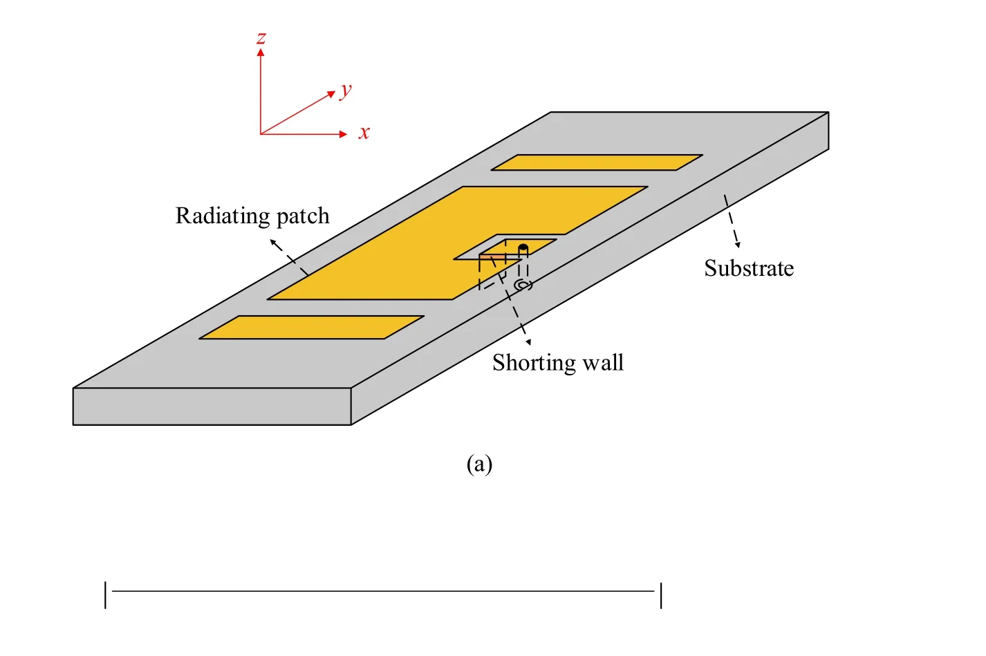
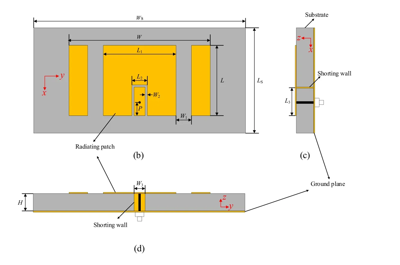
Figure 1: Configuration of the proposed broadband antenna loaded with a shorting wall and slots (a) 3D view.(b) Top view.(c) Right view.(d) Front view

Table 1: Dimensions of the proposed broadband antenna in Fig.1 (mm)
2.2 Design process
In order to expand the impedance bandwidth of microstrip antenna, the structure of traditional microstrip antenna is modified.The design process of proposed broadband antenna is shown in Fig.2.
Initially, the ANT 1 is an inverted U-shaped slot cut around the feeding point on the radiating patch of the conventional antenna to achieve impedance matching.Then, for the ANT 2, another resonant mode near TM10mode is excited through a shorting wall added underneath the edge of smaller patch produced by the inverted U-shaped slot.To further expand the impedance bandwidth, for the ANT 3, i.e., proposed antenna, the antenna width is enlarged and two symmetrical vertical rectangular slots are cut on the patch to reduce the frequency of TM12mode close to that of TM10mode.The radiating patches of ANT 1 and ANT 2 are with the same size (W=1.5 L), and the patch width of ANT 3 is enlarged to twice of the length.The simulated reflection coefficients are shown in Fig.3.The antennas dimensions are optimized to good impedance matching.It can be observed from the Fig.3 that the impedance bandwidth for |S11|<-10 dB of ANT 1 is 9.4% (24.17-26.55 GHz), and is 18.4% (23.45-28.2 GHz) for ANT 2.The reason of enhancement of the impedance bandwidth is that another resonant mode, i.e., TM1/2,0mode which is excited through a shorting wall underneath the smaller patch produced by the inverted Ushaped slot is coupled to the fundamental TM10mode.As for the proposed antenna ANT 3, the impedance bandwidth is further extended to 26.5% (23.5-30.67 GHz).Through two symmetrical vertical rectangular slots and increasing the patch width to twice of the length, for ANT 3, another resonant mode, i.e., TM12mode is added to form a wider bandwidth, which can be easily observed from Fig.3.
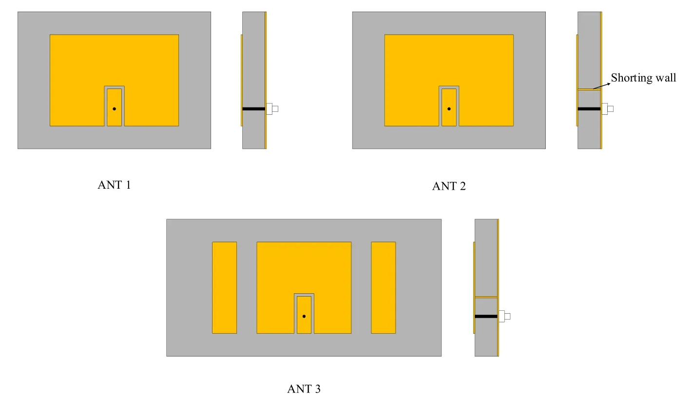
Figure 2: Design process of proposed antenna
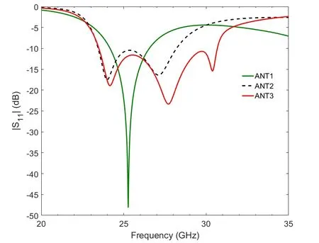
Figure 3: Simulated reflection coefficients of three antennas
2.3 Operating mechanism
To understand the operating mechanism of the proposed antenna, Fig.4 plots the electric field distributions of the radiating patch.For the electric field distributions at 24.18 GHz, the electric field is mainly distributed at lower edge of the smaller patch around the feeding point, which is similar to the one-quarter wavelength resonant mode, i.e., TM1/2,0mode of smaller patch.While at the 27.74 GHz, the electric field distributions are similar to the fundamental TM10mode which is mainly distributed at the edge of conventional patch.In addition, for the 30.39 GHz, the electric field is mainly distributed at the patches on left and right sides produced by two symmetrical vertical rectangular slots.Compared with the electric field distributions of TM12mode in the patch without rectangular slots, the rectangular slots destroy the electric field distributions, which will reduce the frequency of TM12mode.Though coupling the three resonant modes together, a broadband microstrip antenna can be realized.
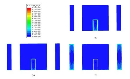
Figure 4: Simulated electric field distributions of proposed antenna.(a) 24.18 GHz.(b) 27.74 GHz.(c) 30.39 GHz
2.4 Reducing the resonant frequency of TM12 mode
In order to better illustrate how to reduce the frequency of TM12mode, the specific analysis is made in this subsection.According to the cavity model [Garg, Bhartia, Bahl et al.(2001)], the resonant frequencies (fmn) of TMmnmodes in microstrip antenna can be expressed as follows:

where c is the light speed in the free space, εris the dielectric constant of substrate, and m=1, 2, 3 … and n=1, 2, 3 …
Based on formula (1), the patch width (W) plays an important role in the frequency of TM12mode (f12), yet has no effect on that of TM10mode (f10).Therefore, when W is increased, f12will be reduced while f10keeps constant.In this paper, considering the antenna size, the patch width is enlarged to twice of the length.However, when patch width is twice of length, the distance of f10and f12is still large, which cannot to form a wide bandwidth.Thus, two symmetrical vertical rectangular slots are cut on the patch to further reduce f12.
Initially, four symmetrical vertical rectangular slots are loaded on the patch, which can be observed at Fig.5.
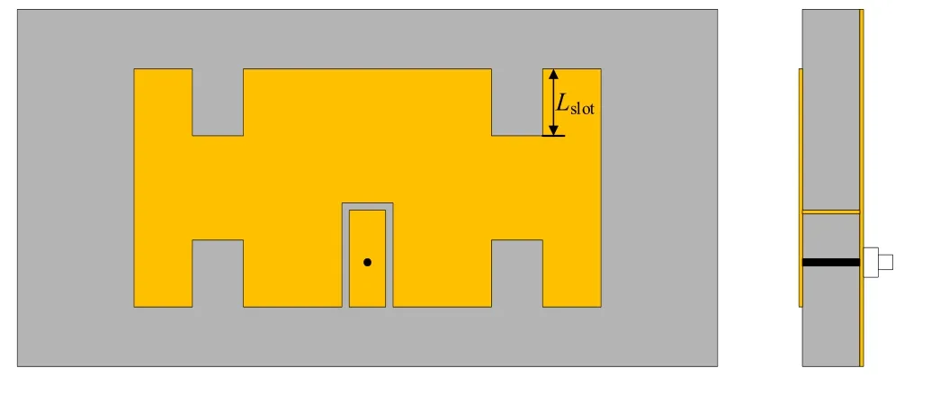
Figure 5: Antenna with four symmetrical vertical rectangular slots
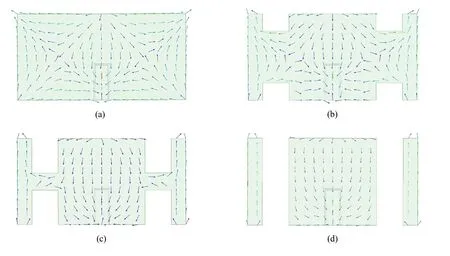
Figure 6: Current distribution of TM12 mode at different slots length.(a) Without slots, 39.57 GHz.(b) Lslot=0.2L, 36.17 GHz.(c) Lslot=0.4L, 31.27 GHz.(d) Lslot=0.5L, 30.26 GHz
Because the four vertical rectangular slots are parallel to current flow direction of TM10mode, they have little effect on f10.However, for the TM12mode, the slots enlarge the horizontal current path, which will reduce the f12.To better understand the effects of four symmetrical vertical rectangular slots on TM12mode, the current distribution of TM12mode at different slots length is plotted on Fig.6, and the other antenna parameters are fixed as shown in Tab.1.
It can be clearly seen from Fig.6 that the slots length has great effect on the TM12current path corresponding to f12.Moreover, Fig.6 also gives the f12at different slots length, we can find that the f12decreases from 39.57 GHz to 30.26 GHz as the slots length increases from 0 to 0.5L.Moreover, to better show the effect of slots length on f10and f12, Fig.7 plots the f10and f12varying with the slots length when other parameters are fixed.As can be observed from Fig.7, the f10keeps stable while f12decreases as the slots length increases, as predicted above.
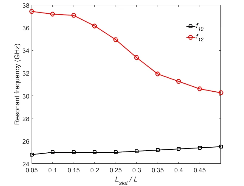
Figure 7: f10 and f12 varying with the slots length Lslot
Finally, considering the all antenna performances, we select Lslot= 0.5L in this paper and for this reason there are only two large symmetrical vertical rectangular slots at last.Note that the TM02mode between TM10and TM12modes is removed when Lslot= 0.5L is adopted, and the radiation peak of TM12mode is changed to boresight because of the slots [Xiao, Wang, Shao et al.(2005)].
3 Parametric studies
To deeply understand how the influence of dimensional parameters on the proposed antenna performances and design flow, parametric studies for the proposed wideband antenna is carried out by using HFSS 13.0.In this paper, several key parameters listed in Tab.1 are extensively studied under other parameters to be fixed.
3.1 Effects of two symmetrical vertical rectangular slots position L1 and width W1
Fig.8 plots the simulated results of the |S11| as a function of frequency at different symmetrical vertical rectangular slots position L1.As can be observed from the Fig.8, compared with the third resonant mode, i.e., TM12mode, the first resonant mode (TM1/2,0mode) and second resonant mode (TM10mode) are less influenced by the vertical rectangular slots position L1.The reason is that two symmetrical vertical rectangular slots cut off the horizontal current of TM12mode, while have little effect on the vertical current of TM1/2,0and TM10modes.When L1is from 3.1 mm to 3.5 mm, the impedance matching of TM12mode becomes better gradually and the frequency of TM12mode increases.Yet, when L1=3.5 mm, the band between TM10and TM12mode becomes mismatched, and the best bandwidth can be obtained at L1=3.3 mm from Fig.8.
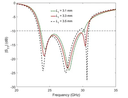
Figure 8: |S11| as a function of frequency at different L1
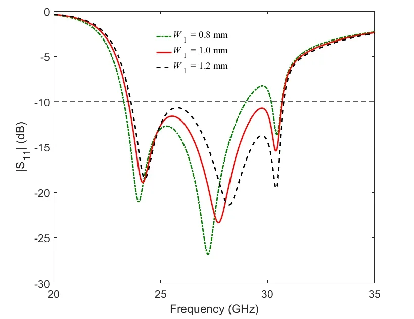
Figure 9: |S11| as a function of frequency at different W1
In Fig.9, the |S11| as a function of frequency at different vertical rectangular slots width W1is illustrated.Like L1, the W1has little effect on the TM1/2,0mode.However, the W1begins to affect TM10and TM12modes concurrently.The wider the W1, the closer the distance between TM10and TM12modes.And the widest bandwidth can be seen at W1=1.0 mm from Fig.9.
3.2 Effects of smaller patch length L3 and width W3
Fig.10 gives the |S11| as a function of frequency at different smaller patch length L3.As expected, the L3has a great impact on the TM1/2,0mode.When L3increases from 1.2 mm to 1.4 mm, the frequency of TM1/2,0corresponding to the L3decreases.Meanwhile, the L3affects the impedance matching of all three modes.And the best value of L3can be found from Fig.10 is L3=1.3 mm.
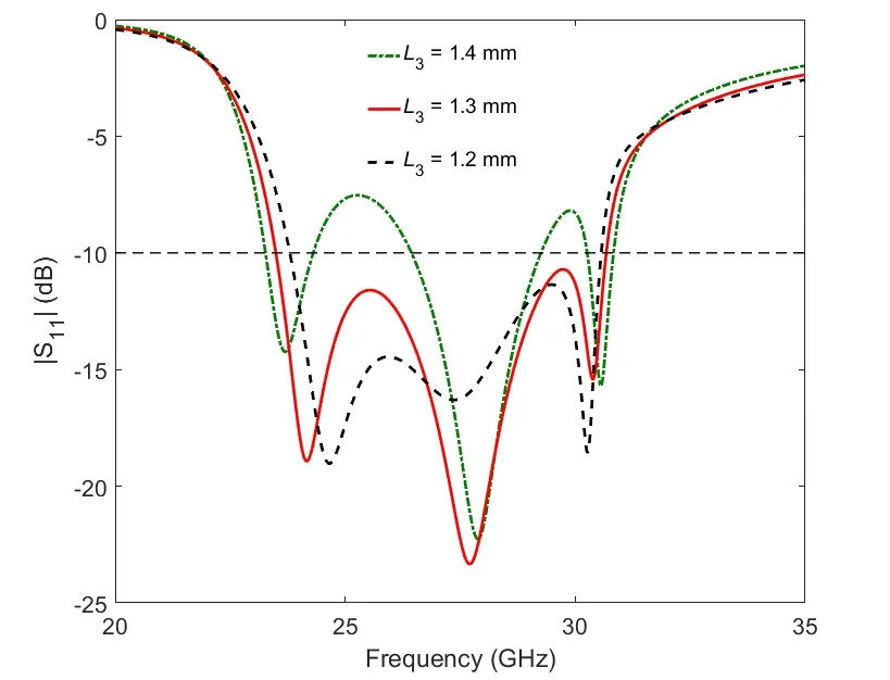
Figure 10: |S11| as a function of frequency at different L3
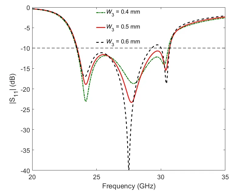
Figure 11: |S11| as a function of frequency at different W3
Fig.11 shows the |S11| as a function of frequency at different smaller patch width W3.The W3mainly affects the impedance matching of three resonant modes and has little influence on the resonant frequencies of three modes.Considering the whole |S11| performance in Fig.11, the W3=0.5 mm is selected in this paper.
3.3 Effects of inverted U-shaped slot width W2 and feeding position P
Fig.12 and Fig.13 plot the |S11| as a function of frequency at different inverted U-shaped slot width W2and feeding position P, respectively.
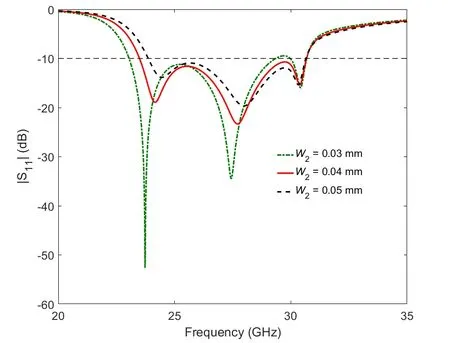
Figure 12: |S11| as a function of frequency at different W2
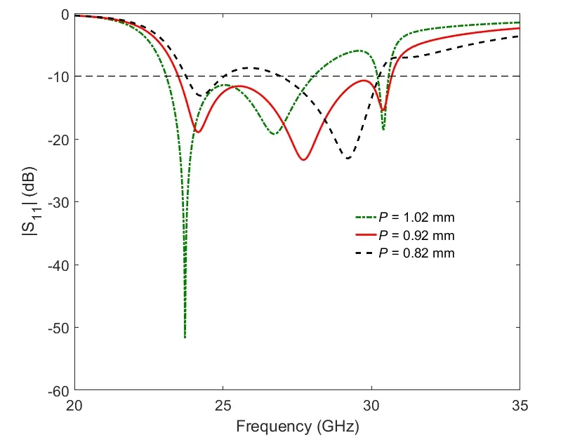
Figure 13: |S11| as a function of frequency at different P
As can be observed from Fig.12, the W2mainly influences the impedance matching of TM1/2,0and TM10modes.And best |S11| performance of TM1/2,0and TM10modes is achieved at W2=0.03 mm.However, the band between TM10and TM12mode is mismatched at W2=0.03 mm.Thus, considering the whole |S11| performance, in this paper, W2=0.04 mm is selected.For the feeding position P, as can be seen from Fig.13, it has great effects on the matching condition.Moreover, the best value of P is realized at P=0.92 mm.
4 Results and discussion
The reflection coefficient of proposed broadband microstrip antenna is plotted in Fig.14.
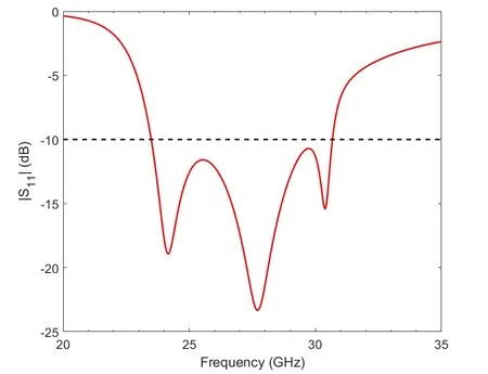
Figure 14: |S11| of proposed broadband antenna
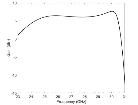
Figure 15: Gain at broadside direction of proposed antenna
It can be observed from Fig.14 that the impedance bandwidth for |S11|<-10 dB is extended to 26.5%, ranging from 23.5 to 30.67 GHz.Meanwhile, there are three minima in the operating band, which is consistent with the three resonant modes mentioned above.Compared with the conventional antenna bandwidth of 9.4% at the same profile, the impedance bandwidth of proposed antenna is about three times that of the conventional antenna through coupling three resonant modes together.
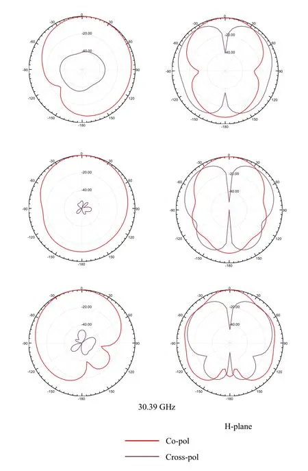
Figure 16: Normalized radiation patterns of proposed antenna at 24.18, 27.74 and 30.39 GHz
Moreover, the gain as a function of frequency at broadside direction of proposed antenna is illustrated in Fig.15.It can be seen from Fig.15 that the proposed antenna has obtained a stable gain of around 6 dBi at the broadside direction in the operating band, which shows that the proposed wideband antenna has a good gain performance in the operating band.
Fig.16 gives the normalized radiation patterns of proposed antenna at three minima of 24.18, 27.74 and 30.39 GHz.As for the E-plane, the co-polarization radiation patterns are a little asymmetric because of the asymmetric antenna structure.Yet, it is still stable at the operating band.Meanwhile, the cross-polarization level in E-plane is lower than -30 dB over the operating band, which indicates that the proposed broadband antenna has a good radiation performance in E-plane.While for the H-plane, the co-polarization radiation patterns are symmetric, and the cross-polarization level in the broadside direction is lower than -40 dB over the operating band.
5 Conclusion
In this paper, a novel broadband microstrip antenna is proposed and analyzed.A shorting wall is adopted to excite a one-quarter resonant mode (TM1/2,0mode) close to the fundamental mode (TM10mode) to expand the impedance bandwidth.Further, through two symmetrical vertical rectangular slots and enlarging the antenna width to twice of the length, the TM12mode is also adjusted in proximity to the TM10mode.Finally, a broadband microstrip antenna with impedance bandwidth of 26.5% for |S11|<-10 dB is achieved, and its bandwidth is about three times of the conventional antenna at same profile.In addition, a stable radiation pattern at the broadside direction is realized over the operating band.The proposed antenna is compact and wideband, it can be used for 5G wireless communication in the future.
Acknowledgement:This work was supported by National Science and Technology Major Project No.2017ZX03001021-005.
References
Chen, Y.Y.; Jian, R.L.; Ma, S.S.; Mohadeskasaei, S.A.(2017): A research for millimeter wave patch antenna and array synthesis.IEEE Wireless and Optical Communication Conference, pp.1-5.
Chung, K.L.; Wong, C.H.(2010): Wang-shaped patch antenna for wireless communications.IEEE Antennas & Wireless Propagation Letters, vol.9, no.1, pp.638-640.
Constantine, A.B.(2005): Antenna Theory: Analysis and Design.John Wiley & Sons, USA.Costanzo, S.; Costanzo, A.(2013): Compact U-slotted antenna for broadband radar applications.Journal of Electrical and Computer Engineering,vol.2013, pp.10.
Deshmukh, A.A.; Ray, K.P.(2009): Compact broadband slotted rectangular microstrip antenna.IEEE Antennas & Wireless Propagation Letters, vol.8, no.4, pp.1410-1413.
Deshmukh, A.; Ray, K.P.(2015): Analysis of broadband variations of U-slot cut rectangular microstrip antennas.IEEE Antennas and Propagation Magazine, vol.57, no.2, pp.181-193.
Garg, R.; Bhartia, P.; Bahl, I.; Ittipiboon, A.(2001): Microstrip Antenna Design Handbook.Artech House, UK.
Huynh, T.; Lee, K.F.(1995): Single-layer single-patch wideband microstrip antenna.Electronics Letters, vol.31, no.16, pp.1310-1312.
Jin, Y.; Du, Z.(2015): Broadband dual-polarized F-probe fed stacked patch antenna for base stations.IEEE Antennas & Wireless Propagation Letters, vol.14, pp.1121-1124.
Koutinos, A.G.; Anagnostou, D.E.; Joshi, R.; Podilchak, S.K.; Kyriacou, G.A.et al.(2018): Modified easy to fabricate E-shaped compact patch antenna with wideband and multiband functionality.IET Microwaves, Antennas & Propagation, vol.12, no.3, pp.326-331.
Liao, S.W.; Xue, Q.; Xu, J.H.(2012): Parallel-plate transmission line and L-plate feeding differentially driven H-slot patch antenna.IEEE Antennas & Wireless Propagation Letters, vol.11, no.8, pp.640-644.
Liu, N.W.; Zhu, L.; Choi, W.W.(2017): A differential-fed microstrip patch antenna with bandwidth enhancement under operation of TM10and TM30modes.IEEE Transactions on Antennas and Propagation, vol.65, no.4, pp.1607-1614.
Liu, N.W.; Zhu, L.; Choi, W.W.(2017): A low-profile wide-bandwidth planar inverted-F antenna under dual resonances: principle and design approach.IEEE Transactions on Antennas and Propagation, vol.65, no.10, pp.5019-5025.
Liu, N.W.; Zhu, L.; Choi, W.W.; Zhang, X.(2017): Wideband shorted patch antenna under radiation of dual resonant modes.IEEE Transactions on Antennas and Propagation, vol.65, no.6, pp.2789-2796.
Liu, N.W.; Zhu, L.; Choi, W.W.; Zhang, X.(2018): A low-profile differential-fed patch antenna with bandwidth enhancement and sidelobe reduction under operation of TM10and TM12modes.IEEE Transactions on Antennas and Propagation, vol.66, no.9, pp.4854-4859.
Mak, K.M.; Lai, H.W.; Luk, K.M.(2018): A 5G wideband patch antenna with antisymmetric L-shaped probe feeds.IEEE Transactions on Antennas and Propagation, vol.66, no.2, pp.1-1.
Sun, W.; Li, Y.; Zhang, Z.; Feng, Z.(2017): Broadband and low-profile microstrip antenna using strip-slot hybrid structure.IEEE Antennas and Wireless Propagation Letters, vol.16, no.99, pp.3118-3121.
Wang, D.; Ng, K.B.; Chan, C.H.; Wong, H.(2015): A novel wideband differentiallyfed higher-order mode millimeter-wave patch antenna.IEEE Transactions on Antennas and Propagation, vol.63, no.2, pp.466-473.
Xiao, S.Q.; Wang, B.Z.; Shao, W.; Zhang, Y.(2005): Bandwidth-enhancing ultralowprofile compact patch antenna.IEEE Transactions on Antennas and Propagation, vol.53, no.11, pp.3443-3447.
Yang, F.; Zhang, X.X.; Ye, X.; Rahmat-Samii, Y.(2001): Wide-band E-shaped patch antennas for wireless communications.IEEE Transactions on Antennas and Propagation, vol.49, no.7, pp.1094-1100.
 Computers Materials&Continua2019年7期
- Computers Materials&Continua的其它文章
- A Cross-Tenant RBAC Model for Collaborative Cloud Services
- Outage Capacity Analysis for Cognitive Non-Orthogonal Multiple Access Downlink Transmissions Systems in the Presence of Channel Estimation Error
- Knowledge Composition and Its Influence on New Product Development Performance in the Big Data Environment
- Fuzzy Search for Multiple Chinese Keywords in Cloud Environment
- Network Embedding-Based Anomalous Density Searching for Multi-Group Collaborative Fraudsters Detection in Social Media
- A New NTRU-Type Public-Key Cryptosystem over the Binary Field