Magnet stage optimization of 5 kW multicusped field thruster
2020-09-14 01:13:44PengHU胡鵬DarenYU于達仁andYanSHEN沈巖
Plasma Science and Technology 2020年9期
Peng HU (胡鵬),Daren YU (于達仁) and Yan SHEN (沈巖),5,6
1 Beijing Institute of Control Engineering,Beijing 100094,People’s Republic of China
2 Lab of Advanced Space Propulsion,Beijing 100094,People’s Republic of China
3 Beijing Engineering Research Center of Efficient and Green Aerospace Propulsion Technology,Beijing 100094,People’s Republic of China
4 Plasma Propulsion Laboratory of Harbin Institute of Technology,Harbin 150001,People’s Republic of China
5 School of Aeronautics and Astronautics,Sun Yat-sen University,Guangzhou 510006,People’s Republic of China
6 Author to whom any correspondence should be addressed.
Abstract
Keywords:multi-cusped field,magnet number,magnet length,performance optimization
1.Introduction
The multi-cusped field thruster is a unique electric propulsion device.It is inspired by the multi-cusped field in a travelingwave tube.Kornfeld et al used this special magnetic field in the design of a new concept electric thruster,and it was firstly named as the high efficiency multi-stage plasma thruster(HEMPT) [1-4].The thruster employs several permanent magnet rings to form a unique multi-cusped field [5-8].The plasmas could be well confined by the magnetic field in a cylindrical discharge channel,and the plasma erosion rates on the channel wall could be dramatically reduced.As a result,the thruster shows a significant long-lifetime performance advantage [9-11].
A simple physical process of a multi-cusped field thruster is shown in figure 1.The discharge channel is generally cylindrical and made of boron nitride.A series of permanent magnets with opposite polarities are coaxially mounted along the axis and a multi-cusped field configuration is formed[12,13].An anode and a gas supply structure are located at the upstream of the discharge channel,and a hollow cathode is installed in the plume region.After the thruster is ignited,some electrons emitted by the hollow cathode neutralize the ions in the downstream plume region,and the other electrons move upstream toward the anode [4,10,12,14,15].These electrons are strongly confined by the multi-cusped field in the discharge channel,and the high-speed electrons move back and forth between the adjacent magnetic cusps under the effects of electric field force and magnetic mirror force.During this process,some xenon(Xe)atoms in the discharge channel are ionized with electron-neutral collisions [4,16].Then,a cross-field electron current in the cusped magnetic field can be formed with classical or abnormal conduction mechanisms [17,18].Meanwhile,the ions generated in the discharge channel are accelerated by the electric field near the channel exit,and a reaction thrust is formed [4,12].
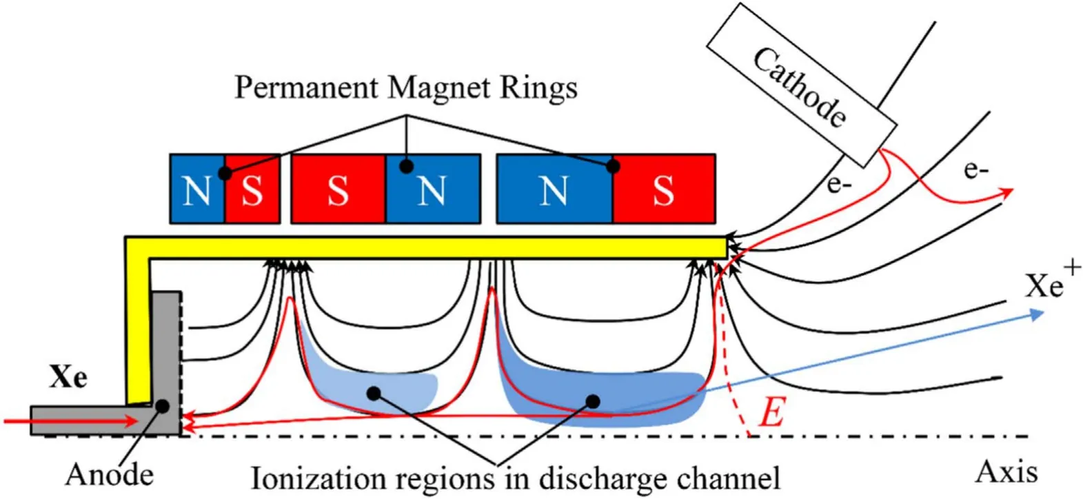
Figure 1.Schematic of the multi-cusped field thruster.

Figure 2.Structure of CFPT-60.(a) Picture,and (b) magnetic field structure.
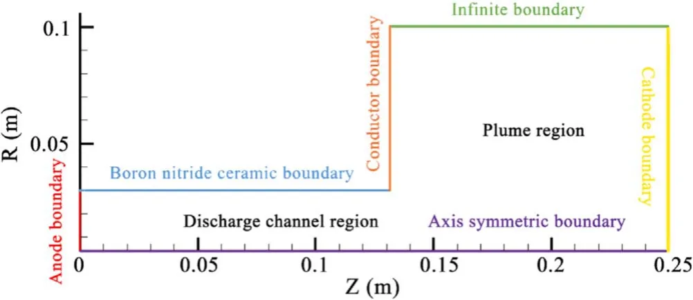
Figure 3.Simulation regions and boundary conditions.
The results of previous studies have shown that the distributions of ionization regions are determined by the back and forth electron moments in the discharge channel,and the acceleration region is established through the electron transports near the channel exit [19,20].Therefore,the basic ionization and acceleration processes are attributed to the electron motion behaviors,which are directly related to the magnetic field characteristics [7].In 2014,research at the Harbin Institute of Technology revealed the internal relationships between the magnetic field and electric field through particle-in-cell (PIC) numerical simulation [17].In 2015,experimental studies validated that the magnetic field is a decisive factor in the establishment of the ionization regions[21,22].Both the magnet number and magnet stage length are two key magnetic field design parameters,which affect the motion behaviors of the electrons directly,and they have important effects on the thruster performances.In this paper,these two parameters are studied for the optimization of a 5 kW multi-cusped plasma field thruster (CFPT-60) by the PIC method.
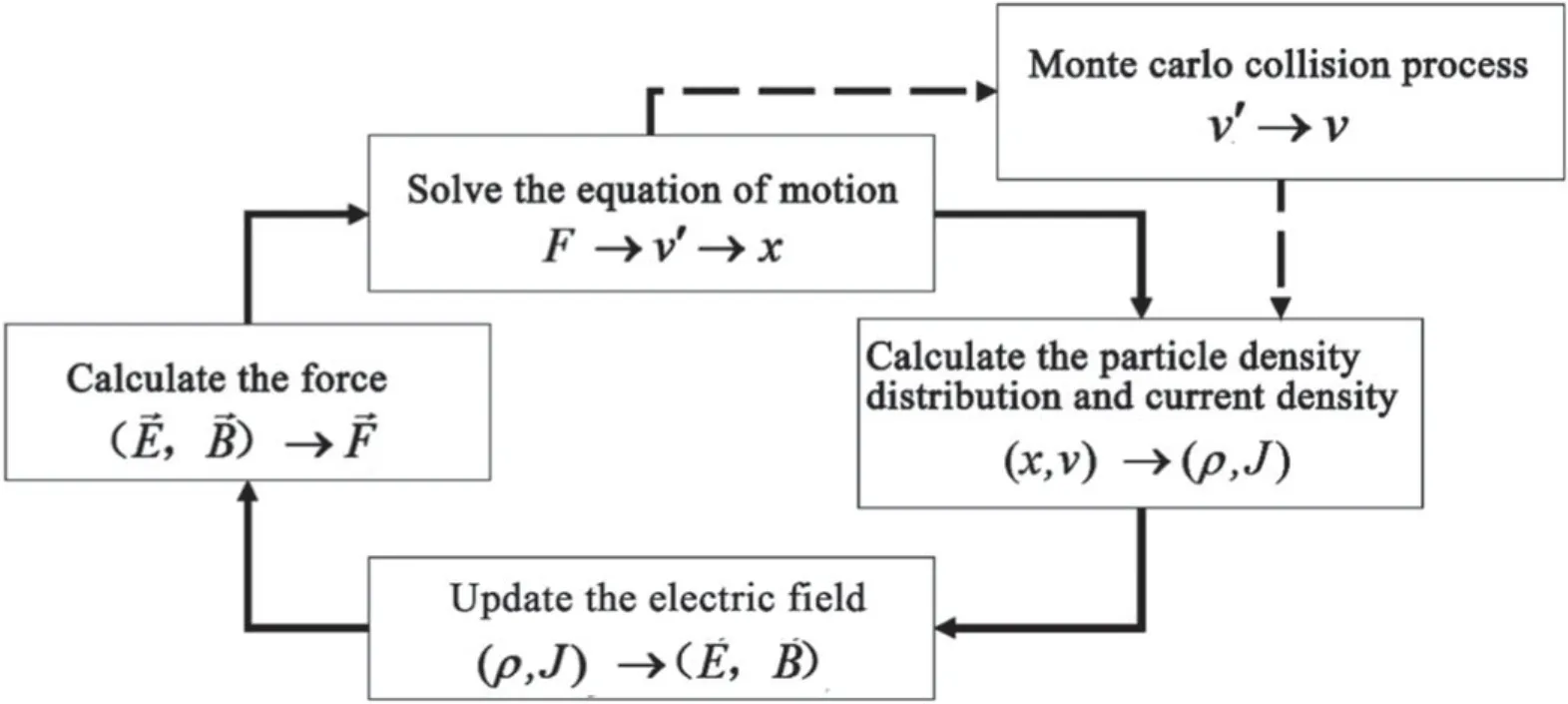
Figure 4.Algorithm flow of the PIC model.
2.Numerical simulations of CFPT-60
2.1.Introduction of CFPT-60
Since 2017,researchers in the Lab of Advanced Space Propulsion of Beijing Institute of Control Engineering have been developing a 5 kW class multi-cusped field plasma thruster (CFPT-60) for the application of high-orbit satellites [20].The thruster has a cylindrical boron nitride discharge channel with an inner diameter of 60 mm.In order to reduce the channel erosion,the discharge channel near the exit plane uses a divergent channel structure,as shown in figure 2.The thruster is equipped with a thermal screen to improve the thermal radiation ability and to decrease the thruster operating temperature.The Xe gas is used as thruster propellant and the atoms can enter the discharge channel uniformly after passing through the anode gas distributor.The permanent magnet stages are coaxially mounted along the axis,as shown in figure 2(b).The thruster shell is made of aluminum,which is used to fix permanent magnet stages at the required positions.
2.2.PIC numerical model
Numerical simulation methods have been widely used in many typical Hall effect thrusters (HETs) [23,24]and thrusters with anode layer (TALs) [25],as well as in other electric propulsion devices,including cylinder Hall thrusters [26],ion thrusters [27],arc thrusters [28],and hollow cathodes [29-31].In this paper,a particle-in-cell plus Monte Carlo (PIC-MCC) model is established on the basic structure of CFPT-60.In this model,two-dimensional space(radial and axial) and three-dimensional velocity components (2 D-3 V) are simulated.The maximum magnetic field strength in this model is about 0.3 T,which is approximately 10 times stronger than the typical value of Hall thrusters.In Hall thrusters,the impedance for electrons results from the radial magnetic field.In addition,in the multi-cusped field thruster,it also has the impedance effects from the multi-magnetic cusps.
The simulation regions and boundary conditions are shown in figure 3.The simulation model contains a discharge channel region and a plume region,and its simulation region has a maximum axial length of 0.25 m and a radial length of 0.1 m.The left model boundary in the discharge channel is the anode boundary,and in this boundary,the potential is fixed at the anode voltage and the electrons are removed.The upper boundary in the discharge channel region is the boron nitride ceramic boundary and the lower boundary is the axis symmetric boundary.When the electrons move to the axis symmetric boundary,they are elastically reflected to the simulation region.The left boundary of the plume region is the conductor boundary,which represents the thruster magnet mounting plate.The right boundary of the plume region is the cathode boundary,and its potential is set at 0 V.The electrons are ejected in the simulation region by the cathode with a 2 eV average initial temperature and they meet with a half Maxwell distribution.The upper boundary in the plume region is the infinite boundary,and the electrons are removed at this boundary [17,29].
The algorithm flow of the PIC model is shown in figure 4.At the beginning of each simulation cycle,the model uses the magnetic field and electric field from the previous cycle,and the force F of the particle can be calculated.The magnetic field is imported by the simulation of two-dimensional FEMM software.The particle velocities and positions are updated by the particle movement equation,which is solved by the Boris leapfrog method.
The direct simulation Monte Carlo (DSMC) method is adopted to solve the collision process of atoms.The single ionization,elastic scattering,and excitation between atoms and electrons are simulated with the MCC method.The ion-neutral Coulomb collisions and three-body and radiative re-combinations are neglected due to their small collision probabilities.This model is self-consistent except for the anomalous cross-field electron diffusion,and the Bohm coefficient of 1/64 is used in this model.
At the end of each electron loop,ions are generated at the collision positions,and the initial ion velocity is equal to the local neutral background velocity.The Poisson equation is solved by the dynamic alternating direct implicit method,and then the electric field could be updated.Both the time step and space step satisfy the following inequalities:
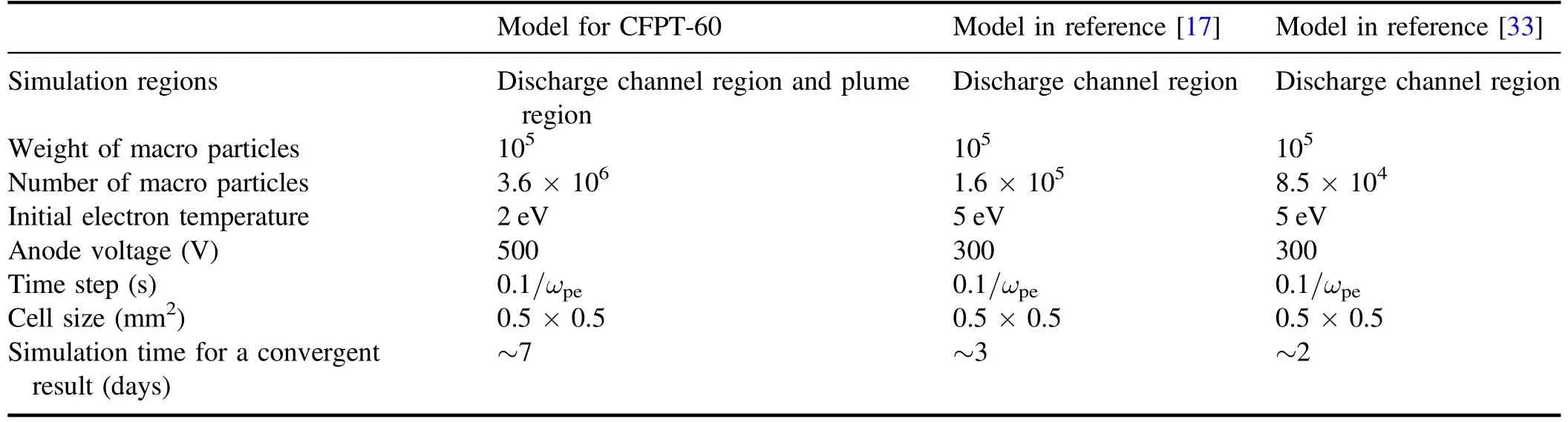
Table 1.Comparisons of the parameters in different simulation models.
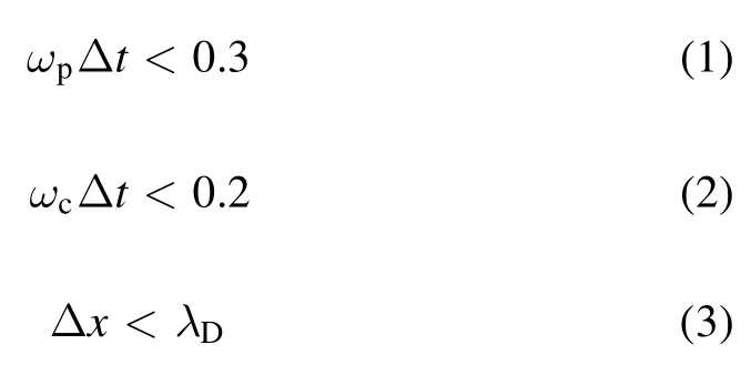
In these inequalities,ωpis the plasma oscillation frequency,ωcis the electron cyclotron frequency,andλDis the Debye length.In the simulation model,Δt=0.1ωp-1and Δx=0.5 mm.Other constants in the model are consistent with the previous works [32].A steady-state PIC model could be gradually established through the iterative processes.The numbers of macro particles in the model are increased and a convergence state can be formed.The simulations are calculated by using a personal computer.After about 7 days of calculation,the convergent results could be obtained successfully.Detailed parameter comparisons of different simulation models are shown in table 1.
3.Simulation results and discussions
3.1.Optimization of magnet stage number
According to the previous experimental results,the distributions of ionization regions in a multi-cusped field thruster have strict corresponding relationships with the number and the length of magnet stages [19].The numberof ionization regions is determined by the number of magnet stages,but the distributions of ionizations at each stage are dramatically different with the change of electron input boundaries[20].In this study,a two-stage thruster and a three-stage thruster are simulated separately by the PIC models,as shown in table 2.The length of the third stage is changed and the lengths of the first and second stages remain the same.
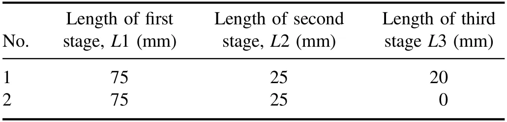
Table 2.The magnetic fields with different magnet lengths.
As shown in figure 5,the potential distributions in these two magnetic fields are highly similar:the dominant acceleration regions are located at the outlet plane.These results mean that changing the magnet number has an insignificant impact on the electric field.
It can be seen in figure 6 that the distributions of the electron number density and the ion number density are nearly the same,which satisfies the basic physical characteristics of the plasma quasi-neutrality.The plasmas in the thruster are concentrated near the axis due to the inherent magnetic confinement characteristics:the threestage magnetic field thruster has two ionization regions while the two-stage magnetic field thruster has only one ionization region.
It can be seen in figure 7 that the distributions of ionization rate are changed in cases with different magnet number.In the three-stage magnetic field,the ionization region in Z=0.02-0.06 m has a relatively uniform distribution in the radial direction.Due to the weak confinement in the two-stage magnetic field,the electron leakage along the axis is increased [17],and the ionization rate is not evenly distributed along the radial direction.Therefore,the three-stage magnetic field shows a higher ionization rate.
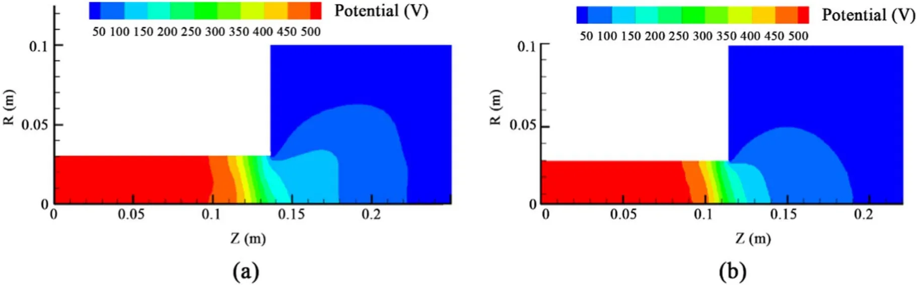
Figure 5.The potential distributions.(a) Three-stage magnetic field,and (b) two-stage magnetic field.
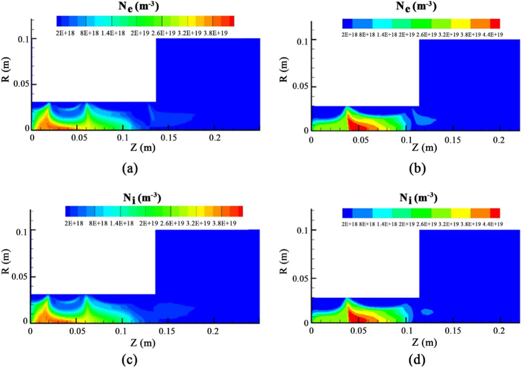
Figure 6.The plasma density distributions.(a)Electron number density in the three-stage magnetic field,(b)electron number density in the two-stage magnetic field,(c)ion number density distribution in the three-stage magnetic field,and(d)ion number density distribution in the two-stage magnetic field.
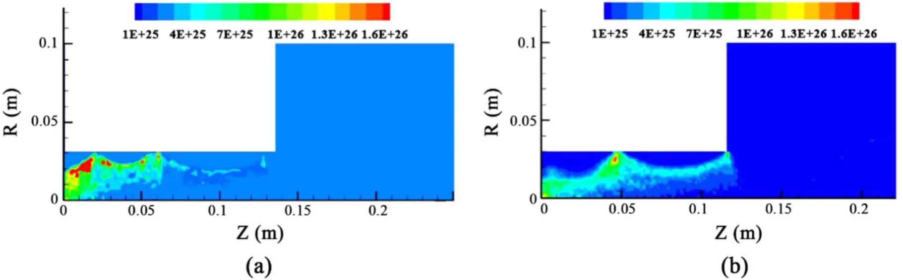
Figure 7.The ionization rate distributions.(a) Three-stage magnetic field,and (b) two-stage magnetic field.

Figure 8.The electron temperature.(a) Three-stage magnetic field,and (b) two-stage magnetic field.
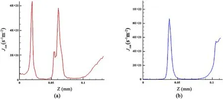
Figure 9.The ion flux density at the channel wall.(a) Three-stage magnetic field,and (b) two-stage magnetic field.
It can be seen in figure 8 that the high-energy electrons in the two magnetic field configurations are concentrated near the axis close to the exit,and the high-energy electrons in the three-stage magnetic field are more widely distributed in the axial direction than those in the two-stage magnetic field.The differences in electron temperature distributions should be attributed to the energy loss processes.The threestage magnetic field has a higher electron confinement efficiency,low energy loss,and wide distribution range of high-energy electrons,while in the two-stage magnetic field,the electron confinement efficiency is lower,and it has more energy loss and a narrower distribution range of highenergy electrons.The differences of electron confinement abilities are attributed to the higher magnetic field strength and higher magnetic mirror ratio of the three-stage magnetic field.A higher magnetic mirror ratio will eventually reduce the plasma corrosion rate on the channel wall.As we can see in figure 9,the ion flux density on the wall surface in the three-stage magnetic field thruster is about 6.5×10²¹s?1m?2,while it is about 9×10²¹s?1m?2in the twostage magnetic field.Therefore,the plasma erosion on the channel wall in the three-stage magnetic field is nearly 27.8% lower than the two-stage magnetic field.
3.2.Optimization of magnet length
Compared with the two-stage magnetic field,the three-stage magnetic field has a higher electron confinement efficiency,lower ion energy loss,wider distribution of high-energy electrons,and higher ionization rate.Therefore,the threestage magnetic field has a superior configuration.In this part,several three-stage magnetic fields with different magnet lengths are simulated.As we have validated in the previous experiments,the magnet length of the first stage has the most significant effect on the thruster performance[34].So the length optimization of this stage is simulated in this paper,as shown in table 3.Five cases with different magnet lengths from 68 mm to 88 mm are simulated separately.
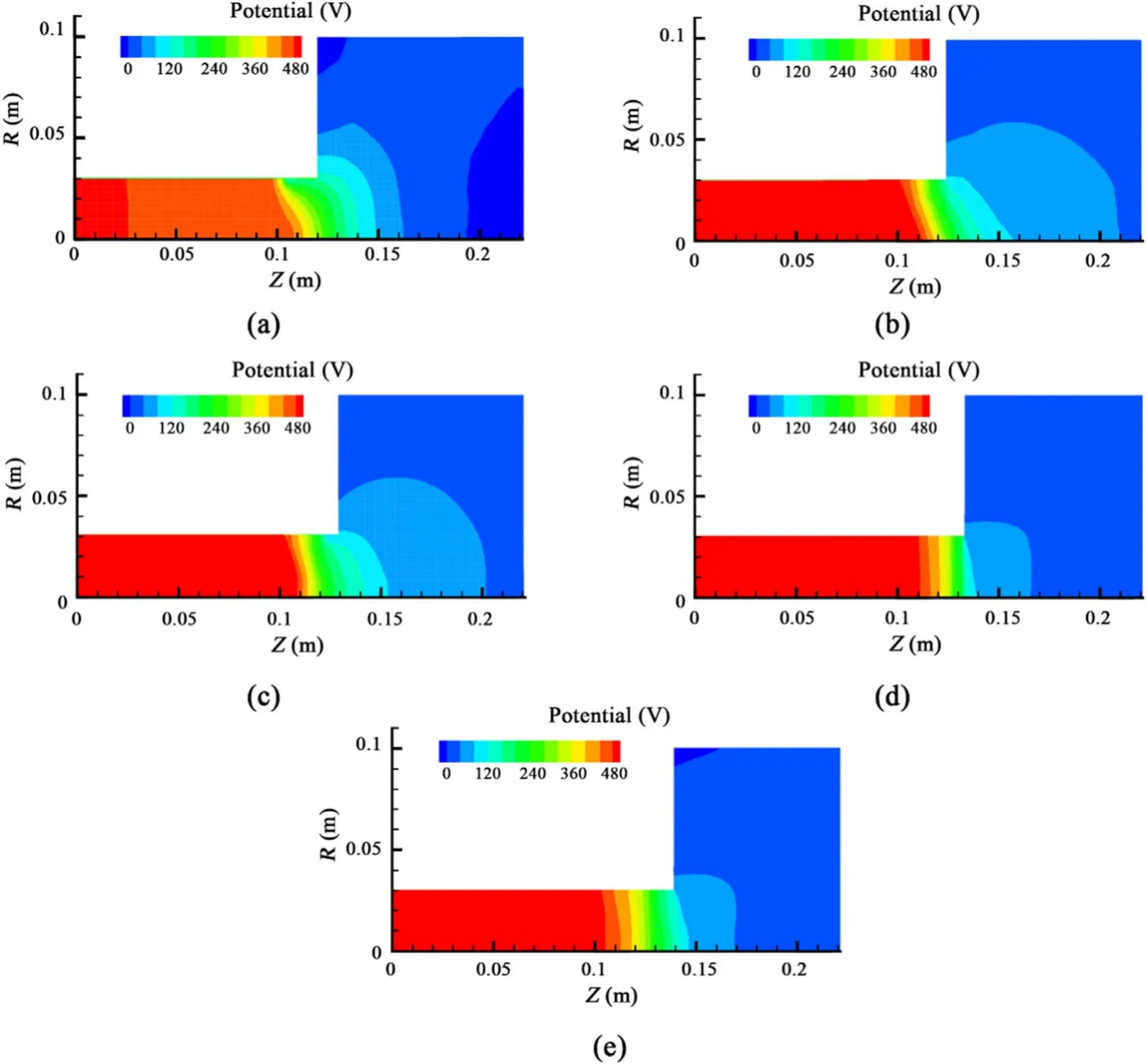
Figure 10.The potential distributions in different magnet length cases.(a) L1=68 mm,(b) L1=73 mm,(c) L1=78 mm,(d)L1=83 mm,and (e) L1=88 mm.
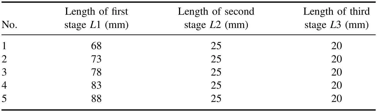
Table 3.The magnetic fields with different magnet lengths.
As can be seen in figure 10(a),the acceleration region(the region with large potential drop)is located near the exit plane in the L1=68 mm case,but its electric field is divergent.With the increase of L1,the direction of the electric field tends to bend towards the axis,and in the L1=78 mm case,the acceleration electric field is well focused.Meanwhile,the change of electric field leads to a variation of ion velocity distributions.As shown in figure 11(b),the distribution of axial high-speed ions extends to move downwards along the axis,and the radial velocity component is decreased significantly.
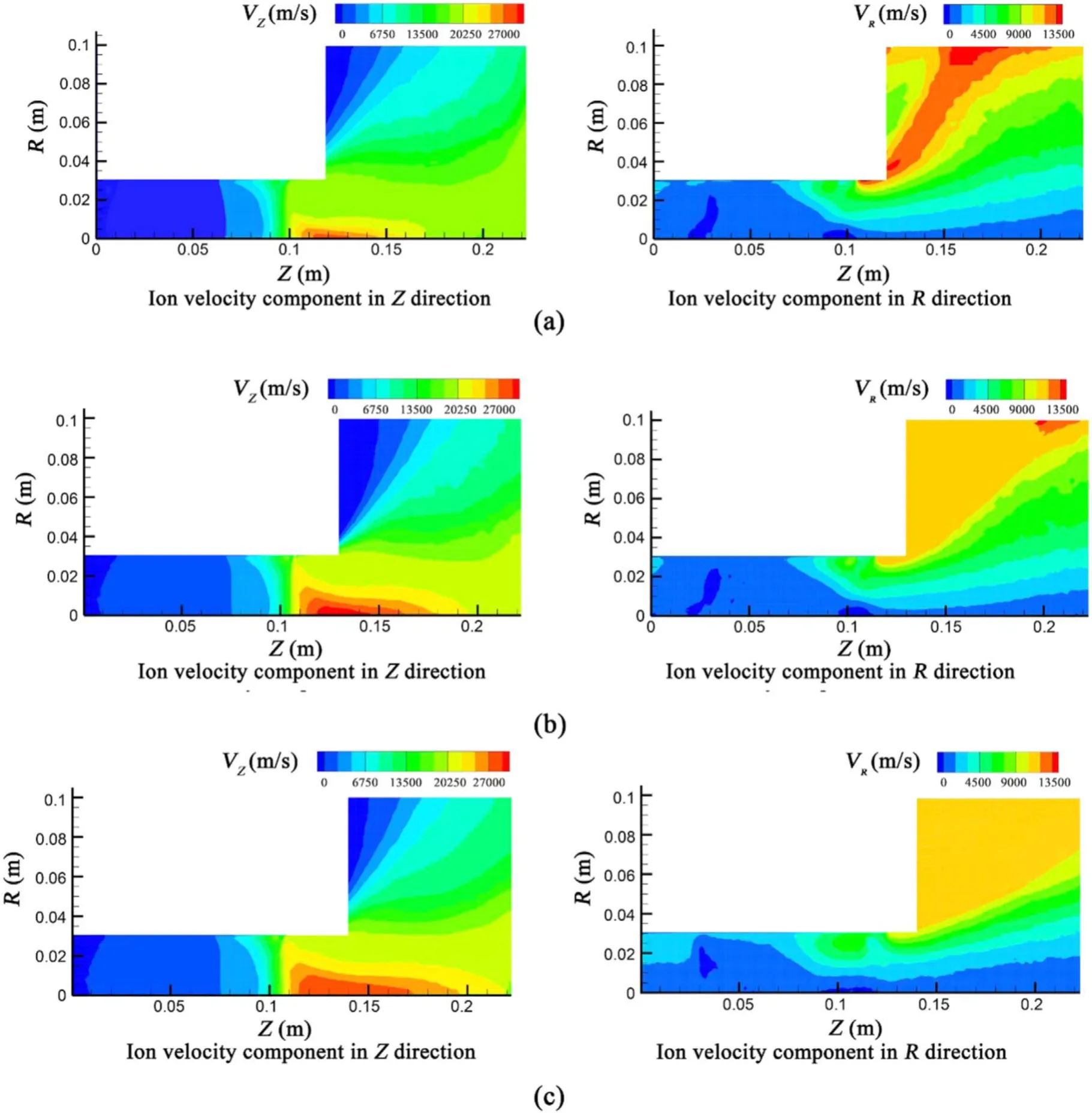
Figure 11.Ion velocity components in different magnet length cases.(a) L1=68 mm,(b) L1=78 mm,and (c) L1=88 mm.
However,when the length of the first stage is increased from 83 mm to 88 mm,the acceleration region moves upstream,and the relative distance between the ionization region and acceleration region is decreased accordingly.This means that some ions cannot acquire high energy from the electric field,and as a result,both the axial velocity components and radial velocity components are decreased,as shown in figure 11(c).It is concluded that the L1=78 mm case is a more efficient magnetic field for the optimization of the acceleration region.
Figure 12 shows the simulation results of plasma density in different magnet length cases.Compared with the condition of L1=68 mm,the thruster has a longer ionization region and higher ionization rate in the condition of L1=78 mm.However,the length of the ionization region is increased with the increase of the first stage length from 78 mm to 88 mm,but the plasma density shows a contrary decreasing tendency,as shown in figure 12.These changes are consistent with the simulation results of electron temperature.In the cases of L1=68 mm and L1=73 mm,the highest electron temperatures are located at the axial position of Z=0.1 mm,as shown in figures 13(a) and (b).The ionization region moves downwards with the increase of the first magnet length from 73 mm to 78 mm,and the position of maximum electron temperature also moves downward accordingly,as shown in figures 13(c) and (d).However,when the length of the first stage is further increased to 88 mm,the ion loss rate at the discharge channel is increased excessively.As a result,the plasma density is decreased,as shown in figure 12(e),and the highest electron temperature moves upwards to the axial position near Z=0.1 mm,as shown in figure 13(e).
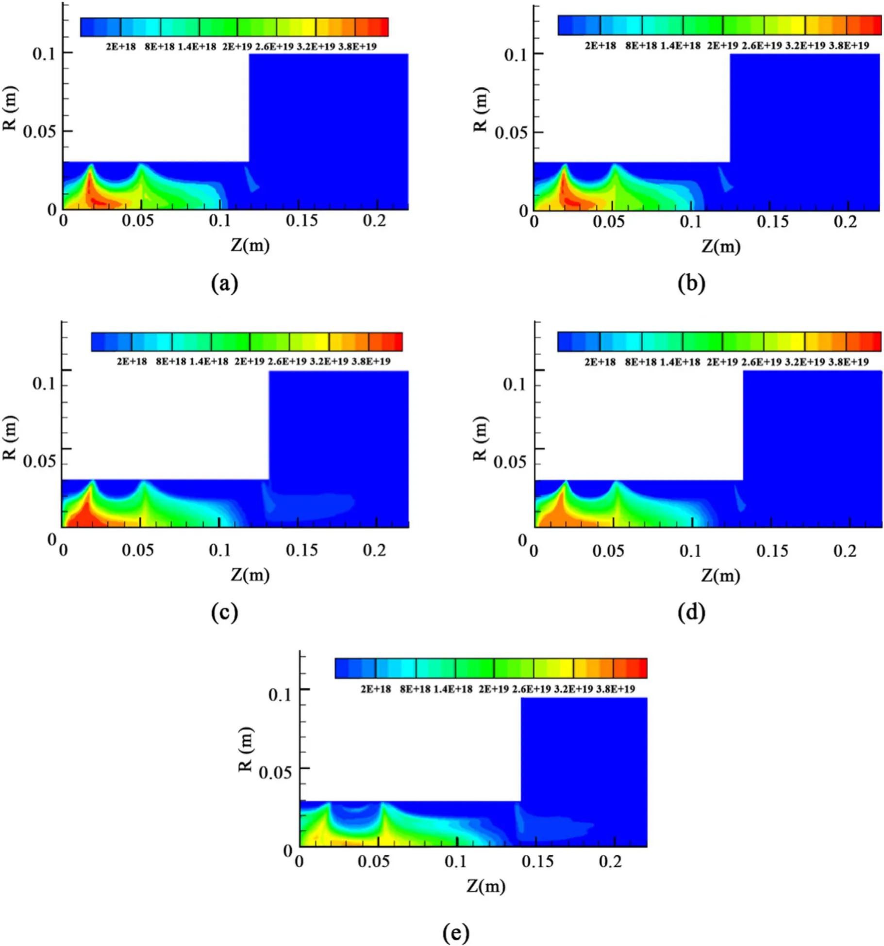
Figure 12.Simulation results of plasma density in different magnet length cases.(a) L1=68 mm,(b) L1=73 mm,(c) L1=78 mm,(d)L1=83 mm,and (e) L1=88 mm.
4.Conclusion
In this paper,the number of magnet stages is firstly studied for the performance optimization of a 5 kW multi-cusped field thruster by the PIC simulation method.The results indicate that the change of the magnet number has no significant effect on the distribution of the accelerating electric field.It mainly affects the ionization process of the thruster,which can be summarized as follows.Firstly,the three-stage magnetic field thruster has two dominant ionization regions,while the twostage magnetic field has only one dominant ionization region.Secondly,the three-stage magnetic field thruster has a stronger electron confinement ability,and the ion energy loss is lower.Thirdly,the three-stage magnetic field shows a higher ionization rate.Therefore,the three-stage magnetic field has a superior magnetic field configuration.In addition,the three-stage magnetic fields with different magnet lengths are also simulated.The results indicate that the change of the magnet length affects both the acceleration region and ionization region,and an optimal accelerating electric field distribution and ionization region distribution could be obtained when the magnet length ratio is 78:25:20.
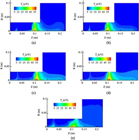
Figure 13.Simulation results of electron temperature in different magnet length cases.(a)L1=68 mm,(b)L1=73 mm,(c)L1=78 mm,(d) L1=83 mm,and (e) L1=88 mm.
Acknowledgments
The authors would like to acknowledge the support of National Natural Science Foundation of China (No.51806011),the Advance Research Project of Equipment Development(No.30501050203),and the Advance Research Project of the Civil Space Program (No.D010509).
 Plasma Science and Technology2020年9期
- Plasma Science and Technology的其它文章
- Special issue on selected papers from CEPC 2019
- Life test research of a high specific impulse Hall thruster HEP-140MF
- Application and development of the pulsed plasma thruster
- Simulation study on the influence of magnetic field in the near-anode region on anode power deposition of ATON-type Hall thruster
- Numerical simulation of the plasma acceleration process in a magnetically enhanced micro-cathode vacuum arc thruster
- Discharge instability in a plasma contactor