Design and FPGA implementation of multi-wing chaotic switched systems based on a quadratic transformation?
2021-03-11 08:32:08QingYuShi石擎宇XiaHuang黃霞FangYuan袁方andYuXiaLi李玉霞
Chinese Physics B
2021年2期
Qing-Yu Shi(石擎宇), Xia Huang(黃霞), Fang Yuan(袁方), and Yu-Xia Li(李玉霞)
College of Electrical Engineering and Automation,Shandong University of Science and Technology,Qingdao 266590,China
Keywords: quadratic transformation,chaotic switched system,FPGA
1. Introduction
At present, design and implementation of multi-wing or multi-scroll chaotic systems with rich dynamic properties on the basis of chaos and circuit theory have become an important research topic.[1–10]The research on the generation of multi-scroll chaotic systems has been relatively mature, but it is still challenging to design the multi-wing chaotic systems.Compared with conventional 2-wing chaotic systems, multiwing chaotic systems not only have more key parameters,but also have nested topological structures.[11–14]They show their unique advantages in relevant fields such as information security and secret communication.[15–18]
In recent decades,a large number of scholars at home and abroad have been devoted to the generation and realization of multi-wing chaotic attractors. For example, Lin et al. constructed a multi-wing chaotic system by introducing the sawtooth wave function to the Lorenz system.[19]Huang et al.proposed a new four-dimensional chaotic system based on Sprott B chaotic system, which can produce not only 2-wing and 4-wing attractors, but also symmetric coexisting attractors.[20]Zhang et al. developed a novel method of constructing multiwing chaotic and hyperchaotic systems by using a unified step function.[21]Chang et al. presented a novel memristorbased chaotic system, and the implemented chaotic attractors had a 2×3-wing, 2×2-wing, and 2×1-wing.[22]Zhong et al. employed a second-degree polynomial memristor function and a sixth-order exponent internal state memristor function to design a three-dimensional memristor-based chaotic system, which formed 2-to-8-wing chaotic attractors.[23]From the above analysis, it is easy to find that most of the literature concentrated on using a particular kind of nonsmooth functions(e.g.,piecewise linear functions,sine functions,stair functions,and saturated functions)or using memristor devices to expand the number of wings. To increase the number of wings rapidly, this paper is devoted to combining the switching function method with the state transformation method to produce a series of multi-wing chaotic attractors.
On the other hand, the research on multi-wing chaotic systems is no longer limited to theoretical analysis and numerical simulations but includes analog or digital circuits realization.[24–29]In actual analog circuits,strict requirements are usually placed on the electronic components,and therefore many factors such as the aging of the devices and the interference of the external environments have a dramatic impact on the dynamics of the considered system. However, the use of field programmable gate array(FPGA)digital systems can well avoid these problems. In regard to FPGA implementation, there are usually three methods. The first is to use the Verilog HDL or HDL code directly to describe the chaotic system.[30–32]The advantage of this method is that the codes have good portability and versatility, but the programming is quite complicated. The second is to use the DSP Builder to construct a discrete model for the considered chaotic system and then output HDL codes.[33,34]This method adopts graphical programming, and hence the code is relatively simple to write, but the portability is low. The third is to use the HDL Coder to generate Verilog HDL or HDL code in the Matlab/Simulink environment.[35,36]This method combines the advantages of the first and the second,but the library functions are still not perfect,and some computing functions are difficult to implement. With careful consideration of these three methods,the Verilog HDL code is used directly to describe the state equations of the considered system. We convert the generated digital chaotic sequence into an analog voltage signal by the digital-to-analog converter(DAC)module,and then the phase diagrams of the chaotic attractors can be observed on the oscilloscope.
In summary,we propose a combined method in this paper to generate multi-wing chaotic attractors. More precisely,we combine the quadratic transformation with a switching function to expand the number of saddle-focus equilibrium points,and meanwhile the FPGA is built to confirm the numerically simulations.
Comparing with the existing literature,the innovations of this paper are as follows.
(1)Most of the published literature used only one method to expand the number of wings, while this paper combines two different techniques to generate the multi-wing chaotic attractors. The proposed system can produce 6-to-8-12-16-wing attractors by adjusting the switching function and it makes the generation of multi-wing chaotic attractors easier.
(2)Most of the chaotic attractors in the published literature are arranged in linear or grid form.In contrast,the chaotic attractors generated in this paper are distributed in a fish-bone like structure,and the topological structures are more complicated.
(3)In FPGA implementation,we use the three-stage state machine design to write Verilog HDL code directly to realize the chaotic switched systems. Compared with the existing work,there exist more difficulties in the FPGA design.
The rest of the paper is organized as follows.In Section 2,by using the quadratic transformation scheme, the state variables of a 2-wing chaotic system are transformed into another group of state variables to generate a 4-wing chaotic attractor,and it is shown that the number of wings is equal to the number of the saddle-focus equilibrium points. In Section 3,the number of the saddle-focus equilibrium points is increased by constructing a kind of switching functions. Thus, the previously generated 4-wing chaotic attractor can be transformed into a series of attractors with 6-to-8-12-16 wings, which are also testified by the Lyapunov exponent spectra, Poincar′e maps,and bifurcation diagrams. In Section 4,the Verilog HDL code for the multi-wing switched chaotic system is designed. By using FPGA,the chaotic attractors are observed on the oscilloscope,which verifies the feasibility of our design method.
2. A four-wing chaotic system based on the quadratic transformation
Consider a three-dimensional 2-wing chaotic system[37]as follows:
where u,v,w are the state variables, and a1,a2,a3,a4are the system parameters.
First, the quadratic transformation[38]is applied to system(1). The specific steps are as follows.
Step 1:Denote the space transformation as Φ0=x+yi,where Φ0is a complex number with x and y as its real and imaginary parts. Introduce the quadratic transformation Φ1as follows:

where(x2?y2)is the real part of Φ1,and 2xy is the imaginary part of Φ1.
Step 2:Let the state variables u and v be the real and imaginary part of Φ1,respectively. And,the state variable w is replaced by a new variable z,that is

Step 3:In view of Eq.(3),the relations between the state variables u,v,w and x,y,z can be represented by

Step 4:By the matrix inverse algorithm,equation(4)can be further rewritten as

which is equivalent to

Thus, based on the quadratic transformation, system (1) is transformed into system (6). Next, the characteristics of the equilibrium points and their eigenvalues are analyzed.
Set the parameters as a1=22,a2=12,a3=6,a4=8.Then, the equilibrium points and the corresponding eigenvalues of system (6) are displayed in Table 1. The distribution of those equilibrium points in x–y plane is shown in Fig.1,in which the symbol ‘?’ represents the equilibrium points of system(6).

Table 1. The equilibrium points and eigenvalues of system(6).

Fig.1. Distribution of the equilibrium points of system(6).

Fig.2. The chaotic attractor of system(6): (a)x–y plane;(b)x–z plane.
It can be seen from Table 1 that system (6) has four saddle-focus equilibrium points of index 2. Thus, it can generate a 4-wing chaotic attractor. For given initial values[x0,y0,z0]T=[1,1,1]T, the 4-wing chaotic attractor is shown in Fig.2.
Meanwhile, the three Lyapunov exponents of system(6)are LE1=1.2201, LE2=?0.0017, and LE3=?17.2275.According to the formula DL=2+(LE1+LE2)/|LE3|, the Lyapunov dimension is DL=2.0707,which suggests that the attractor is fractional.[39]
3. A switched chaotic system based on a class of switching functions
Clearly, for system (6), there exists a one-to-one correspondence between the number of saddle-focus points and the number of wings. In this section, by constructing a class of switching functions, the number of saddle-focus equilibrium points with index 2 on both sides of the origin can be increased. It means that the number of wings of the chaotic attractors can be further expanded.
First, a switched system is proposed on the basis of the transformed system(6)by replacing the variable x in the right sides of Eq.(6)by Tx,which can be described by

in which Txis a switching function of the state variable x,and also it is symmetric about the origin.
Given the initial value[x0,y0,z0]T=[1,1,1]Tand keeping the values of a1,a2,a3,a4unchanged, the switching function Txis designed to adjust the distribution and the number of the saddle-focus equilibrium points. Thereby different kinds of multi-wing chaotic attractors can be generated. Here are the details.
Case 1:Take
Set the parameter e=5, the equilibrium points of system(7)with the switching function(8)are displayed in Table 2. The distribution of those equilibrium points in x–y plane is exhibited in Fig.3,in which the symbol‘?’represents the equilibrium points obtained in case 1 and‘?’denotes the equilibrium points of the original system (6). Obviously, the equilibrium points have been expanded from the previous four to six.
Thus,system(7)has six saddle-focus equilibrium points and therefore can generate a 6-wing chaotic attractor,which is shown in Fig.4.
In case 1, the three Lyapunov exponents of the switched chaotic system are LE1=1.8000,LE2=0.3210,and LE3=?18.1241. And, the Lyapunov dimension of the attractor is increased to 2.1170.

Fig.3. Distribution of equilibrium points of system(7)in case 1.
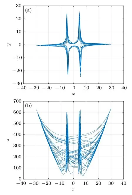
Fig.4. The chaotic attractor of system (7) in case 1: (a) x–y plane;(b)x–z plane.
Case 2:Take

When designing the switching function Txas Eq. (9), set the parameter e=5,the equilibrium points of system(7)are displayed in Table 3. The distribution of these equilibrium points in x–y plane is presented in Fig.5, in which the symbol ‘×’represents the equilibrium points in case 2 and‘?’denotes the equilibrium points of the original system(6). From Fig.5,we can see that the equilibrium points have been expanded from the previous four to eight.

Table 2. The equilibrium points and eigenvalues of system(7)in case 1.

Table 3. The equilibrium points and eigenvalues of system(7)in case 2.
Fig.5. Distribution of equilibrium points of system(7)in case 2.
In this case, system (7) has eight saddle-focus equilibrium points and therefore produces a 8-wing chaotic attractor,which is demonstrated in Fig.6.
In case 2, the three Lyapunov exponents of the switched chaotic system are LE1=2.8066,LE2=?0.1807,and LE3=?18.6331. Thus, the Lyapunov dimension of the attractor is increased to 2.1409.

Fig.6. The chaotic attractor of system (7) in case 2: (a) x–y plane;(b)x–z plane.
Case 3:Take

Set the parameter e=5,the equilibrium points and their eigenvalues of system (7) with the switching function (10) are shown in Table 4. The distribution of those equilibrium points in x–y plane is demonstrated in Fig.7,in which the symbol‘△’represents the equilibrium points in case 3 and‘?’denotes the equilibrium points of the original system (6). Obviously, the equilibrium points have been expanded from the previous four to twelve.
Thus, in this case, system (7) has twelve saddle-focus equilibrium points and can generate a 12-wing chaotic attractor,which is demonstrated in Fig.8.
In case 3, the three Lyapunov exponents are LE1 =4.0855,LE2=?0.8212,and LE3=?19.2708,respectively.The Lyapunov dimension of the attractor is increased to 2.1694.

Fig.7. Distribution of equilibrium points of system(7)in case 3.

Fig.8. The chaotic attractor of system (7) in case 3: (a) x–y plane;(b)x–z plane.
Case 4:Take
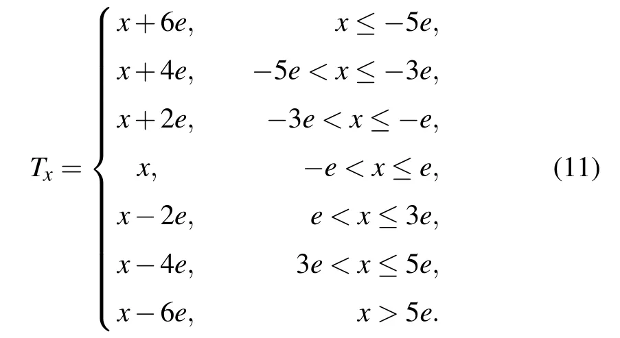
Set the parameter e=5,with the switching function(11),the equilibrium points and their eigenvalues of system(7)are displayed in Table 5. The distribution of those equilibrium points in x–y plane is exhibited in Fig.9, in which the symbol ‘□’represents the equilibrium points obtained in case 4 and ‘?’denotes the equilibrium points of the original system(6). Obviously, the equilibrium points have been expanded from the previous four to sixteen.
Thus, system (7) has sixteen saddle-focus equilibrium points and therefore can generate a 16-wing chaotic attractor,which is shown in Fig.10.
In case 4, the three Lyapunov exponents are LE1 =4.5384,LE2=?0.9897,and LE3=?19.5547,respectively.Therefore, the Lyapunov dimension of the attractor is increased to 2.1815.

Table 4. The equilibrium points and eigenvalues of system(7)in case 3.

Table 5. The equilibrium points and eigenvalues of system(7)in case 4.

Fig.9. Distribution of equilibrium points of system(7)in case 4.

Fig.10. The chaotic attractor of system (7) in case 4: (a) x–y plane;(b)x–z plane.
4. Dynamic analysis of the switched system
In this section, the complex dynamic behaviors of the switched system will be studied. By analyzing the Poincar′e maps,the Lyapunov exponent spectra,and the bifurcation diagrams,some detailed dynamic properties for the switched system(7)will be revealed.
4.1. Poincar′e maps
Fixing a1=22,a2=12,a3=6,a4=8,e=5,and the initial value[x0,y0,z0]T=[1,1,1]T,taking z=200 as the crossing plane, the Poincar′e maps of system (7) are displayed in Fig.11. It can be seen from Figs. 11(a)–11(d) that the four different Poincar′e maps are consistent with the previously obtained 6-to-8-12-16-wing chaotic attractors, which verify the existence of the multi-wing chaotic attractors.
4.2. Lyapunov exponent spectra and bifurcation diagrams

Fig.11. Poincar′e map on the cross-section z=200: (a)case 1;(b)case 2;(c)case 3;(d)case 4.
Besides, taking the threshold parameter e as the bifurcation parameter and keeping the values of the other parameters unchanged, the Lyapunov exponent spectra and bifurcation diagrams of system(7)for the four cases are displayed in Figs.12 and 13.Note that the parameter range for e is selected as 0 <e <25 in the simulations. From Figs.12 and 13,it can be seen that system(7)is chaotic for a large range of parameter 1 <e <25. In addition,an interesting phenomenon can be observed, that is, the bifurcation diagrams consist of 2,3,5,7 branches, respectively, which are entirely consistent with the number of the segments in the switching functions.
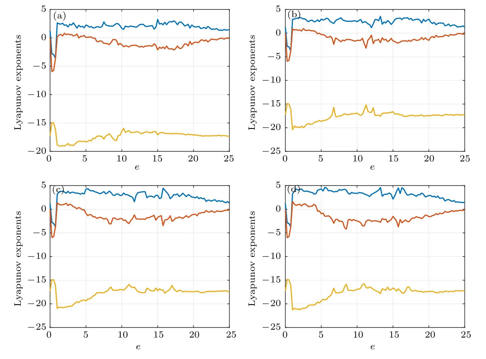
Fig.12. Lyapunov exponent spectra of system(7): (a)case 1;(b)case 2;(c)case 3;(d)case 4.

Fig.13. Bifurcation diagrams of system(7)with respect to e: (a)case 1;(b)case 2;(c)case 3;(d)case 4.
5. FPGA implementation
In this section, the Verilog HDL code is designed for switched chaotic system (7). Meanwhile, the 6-to-8-12-16-wing chaotic attractors are implemented by FPGA.In particular, the improved Euler algorithm is used to describe the system first. Then, a three-stage state machine is employed to describe the whole iterative process. Finally, the output digital chaotic sequences are transmitted to DAC, and the phase diagrams of the chaotic attractors are observed from the oscilloscope.
Before designing the model for the system, the dynamic range of the variables should be considered first. In order to prevent the values of the variables from overflowing,we must compress the system first. The compression factors for variables x,y,z are respectively taken as K1=25,K2=25,K3=29.Thus, the dimensionless state equation of system (7) is obtained as follows:

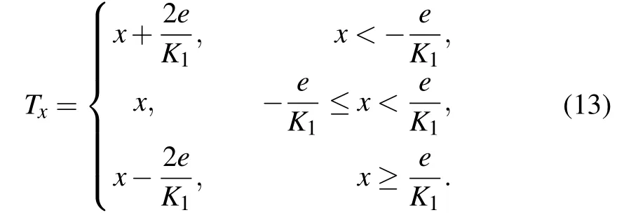
and notice that all the constant items and the switching threshold in Txare reduced to 1/K1of their original value. Taking case 2 as an example. When the system is compressed,Txcan be further rewritten as
Next, the k-step input vector of the system is denoted as Xk=(xk,yk,zk)T,the right-side function of the state equation is marked as F(Xk), and the step size of the iteration is set to h=1/128. Then, the discretization equation of the chaotic system is obtained as
Xk+1=Xk+F[Xk+F(Xk)×0.5h]×h.
First of all,we use 24-bit fixed-point numbers to describe the variables of the system. In these 24-bit binary numbers,we use 18 of them to represent decimals.Then,the three-stage state machine of the system is designed. The so-called threestage state machine uses three always modules. Among them,the first always module uses synchronous timing to describe the state transition. The second always module uses combinational logic to judge the state transition conditions and to describe the state transition rules.The third always module describes the state output. By using the state machine,the jump of the iteration operation can be easily realized,and each step of the iteration can be described in different state processes.The design of the state machine for the system is shown in Fig.14.
In S0 state, the switching function Txcan be realized by the selection output process of the multiplexer. Following the state jump process, the addition, subtraction, multiplication and division operations in the iterative process can be implemented by the status bits S1 to S20. Thus,in S21 state,we get Xk+0.5or Xk+1of the k-step iteration. If jump position=0,then output Xk+0.5,and the state machine jumps to the S0 state to perform another round of calculation;if jump position=1,then output Xk+1,Xk+1is the output vector of the k-step iterative operation,which corresponds to the output of the chaotic sequence of the system. In S22 state, we add a 24-bit positive number to Xk+1to ensure that the input values to the DAC module are all positive. Finally, because the DAC module is 14 bits, it implies that we should intercept [21:8] bits of data as the final output.
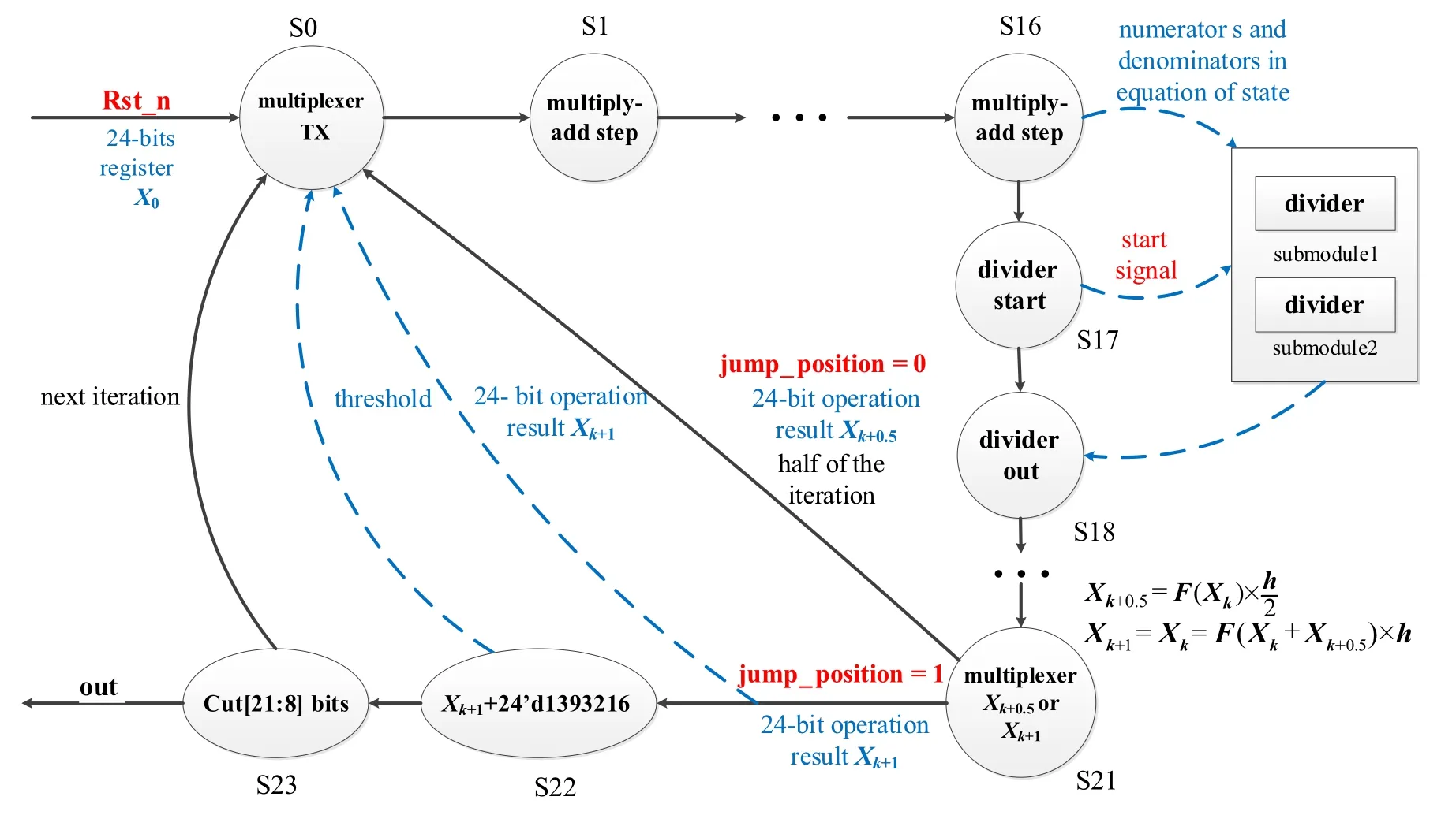
Fig.14. State machine description of the system.

Fig.15. Wiring diagram and phase diagrams of the generated chaotic attractors: (a)wiring diagram between AX301 and oscilloscope;(b)6-wing attractor in case 1;(c)8-wing attractor in case 2;(d)12-wing attractor in case 3;(e)16-wing attractor in case 4.
Thereafter, we compile the Verilog HDL code in Quartus II software and download it to the FPGA development board after synthesis. The FPGA development board that we use is AX301 board of Alinx,and the board carries Altera Cyclone IV EP4CE10F17C8 chip. Moreover, the development board is also equipped with a 14-bit DAC module AN9767,which can convert the digital chaotic sequence generated in the FPGA chip into analog voltage signals for output. Wiring diagram between AX301 and oscilloscope is shown in Fig.15(a),and the observed phase diagrams of the 6-to-8-12-16-wing chaotic attractors are displayed in Figs. 15(b)–15(e), which confirm the existence of the chaotic attractors.
6. Conclusion
In this study,a multi-wing chaotic switched system with complicated topological structures is proposed on the basis of a 2-wing chaotic attractor via a combined method,and meanwhile the multi-wing chaotic attractors are realized by FPGA.In brief, the core of the design method is the combination of a quadratic transformation and a switching function. By the means of Lyapunov exponent spectra, bifurcation diagrams and Poincar′e map analysis, some interesting dynamical phenomena are revealed. Besides,in the FPGA digital circuit design, Verilog HDL hardware description language is used to describe the system,and each step of the iterative operation is realized in the designed state machine. The observation of the multi-wing chaotic attractors on the oscilloscope verifies the validity of the proposed design method.
登錄APP查看全文

- Chinese Physics B的其它文章
- Statistical potentials for 3D structure evaluation:From proteins to RNAs?
- Identification of denatured and normal biological tissues based on compressed sensing and refined composite multi-scale fuzzy entropy during high intensity focused ultrasound treatment?
- Folding nucleus and unfolding dynamics of protein 2GB1?
- Quantitative coherence analysis of dual phase grating x-ray interferometry with source grating?
- An electromagnetic view of relay time in propagation of neural signals?
- Negative photoconductivity in low-dimensional materials?