Influence of an inserted bar on the flow regimes in the hopper?
2021-03-11 08:34:10YiPeng彭毅ShengZhang張晟MengkeWang王夢柯GuanghuiYang楊光輝JiangfengWan萬江鋒LiangwenChen陳良文andLeiYang楊磊
Chinese Physics B 2021年2期
Yi Peng(彭毅), Sheng Zhang(張晟), Mengke Wang(王夢柯),, Guanghui Yang(楊光輝),Jiangfeng Wan(萬江鋒), Liangwen Chen(陳良文), and Lei Yang(楊磊)
1Institute of Modern Physics,Chinese Academy of Sciences,Lanzhou 730000,China
2University of Chinese Academy of Sciences,Beijing 100049,China
3East China University of Technology,Nanchang 330000,China
Keywords: hopper flow,inserted bar,flow type transition,free surface,velocity distribution
1. Introduction

According to the motion state, a steady hopper flow can be divided into four flow regions.[8]There is a bulk flow region except for near the bottom, where the particles move downward uniformly.Due to the existences of durative force chains,the granular temperature is low. If the inclination of the upper surface is larger than the inter-friction angle,this bulk flow region can be further divided into two sub-regions: mass flow region and avalanche flow region. At the end of the bulk flow region,there is a converging shear region with a dilation.[12]In this region there are shears between particles and the granular temperature is much higher than that in bulk flow region.[13]Consequently,particles are no more under shear and fall freely in the free falling region,where a few collisions occur.[14]The stagnant region appears in lower corners where the particles experience very slow creeping,[15]where the volume fraction is larger than those in other three regions. There is a sliding surface between the stagnant zone and converging shear region.[16]
To control the hopper flow,the effect of an insert has been studied for decades.[17–21]Zuriguel et al.’s experiment shows the presence of insert above the outlet reduces the probability of clogging.[22]The existence of insert will also result in the transition from funnel flow to mass flow. Moreover, it leads to the changes of flow rate and flow field. Under the insert,a free surface forms during the discharging, which was studied in Li et al.’s work.[23]The simulations showed that the free surface has a steady shape which could be fitted to be a paraboloid. Recently, Wojcik et al. performed a large scale experiment of hopper flow with inserts and found that the recommendations based on previous small scale studies are no longer a good solution in large scale tests.[24]As an obvious stagnant region exists in the hopper flow where the motions of particles are nearly static. One question is if there is a resemblance between this flow and the surface flow upon an erodible heap.[25,26]In this heap flow,it is found that the inclination angle depends on the flow rate and is influenced by sidewalls.There is a nearly linear profile of velocity along the flowing direction in flowing layers and the velocity decays exponentially in the heap.[27]This decay can be explained by the stress distribution being affected by the wall friction,that is,it has a potential correlation with Janssen effect.[28]In a new concept of dense granular-flow target, there also exists a free surface under an inner tube.[29]The shape and velocity distribution are specially concerned because of the great influences on the capacity of heat remove.
Here we provide an experimental study of the free surface under an insert in the hopper. A long bar is inserted in an asymmetric hopper to present the details of the free surface.We study the influence of the bar on the flow rate,the shape of the surface,and the velocity field.
2. Methods
As shown in Fig.1,the setup for experiments is a rectangular bin(200 cm×60 cm×6 cm). A bar, whose thickness is 3 cm, is inserted from the right side to create two chambers,that is, the upper chamber and the lower chamber. The distance between the lower surface of the bar and the bottom,H,can be adjusted in unit of 3 cm.The expanding distance can be adjusted and the height can be changed in 3 cm. The interval between the bar and walls is less than 3 mm. In the experiments,spherical plexiglass particles are used with the dispersity of diameter d=6±0.02 mm.The outlet size is controlled by moving the bottom plate. In this study,there are three controlling parameters: D0,D1,and H. For simplicity,each case is denoted by D1–D0–H. For example,case 10–2–36 presents the case with D1=10 cm, D0=2 cm, and H =36 cm. The weight of outflow is recorded by using an electronic balance with precision±0.1 g in a recording frequency 10 Hz. When the flow is steady, a time-averaged flow rate is obtained by linear fitting of the cumulative weight. To against the electrostatics,anti-static spray is used and the humidity is controlled to be 45%during the experiments.
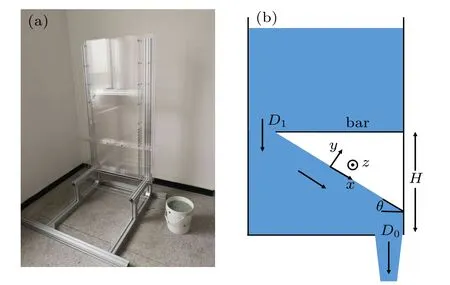
Fig.1. (a) The equipment in this study. (b) A schematics of a dense flow(see the definition in text)with an asymmetric bar. The coordinate frame is plotted.
A fast-industrial camera(Revealer 2F04)is employed to shoot the discharging process. The shooting area is around 500 mm×400 mm and the image resolution is 2240×1640.The velocity measurement of the particles close to the sidewall is based on their moving tracks. With visible diameter of the particle in the picture frame of video, the position of the particle can be recognized successfully. If the same particle can be tracked within subsequent frames, the velocity vector of the particle is obtained. In the calculation, we also consider different corrections, such as the distortion of the lens system and rotation of the camera to the ground. In the surface of rapid flows, the particles in this region move faster,so a high 800 frames per second (FPS) resolution is adopted for tracking. Here we use the CSRT algorithm(built-in function in OpenCV) for particle tracking. This algorithm called CSRDCF++ (discriminative correlation filter with channel and spatial reliability)is the best performing real-time tracker in the Visual Object Tracking VOT2017 challenge.[30]
3. Results and discussion
In the beginning, the lower chamber is filled and the up chamber is loaded with 400 mm-high particles. After the opening of lower outlet D0, according to the variation of instantaneous flow rate with time,the flowing process can be divided into two stages. The first stage is for the partial drainage of the lower chamber and the formation of an inclined free surface. In this stage, there is an obvious fluctuation of the flow rate.The second stage is for the stable flow that the particles in the upper chamber flow into the lower chamber continuously.As shown in Fig.2, with small H, finally there is a clogging after stage one. The slope,which could be seen as a repose angle θrhere,is ~19.5?. As H increases,a surface flow appears which is defined by the observation that the space of the lower outlet is not full of particles. This means, there is no interaction between the jet and right sidewall. It is natural to deduce that in this surface flow regime,the flow rate does not depend on the lower outlet size D0. This flow rate saturates when H exceeds 30 cm. Then the flow above the lower outlet becomes dense and the surface in the lower chamber can be presented as an incline.
In the dense flow regime,we can also confirm the Beverloo scaling law Q ~(D0?kd)αby varying outlet size D0(see Fig.3). Accordingly, the hopper is quasi-two-dimensional.The fitting power α =3/2 and coefficient of‘empty annulus’k = 0.5. This result shows that the scaling law is not broken by inducing an obstacle.[31,32]The empty annulus here is only one half of the particle diameter,which is consistent with the original assumption adopted by Brown and Richards.[33]However, this value is smaller than the usual value of threedimensional hopper flow[3]and also smaller than the value in previous simulations of the quasi-two-dimensional hopper flow.[31]It is worth noted that there is still a stable dense flow with D0=1.3 cm,which is just 2.1 times of the particle diameter,and correspondingly the flow rate is 78.3 g/s.

Fig.2. Variations of flow rate and inclination of surface by varying H. Three flow regimes (clogging, surface flow, and dense flow) are recognized. D1=10 cm and D0=4 cm are adopted.
The formation of the surface is shot by a camera during the flow and analyzed by a visualization code(see Section 2).It shows that in both surface flow and dense flow regimes,the variation of the surface over time is small and the surface can be presented as a simple slope. In the surface flow regime,the inclination decreases to 22?when H decreases to 21 cm.In the dense flow regime, where the outlet size D0is fixed at 4 cm,the inclination of the slope is 27.8?and seems to be invariable with changing H. If we fixed H and changed the outlet size D0,the inclination increases from 23.8?to 29.2?when D0increases from 1 cm to 5 cm (Fig.3). It also indicates that the inclination is unchanged when D0≥5 cm, regardless of the continued increase of the flow rate.
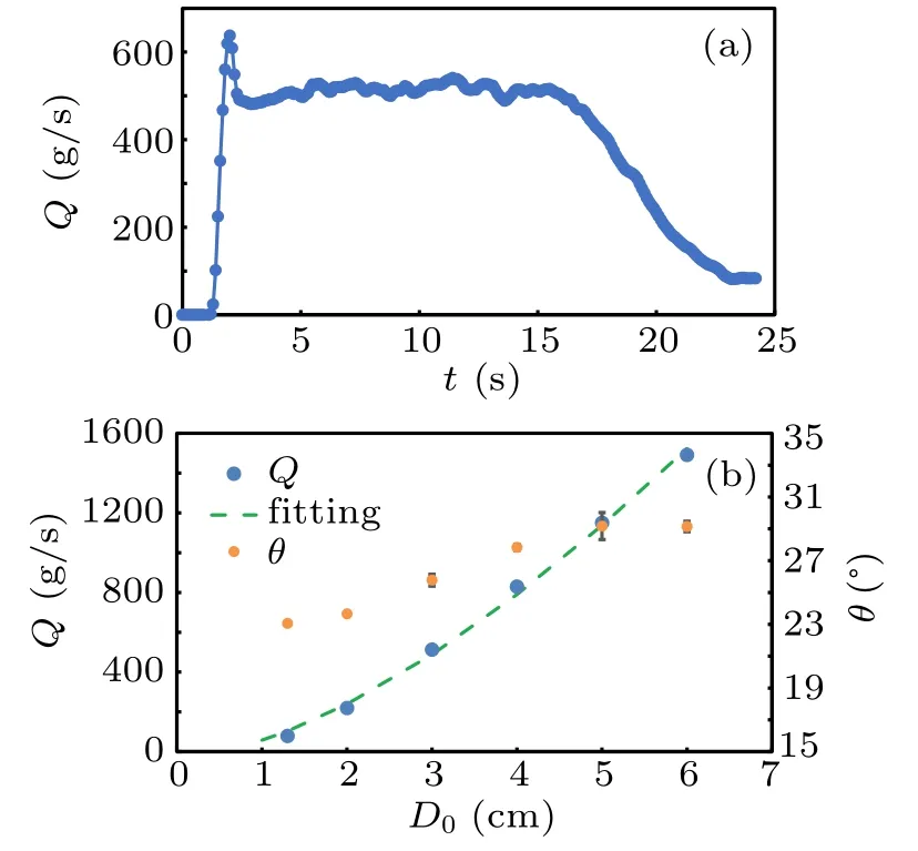
Fig.3. (a) Profile of Q with time t where D0 =3 cm, D1 =10 cm,and H=36 cm. (b)Variation of flow rate and inclination in dense flow regime by varying lower outlet size D0. H=36 cm and D1=10 cm are adopted.


Fig.4. (a) Profiles of velocity vx with depth from the surface. Triangles denote the heap flow. Dotted lines are for visual guide. (b)Scaling relation between Q and h.
For the existence of an inserted bar,one interesting issue is whether the connectivity of the dense flow between upper and lower chambers will be affected by the bar. It is trivial to know that this connectivity will be blocked if D1<1d,leading to a clogging. Here we set D0=4 cm and measure the variation of the flow rate with decreasing D1. The results show that the flow rate is affected if D1<3.5 cm,leading to an obvious reduction of the flow rate(see Fig.5).It is quite surprising that this critical value of D1is even smaller than the fixed value of D0,which is confirmed in the additional cases with D0=6 cm.A potential explanation is that for the flow across D1,there is no‘empty annulus’.
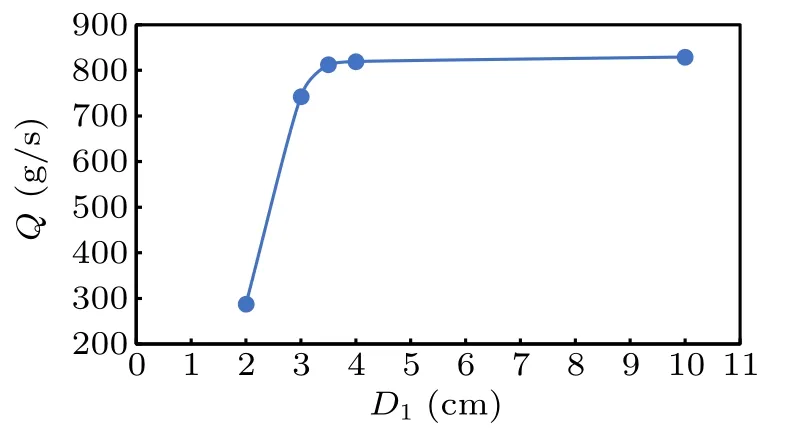
Fig.5. Variation of flow rate in dense flow regime by varying upper outlet size D1. H=36 cm and D0=4 cm are adopted.
Another question is whether there is a jump of flow rate for the transition from clogging to surface flow.For this equipment, owing to the fact that H can be only adjusted in unit of 3 cm, we can drive the system towards the clogging state by increasing D1to let the aspect ratio H/(D ?D1?D0)approach to tanθr. According to the clogging transition happening between H = 18 cm to H = 30 cm, here we fix H =21 cm and D0=4 cm and find that there is a clogging when D1≤3.5 cm(see Fig.6). Thus the critical aspect ratio H/(D?D1?D0)=21/52.5=0.4 which provides the corresponding angle of 21.8?and the minimum flow rate in this system is 18.2 g/s with D1=3.6 cm. This angle is 2?larger than the repose angle θrin the clogging flow,which is attributable to dilatancy[37,38]and is often the angle of metastable state in previous reports.[39,40]Additionally, there is a roughly linear dependence of D1on the flow rate,so is the inclination of the surface. These results suggest the influences of fore and rear boards,which are similar in the heap flow(see below).

Fig.6. Variation of flow rate in surface flow regime by varying upper outlet size D1. H =21 cm and D0 =4 cm are adopted. Dotted line is for visual guide. Insert: variations of inclination of surface.

Fig.7. Inclination of free surface vs. flow rate in heap flow. H=36 cm and D0=8 cm are adopted. Dotted line is for visual guide.
4. Conclusion
We investigated the influence of a bar on a granular flow in a rectangular bin experimentally. We found the varying of the height of the bar results in the transitions from clogging to a dense flow via a surface flow regime. Below the bar, the free surface of flow can be described as a slope. It seems that the change of the flow rate from clogging to surface flow is a jump and the minimum flow rate is 18.2 g/s. The slope of surface for this jump is larger than the tangent of repose angle.In the dense flow regime,the Beverloo scaling law will remain valid with the introduction of the bar. The slope of surface will saturate with increasing flow rate. The velocity distribution was analyzed and is consistent with that in a heap flow.To ensure the connectivity of the flow, the allowable distance between the bar and sidewall can be slightly smaller than the outlet size. Finally, we produced a heap flow in this bin and found a linear dependence of the flow rate on the slope of surface.

- Chinese Physics B的其它文章
- Statistical potentials for 3D structure evaluation:From proteins to RNAs?
- Identification of denatured and normal biological tissues based on compressed sensing and refined composite multi-scale fuzzy entropy during high intensity focused ultrasound treatment?
- Folding nucleus and unfolding dynamics of protein 2GB1?
- Quantitative coherence analysis of dual phase grating x-ray interferometry with source grating?
- An electromagnetic view of relay time in propagation of neural signals?
- Negative photoconductivity in low-dimensional materials?