栓釘連接雙鋼板-混凝土組合剪力墻抗剪性能數值分析
2021-03-11 08:49:38韋芳芳朱有華喻君
土木建筑與環境工程 2021年1期
韋芳芳 朱有華 喻君

摘 要:雙鋼板混凝土組合剪力墻結構是一種新型高層建筑抗側力構件,具有良好的應用價值和發展前景。根據其他學者的試驗結果,結合相關文獻中連接件的剪切滑移公式,擬合得出抗剪栓釘的剪力-滑移關系,并通過有限元軟件ANSYS建立了雙鋼板混凝土組合剪力墻的有限元模型。以分析組合剪力墻的剪切性能為目的,采用相關假定簡化模型并與已有試驗結果對比,驗證有限元模型的合理性。采用驗證過的有限元模型進一步對雙鋼板混凝土組合剪力墻的抗剪性能進行非線性分析,研究抗剪栓釘間距、鋼板厚度、混凝土板厚度、混凝土強度等級及組合剪力墻跨高比等主要參數的影響。數值結果表明,鋼板、混凝土板厚度以及混凝土強度對雙鋼板混凝土組合剪力墻的抗剪承載力的影響最顯著,而栓釘間距會影響組合剪力墻的受剪破壞模式。
關鍵詞:組合剪力墻;剪力連接件;抗剪性能;數值分析;組合結構
1 Introduction
As the lateral load is considered to be the dominant factor in the structural design of a high-rise building, the lateral force-resisting system is the most important part of a high-rise building[1]. Concrete filled double steel plate composite walls (CFDSPCWs) with shear stud connectors are proposed as a new type of shear wall structure[2-3]. The steel-concrete-steel (SCS) wall developed by the Corus Company[4] consists of two steel plates and a concrete core. The SCS wall integrates the advantages of steel and concrete and has a high shear resistance and lateral stiffness. The SCS wall is constructed using shear connector rods attached to both steel plates through a high-speed rotational friction weld process. However, the interaction between the concrete and steel plates is too complicated to be used in a high-rise building. In order to simplify the interaction of the steel plates and the concrete core of the composite shear wall, the CFDSPCW with shear stud connectors was developed by Nie et al., and is suitable for high-rise buildings[5].
At present, there are dozens of buildings with CFDSPCW structures used as the lateral force-resisting components worldwide, which are mainly distributed in high seismic intensity regions such as North America and Japan. There are some domestic buildings using this CFDSPCW structure such as the main structure of an Avalokitesvara statue[5], the tube structure of the Yancheng TV tower[6], and the main structure of the Guangzhou East Tower[7], which indicates that the use of this type of structure is still in the early stage in China.
Due to its good mechanical performance, convenient construction and high reliability, the stud connector has become the most widely used shear connector and is also used in the CFDSPCW structure studied for this paper. In addition, to improve the integrity of the composite shear wall and strengthen the lateral restraint of the internal concrete, stud connectors are welded onto each steel plate. Moy et al.[8] conducted a push-out test of stud connectors and studied their shear stiffness and strength. Nie et al.[7, 9]? experimentally investigated the seismic performance of CFDSPCWs with stud connectors under different axial compression ratios, shear span to effective depth ratios and intervals between stud connectors. Their results showed that the CFDSPCW had good ductility and energy dissipation capacity, and thus could potentially be applied in high-rise buildings.
There are also studies of the shear resistance of steel-concrete composite walls[10-15]. Wei et al.[10] carried out numerical analyses and theoretical analyses on CFDSPCWs using friction welded transverse bars as shear connectors and proposed a formula to calculate the shear capacity of the corresponding CFDSPCWs. Zhu et al.[11] numerically investigated the shear behavior of CFDSPCWs with plate stiffeners and shear studs as combined shear connectors, and then proposed an analytical solution for shear capacity based on the diagonal compression model of shear mechanism that considered concrete damage. Guo et al.[12] proposed a strut and tie model to calculate the shear capacity of CFDSPCWs with confined boundary elements under cyclic loading tests. The model consists of distributed diagonal compression struts made of concrete and the diagonal tension tes contributed by face steel plates. Moreover, the ties are perpendicular to the struts and the contribution of the walls' axial compression on the shear resistance is considered based on curve-fitting. Ji et al.[13] conducted cyclic tests on five steel-concrete composite shear walls, in which steel plates were encased in concrete or put on surface with a concrete core. The test data, together with that of 46 steel-concrete shear walls, were used to evaluate the formulae of shear capacity adopted in different codes. Xiong et al.[14] experimentally and numerically investigated three CFDSPCWs under cyclic loading, and proposed a formula for calculating shear capacity of CFDSPCWs through curve fitting on top of the shear capacity formula of reinforced concrete shear wall. Zhang et al.[15] derived the shear capacity and corresponding shear strain of CFDSPCWs used in nuclear engineering at the elastic, concrete cracking, steel plate yielding and final stages based on the assumption of perfect composite effects between the concrete and steel plates, in which the ultimate capacity was derived based on the cross-diagonal strut model. In summary, the systematic analysis of the shear resistance and behavior of CFDSPCWs with shear stud connectors used in high-rise buildings is still rare in the literature. It is not clear whether the current shear capacity formulae apply to CFDSPCWs with only shear stud connectors that are used in high-rise buildings. In addition, previous numerical studies and theoretical analyses presume that there is a perfect composite effect between the concrete and steel plates. However, in practice, a slip between the shear studs and the concrete core could occur.
In this paper, the shear resistance of CFDSPCWs with shear stud connectors is numerically studied using the ANSYS finite element analysis software. The numerical models consider the shear-slip effect between the concrete and studs, and the contact of steel plates and concrete core. The numerical model was initially validated by previous experimental results and then used to investigate the effects of key parameters on the shear resistance of CFDSPCWs. The key parameters include the interval between the shear stud connectors, the thicknesses of steel plates and concrete plates, the strength of the concrete, and the height-width ratio of the walls.
2 Numerical modeling and validation
2.1 Simplification of the model
In order to focus on the shear resistance of a CFDSPCW, we have made some assumptions to develop a simplified model of a CFDSPCW, as shown in Fig.1. These assumptions are as follows[16]: 1) Between the CFDSPCW and the surrounding frame beams, as well as the columns, the nodes at the four corners are pin connections, and the effect on the lateral resistance of frame bending is ignored; 2) the flexural stiffness of the frame beams and columns is adequate to provide sufficient anchorage capacity for a CFDSPCW; and 3) the axial deformations of both the frame beams and the columns are ignored. Since the entire beams are connected to the walls, the axial deformation of frame beams can be ignored. To avoid the effect of the overturning moment of columns on the shear resistance of a CFDSPCW, the axial deformation of frame columns is ignored as well.
As shown in Fig.1, AD and BC represent the frame columns, while AB and DC denote the frame beams. The section dimensions of the frame columns and beams are H300 mm×300 mm×10 mm×15 mm, in which the section is 300 mm in width and in depth and the thickness of web and flange is 10 mm and 15 mm, respectively. The yield strength of all the steel used in the CFDSPCWs was 235 MPa. The geometric and material properties of the CFDSPCW specimens used for the parametric studies are listed in Table 1. H and L represent the height and the span (or width) of the CFDSPCW specimens, respectively;?was the height-width ratio (H/L) of the CFDSPCW, ds was the interval between the shear stud connectors, ts and tc were the thickness of each face steel plate and concrete core, respectively; and fcuk was the strength of the concrete.
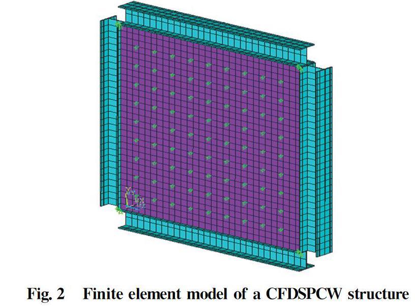
2.2 Description of finite element model
The finite element (FE) model of a CFDSPCW structure is shown in Fig.2. All the elements used are part of the ANSYS software. The concrete is modeled using the solid element SOLID65. The constitutive model of the concrete in the Code for Concrete Structure Design (GB 50010-2010) is used in this paper. Steel plates were modeled using the SHELL181 element. The ideal elastic-plastic model was used for the constitutive model of steel plates. The SOLID45 element was used for the frame beams and columns.
The formula for the shear-slip of shear stud connectors[17] is given by the Eq. (1).
where Vu is the ultimate shear capacity of the shear stud connectors, S is the relative slip of shear stud connectors and concrete; m and n represent the curve-fitted parameters, which are related to the dimensions of the shear wall. Based on the given formula for the shear-slip of shear connectors[17] and the push-out tests of stud shear connectors[18-19], the shear-slip relationship parameters of stud shear connectors can be curve-fitted.
The nonlinear spring element COMBIN39 is used for modeling the shear stud connectors[20]. The spring stiffness is calculated by the nonlinear shear-slip relationship given by Eq. (1). A contact element is used for the interaction between the concrete plate and the steel plate. CONTA173 is used for the internal surface of the steel plates, and TARGE170 is used for the external surface of the concrete plate; these elements are paired to represent the interface between the steel plate and the concrete plate. The contact surfaces are assumed to be smooth and without the inter-penetration of concrete and steel. The concrete plate and the steel plate transfer normal pressure to each other, but the normal tensile force is not considered.
The lateral load is applied with displacement-control. The largest lateral displacement is limited to 1/50 times that of the inter-story drift angle. At the same time, the initial elastic lateral stiffness K0 is set as the slope at the origin point of the load-displacement curve.
2.3 Finite element analysis
The finite element analysis consisted of three steps. First, an FE model of a CFDSPCW without any initial geometrical imperfections was constructed and applied with displacement constraints.
Second, because of the effects of processing, transportation, installation and other factors, steel plates in practical engineering applications will inevitably have some initial deformation and initial defect. The unit force F was applied in the FE model of the CFDSPCW. From the buckling eigenvalue analysis, the first buckling mode of the CFDSPCW was obtained and used for generating the initial geometrical imperfections, which should be considered to demonstrate the out-of-plane buckling and the geometric nonlinearity of the steel plates. According to the requirement of flatness of a concrete plate in a steel-concrete composite shear wall structure, the maximum amplitude of the initial defects of the steel plate is Lmax/1 000 (Lmax is the length of the longer edge of a steel plate)[21].
Third, an FE model of a CFDSPCW with its initial geometrical imperfections was constructed. The displacement constraints and the lateral displacement were applied to the FE model considering any large deformations, material nonlinearity and/or geometric nonlinearity. To calculate the ultimate shear capacity of the CFDSPCW, the equilibrium path of the load and displacement was traced using the arc-length method.
2.4 Validation of numerical model
A quasi-static seismic experiment of a CFDSPCW structure with stud connections was reported in the literature [9]. The dimensions of the composite shear wall in the test are shown in Fig.3. The section dimension of the two concrete-filled steel tubular columns (including the steel tubes) was 100 mm×120 mm. The sectional dimensions of the composite wall (including the steel plates) was 600 mm×90 mm. The concrete plate and the steel plates were connected with stud connectors at an interval of 100 mm. The thicknesses of the steel plates and steel tubes were 3 mm. The yield strength of the steel is 360 MPa. The cubic compressive strength of concrete was 27.5 MPa.
To validate the FE model of the CFDSPCW structure, the results of numerical analysis were compared with the experimental results as shown in Fig.4; this shows that the numerical results are almost the same as the experimental results at the linear elastic stage. With the increasing of the displacement, the load-displacement curve of the numerical analysis deviated from the experimental curve; but both of the curves show the same trend and are very close to each other in terms of ultimate shear resistance. The experimental and numerical resistance was 1 015.5 kN and 997.6 kN, respectively, and the latter is approximately 98% of the former. Therefore, this FE model of the CFDSPCW structure was extended for use in parametric studies.
3 Shear mechanism of composite walls
Based on the experimental and numerical results of the CFDSPCW under shear with different shear connectors, the shear mechanisms were identified and mechanical-based formulae were derived to calculate the ultimate shear capacity. Basically, the proposed formulae are all based on the cross-diagonal strut and tie model, i.e., the concrete forming diagonal compression struts between cracks and steel plates contributing diagonal tension ties. Moreover, the concrete cracked in the diagonal direction, and the diagonal tension yielding was perpendicular to the cracks[10-15]. As a result, the shear capacity was simply contributed by steel tension and concrete compression. The major difference is the formula of concrete compression in the following four models. To determine the critical parameters related to the shear capacity, and to compare the numerical results with the analytical results, four formulae are listed as follows:
1)The contribution of the concrete core to the shear bearing capacity of CFDSPCWs is considered in two ways: the nominal shear acting at the section along the span direction, and the diagonal compression strut[10]. This can be written as
2)In addition to Eq. (2), the effect of the concrete damage on the diagonal strut is considered[11]; this can be expressed as
3)The contribution of the concrete to the shear capacity is represented by a diagonal compression strut only, and the effect of shear-span to effective depth ratio is considered[12] as Eq. (4).
4)The formula used in Code for Design of Composite Structures (JGJ 138-2012)[22] and Technical Specification for Concrete Structures of Tall Buildings (JGJ 3-2010)[23] was based on the shear failure of steel plate-encased concrete composite shear walls and analogically modified for the shear capacity of CFDSPCWs under small shear-span ratios and zero axial loads[14], as shown below.
where fy is the yield strength of the steel plates; fcu and fc are the compressive strength of the standard concrete cube and prisms, respectively; θ is the angle of diagonal tension strips with respect to the horizon; As and Ac are the total cross section area of the steel plate and concrete core along the span, respectively; and λ is the shear-span ratio of the wall.
In accordance with the above-mentioned shear mechanism, the critical parameters for the shear resistance of CFDSPCWs includes the mechanical and geometric properties of concrete and steel plates. Therefore, the strength of the concrete, the thickness of the steel plate and the concrete plate, and the height-width ratio of the wall are used for parametric studies. It should be noted that the height-width ratio is similar to the shear-span ratio of walls, but the former is always a little bit smaller. In addition, the interval between the stud connectors is a critical parameter that ensures the composite effect of the CFDSPCW, and thus is used for parametric study as well.
4 Parametric analysis of the shear resistance of CFDSPCWs
Parametric analyses were performed to investigate the effects of several critical parameters on the shear resistance of CFDSPCWs, which included the interval between the stud connectors, the thickness of the steel plate and the concrete plate, the strength of the concrete and the height-width ratio of the wall on the shear performance of CFDSPCWs.
4.1 Effect of the interval between stud shear connectors
Specimens W0, W21 and W22 in Table 1 were used to study the effect of the interval between the stud connectors (ds) on the shear resistance of CFDSPCWs, and the interval changed from 200 mm to 600 mm.
Fig.5(a) shows the load-displacement curves of CFDSPCWs. The curves are the same at the elastic stage, indicating that the interval between the stud connectors had only a minor effect on the initial elastic stiffness of the CFDSPCWs. When ds was smaller than 300 mm, the load-displacement curves have no obvious softening part. The capacity of CFDSPCWs slightly increases with increasing displacement and changes to the plastic stage smoothly. However, when ds was equal to 600 mm, the curve slightly softens after the ultimate capacity.
Fig.5 (b) shows the shear stress-angle curves of the steel plates, in which the angle equals the ratio of the applied lateral displacement and the wall height. The steel plates can reach the shear strength (=235/3) no matter what the interval between the stud connectors is. But when ds is equal to 600 mm, the shear stress-angle curve obviously softens after the shear yielding of the steel plates. Out-of-plane buckling of the steel plates occurs at the maximum lateral displacement of 54 mm because the interval between the stud connectors is too large to restrain the steel plates, as shown in Fig.6(a). When ds is smaller than 300 mm, the shear stress-angle curves do not differ much after the shear yielding of the steel plates. The maximum out-of-plane displacement of the steel plates is not larger than 1.1 mm, as shown in Fig.6(b), suggesting that when ds is not larger than 300 mm, the out-of-plane buckling of the steel plates can be effectively prevented, and the whole steel plates are able to contribute to the shear resistance of CFDSPCWs.
4.2 Effect of the height-width ratio of the wall
Specimens W0, W11, W12, W13 and W14 in Table 1 were used to study the effect of the height-width ratio of the walls ?on the shear resistance of CFDSPCWs, in which??changes from 0.8 to 2.
Fig.7(a) shows that?significantly affects the initial elastic lateral stiffness K0 of CFDSPCWs. K0 approximately linearly decreases with an increase of β. Fig.7(b) shows that when β increased from 0.8 to 2 it resulted in the shear capacity decreasing by only 6.9% from 15.5 MN to 14.5 MN, indicating that the effect of the wall height-width ratio is insignificant. This is because the composite shear wall makes full use of the shear capacity of the steel plates and the concrete plate, and the lateral load is transferred through the whole cross section of a CFDSPCW.
4.3 Effect of the thickness of the steel plate
Specimens W0, W31, W32 and W33 in Table 1 were used to study the effect of the thickness of a steel plate (ts) on the shear resistance of CFDSPCWs, in which the plate's thickness changed from 6 mm to 20 mm.
Fig.8(a) shows that the load-displacement curves show no obvious softening, and the structure entered the plastic stage smoothly. With an increase of ts, the shear capacity of the CFDSPCW improves significantly. Fig.8(b) and (c) show that both the initial lateral stiffness and the shear capacity of the CFDSPCW increased linearly with the increase of ts.
4.4 Effect of the thicknesses of the concrete plate
Specimens W0, W41, W42 and W43 in Table 1 were used to study the effect of the thickness of a concrete plate (tc) on the shear resistance of CFDSPCWs, in which the thickness changed from 200 mm to 700 mm.
Fig.9(a) shows that the load-displacement curves display no obvious softening, and the structure entered the plastic stage smoothly due to the good composite effect of the concrete and steel plates. As tc increased, the shear capacity of the CFDSPCWs improved significantly. Moreover, Fig.9(b) and (c) demonstrate that both the initial lateral stiffness and the shear capacity increased linearly with an increase of tc. In CFDSPCWs, the concrete plate between the steel plates bears the lateral load and provides lateral stiffness, and also prevents the out-of-plane buckling of the steel plates. However, after taking the weight and the space of the structure into consideration, the thickness of concrete plate should not be too large.
4.5 Effect of the strength of the concrete
Specimens W0, W51, W52, W53 and W54 in Table 1 were used to study the effect of the strength of the concrete (fcuk) on the shear resistance of the CFDSPCWs in which the strength changed from 20 MPa to 80 MPa.
Fig.10(a) shows that the initial elastic lateral stiffness at the elastic stage gradually increased as the strength of the concrete increased. Fig.10(b) shows that the shear capacity of the CFDSPCWs rises linearly as the strength of the concrete increases. Furthermore, the higher strength of concrete can reduce the wall's weight and requires less space for the structure. As a result, the shear capacity of CFDSPCWs could be improved by using high strength concrete, especially for high-rise buildings.
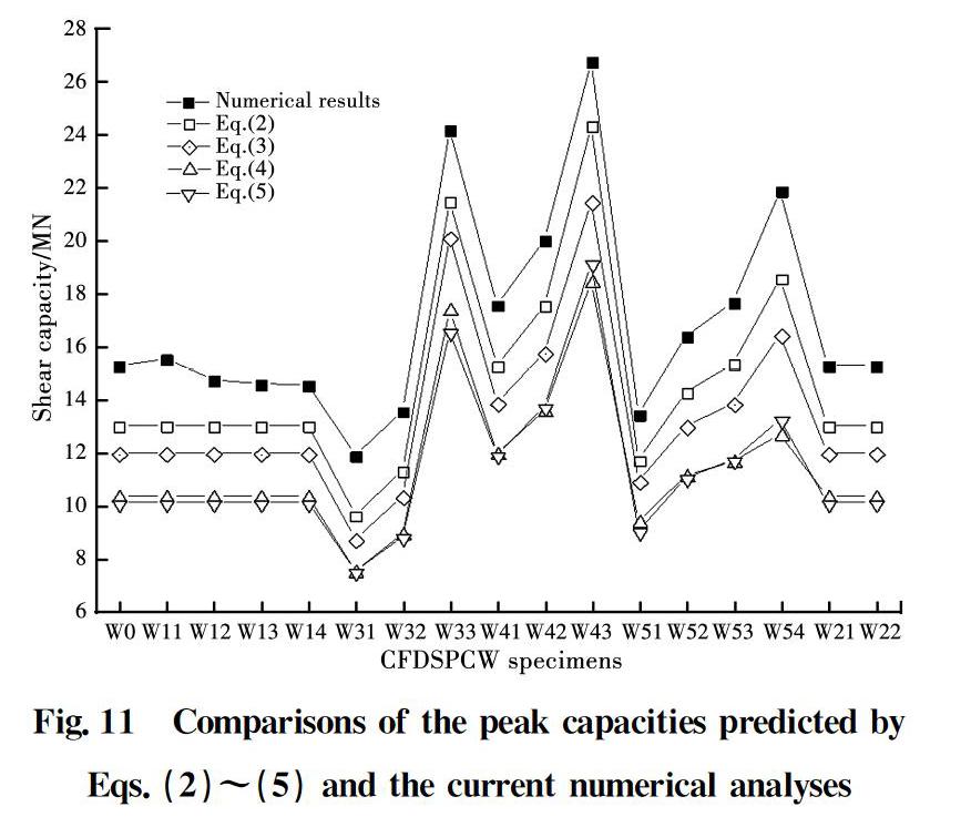
4.6 Comparisons of numerical and analytical results
Fig.11 shows the comparisons of the peak capacities predicted by Eqs.(2)~(5) and the current numerical analysis. Clearly, the numerical results reasonably agree with the predicted results in terms of the effects of different parameters; and the relative errors between the numerical results and, for example, Eq.(2), are about 9%-19%. Therefore, the numerical results are generally larger, indicating that the results of Eqs.(2)~(5) are on the safe side.
5 Conclusions
This paper presents the results of extensive studies of the shear resistance of CFDSPCWs. Based on the relevant parametric analyses, the conclusions are as stated below:
1) The interval between the stud connectors significantly affected the shear performance of the CFDSPCWs. Intervals between stud connectors that were not larger than 300 mm were able to effectively prevent the plates from out-of-plane buckling, and prevent the degradation of the shear capacity of the CFDSPCWs.
2) In accordance with the assumption that the frame beams and columns surrounding CFDSPCWs are hinge connected and are rigid, the height-width ratio of the wall had a notable effect on the initial elastic stiffness, and aminor effect on the shear capacity of the CFDSPCWs.
3) The shear resistance of CFDSPCWs can be improved by increasing the thickness of the steel and the concrete plate and the strength of the concrete. But, after taking the weight and the space of the structure into consideration, the thickness of the concrete plate should not be too large.
Acknowledgements
The authors are grateful for support from the National Natural Science Foundation of China(Grant No.51608168), the Fundamental Research Funds for the Central Universities (No. 2017B16014; 2019B12814).
References:
[1] LI G Q. Design of multi-storey and high-rise steel structure [M]. Beijing: China Architecture and Building Press, 2003.
[2] WANG M, CAO W L, ZHANG J W. Seismic research and development of composite shear wall [J]. Earthquake Engineering and Engineering Vibration, 2007, 27(5): 80-87.
[3] HAO K C, GAO H, SUN F F. Progress in seismic performance of composite steel plate shear walls [J]. Progress in Steel Building Structures, 2010, 12(2): 49-56.
[4] PRYER J W, BOWERMAN H G. The development and use of British Steel Bi-Steel [C] // Proceedings of the Eighth International Offshore and Polar Engineering Conference, Montreal, Canada, 1998: 173-178.
[5] NIE J G, TAO M X, FAN J S.Research advances of composite shear walls with double steel plates and filled concrete [J]. Building Structure, 2011, 41(12): 52-60.
[6] ZHU W J, MA J, HUANG H P.Research and application of the Bi-steel plate shear wall in special structure [J]. Special Structure, 2010, 27(2): 14-16.
[7] CHEN J S, ZHANG J. Construction technology of composite structure of double steel plate and shear wall in Yancheng broadcast television tower [J]. Construction Technology, 2011, 40(15): 17-20.
[8] MOY S S J, XIAO R Y, LILLISTONE D. Tests for British steel on the shear strength of the studs used in the Bi-steel system [R]. University of Southampton, 1998.
[9] NIE J G, BU F M, FAN J S. Experimental research on seismic behavior of low shear-span ratio composite shear wall with double steel plates and infill concrete [J]. Journal of Building Structures, 2011, 32(11): 74-81.
[10] WEI F F, ZHA B, ZHAO H B, et al. Shear resistance performance of steel-concrete-steel composite shear wall [J]. Journal of Southeast University (English Edition), 2012, 28(1): 73-78.
[11] ZHU X R, ZHAO B C, ZHAO S Q, et al. Research on shear behavior of steel frames with bi-steel-plate composite shear wall infilled concrete [J]. Journal of Suzhou University of Science and Technology (Engineering and Technology), 2015, 28(2): 31-35. (in Chinese)
[12] GUO Q Q, HUANG Z Y, ZHAO W Y, et al. Calculation method for shear bearing capacity of steel-concrete composite shear wall [J]. Journal of Building Structures, 2015, 36(6): 145-150. (in Chinese)
[13] JI X D, JIA X F, QIAN J R. Experimental study on shear behavior of steel-plate composite shear walls [J]. Journal of Building Structures, 2015, 36(11): 46-55. (in Chinese)
[14] XIONG F, HE T, ZHOU N. Study on shear strength of double-steel concrete shear wall of nuclear power plant [J]. Journal of Hunan University (Natural Science Edition), 2015,42(9): 33-41.
[15] ZHANG Y J, LI X J, ZHANG T, et al. In-plane shear performance of double-steel concrete composite wall: the oretical analysis and numerical simulation[J]. Journal of Applied Basic and Engineering Science, 2017, 25(5): 945-955. (in Chinese)
[16] GUO Y L, ZHOU M, DONG Q L. Research of elastic-plastic shear limit bearing capacity and hysteretic behavior on buckling-resisting steel plate shear wall [J]. Engineering Mechanics, 2009, 26(2): 108-114.
[17] CLUBLEY S K, MOY S S J, XIAO R Y. Shear strength of steel-concrete-steel composite panels. Part I: testing and numerical modelling [J]. Journal of Constructional Steel Research, 2003, 59(6): 781-794.
[18] CLUBLEY S K, MOY S S J, XIAO R Y. Shear strength of steel-concrete-steel composite panels. Part II: detailed numerical modelling of performance [J]. Journal of Constructional Steel Research, 2003, 59(6): 795-808.
[19] NIE J G. Composite structures of steel and concrete [M]. Beijing: China Architecture and Building Press, 2005.
[20] YANG Y. Study on the basic theory and its application of bond-slip between steel shape and concrete in SRC structures [D]. Xi'an: Xi'an University of Architecture and Technology, 2003.
[21] Code for acceptance of constructional quality of concrete structures: GB 50204-1992 [S]. Beijing: Ministry of Construction of Peoples' Republic of China, 1992.
[22] Code for design of composite structure: JGJ 138-2012 [S]. Beijing: China Architecture and Building Press, 2012.
[23] Technical specification for concrete structures of tall buildings: JGJ3-2010 [S]. Beijing: China Architecture and Building Press, 2010.
(編輯 胡英奎)
