Dual-function beam splitter of high contrast gratings?
2021-05-06 08:54:52WenJingFang房文敬XinYeFan范鑫燁HuiJuanNiu牛慧娟XiaZhang張霞HengYingXu許恒迎andChengLinBai白成林
Chinese Physics B 2021年4期
Wen-Jing Fang(房文敬), Xin-Ye Fan(范鑫燁), Hui-Juan Niu(牛慧娟),2,Xia Zhang(張霞), Heng-Ying Xu(許恒迎), and Cheng-Lin Bai(白成林),?
1Shandong Provincial Key Laboratory of Optical Communication Science and Technology,School of Physical Science and Information Engineering,Liaocheng University,Liaocheng 252000,China
2Institute of Information Photonics and Optical Communications,Beijing University of Posts and Telecommunications(BUPT);State Key Laboratory of Information Photonics and Optical Communications,Beijing 100876,China
Keywords: beam splitter,high contrast gratings,polarization-selective,focusing,phase modulation
1. Introduction
Beam splitters are vital devices for many processes mainly in optical information processing,holography,and numerous other applications.[1–3]Splitters that are composed of multilayer coatings, fused fibers, and slot waveguides, are widely used, but there are significant optical losses due to the presence of the imaginary part of the refractive index and complicated fabrication procedures. Recently, photonic crystal (PhC) splitters[4,5]or metasurface-based splitters[6]have been available, most of which take advantages of the complementary metal–oxide semiconductor (CMOS) compatibility and strong optical confinement of the silicon-on-insulator(SOI) wafer, and have benefits of compact structures. However, their output light is not spatial light, and it is difficult to integrate with large area semiconductor laser array or photodetector array in a vertical coupling.[7,8]There is another more compact device, called high-contrast gratings (HCGs),which can function as high efficiency gratings,[9,10]high extinction ratio polarizing beam splitters (PBS),[11–13]broadband reflectors,[14–16]lens,[17,18]and beam splitters,[19,20]because of the high contrast between the refractive indices of the gratings and the surrounding material.
So far, beam splitters made of pure dielectric gratings have attracted a lot of attention due to their merits of compact structure, low energy loss, high efficiency, and stable performance. Wang et al. presented a double-layer reflective grating 1×3 beam splitter with a covering layer at a wavelength of 1550 nm.[21]After that, Gao et al. presented a single-groove grating for five-port transverse electric (TE)polarization(the E-field vector is parallel to the grating bars)beam splitting under normal incidence at a wavelength of 1550 nm.[22]Of course, there are other beam splitters based on grating,such as T-shaped grating,[23]embedded grating,[24]double-groove grating,[25]metal-mirror-based grating,[26,27]three-layer grating,[28]etc.In the following,we will show that the grating can be designed as a beam splitter and fabricated efficiently by a simple structure with using the complementary metal–oxide semiconductor(CMOS)compatibility and strong optical confinement of the SOI wafer. Furthermore, these polarization-selective devices can be applied to some specific polarization-sensitive systems.
Generally, most of reported subwavelength gratings are single function devices.[29,30]If two different functions can be fulfilled by using only one grating,this will be interesting for practical applications. We design and successfully fabricate a dual-function HCG that can be used as a four-port beam splitter for transverse magnetic(TM)polarization(the E-field vector is perpendicular to the grating bars) and as a device with high focusing efficiency. Firstly, a 1×4 beam splitter is designed by the RCWA method,then its excellent performances are simulated by the finite element method(FEM).Finally,the fabrication and characterization of splitters realized on an SOI wafer are presented and discussed.
2. Methods
Polarization-selective focusing lens and focusing reflector using HCGs have been reported in Refs. [31,32] respectively. Both of them have sub-wavelength structures,of which the grating bars and surrounding media have a big refractive index difference. Only zeroth-order diffraction light can be propagated to the far field due to the period of the HCGs which is shorter than the wavelength of incident light, while other high-order diffraction light becomes evanescent waves.So it is possible to concentrate almost all the energy of the incident light on the zeroth-order reflection light by using the HCGs.[33]This phenomenon was then explained as the interference of the internal propagation modes in the input plane and output plane.[34]It can also beexplained as leaky-mode resonance.[35]
A similar design philosophy is employed in this study,the schematic diagram of a 1×4 beam splitter based on HCGs is shown in Fig.1, the HCGs consist of a 320-nm silicon layer that is surrounded by air and a 500-nm buried oxide layer as a low index medium. Let s(the product of period Λ and duty cycle η) denote the width of the grating bar, and Λ refers to the grating period, while they are randomly selected and not the same. And let tgdenote the grating thickness and tlrefer to the height of the buried oxide layer. The parameters mentioned above are all constants in this work. The refractive indices of silicon(Si)and silicon dioxide(SiO2)are 3.47 and 1.47 respectively.
As shown in Fig.1, the reflected light in each subregion will converge into a focusing beam,thus the incident light will be split into four beams.
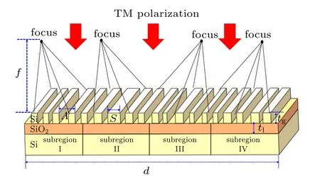
Fig.1. Schematic diagram of investigated 1×4 beam splitter.
2.1. Grating design
The design procedures of a polarization-selective focusing lens based on HCGs have been reported in the relevant work[31]which indicates that the aperiodic grating achieving the focusing function or other performance depends on the phase profile of the wave front, and that the local phase depends only on the local geometry of the grating bars around that focusing region. So to design an HCGs beam splitter that has a focusing function, the key step is to select grating units that can achieve particular phase profiles on reflected plane while maintaining high reflectivity. Initially, reflectance and wave front phase of the reflected light for periodic HCGs are numerically calculated based on the RCWA method[36,37]under normal incidence at a wavelength of 1550 nm with TM polarization. The simulation results showing the reflectivity and phase shift in reflection as a function of the grating period Λ and duty cycle η,are reported in Fig.2. Later,an important step is to find out the optimal structural parameters sets (Λn,ηn) with a high reflectivity (such as |r|2>95%) as shown in Fig.2(a), and the corresponding phase of the reflected light that should cover a full 2π range of variation within the high reflectivity region as shown in Fig.2(b). Lower limit of the reflectivity in a full 2π range must be reduced so that the whole phase spectrum is continuous, which all the phases could be selected from. So by carefully selecting grating structure parameters, we can get focusing in each subregion where the introducing phase profile adapts to Eq. (1). In summary, this process can be realized by searching for the reflectivity and phase look-up table as shown in Fig.2.
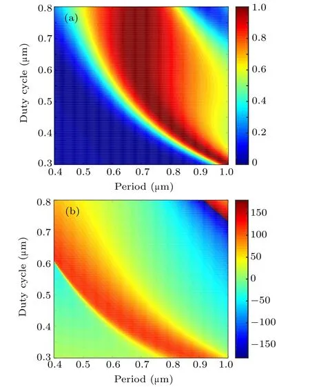
Fig.2. Simulated (a) reflectivity and (b) phase of the reflection coefficient for a family of periodic HCG with TM polarization.
A similar approach in the study of polarization-selective focusing lens is applied to designing a 1×4 beam splitter. Because the bar size of the grating will affect the state of the magnetic resonance and determine the phase profile of the reflected light,we should set the bars with different geometries reasonably to achieve the focusing function in each subregion.By analyzing the reflected light wave front,the desired phase profile is parabolic in each subregion. As shown in Fig.3,the solid line represents the ideal phase distribution for an aperiodic HCG calculated by Eq. (1), the different colored dots represent the designed discrete phases corresponding to (Λn,ηn),which specify the widths and positions of each bar in the HCGs.The reflected light will be focused on four beams when the phase shift distribution of the reflected light meets Fig.3.

where Φ(x)is the local phase of the reflected light wave front in the reflection plane, λ and Φ0refer to the wavelength of incident light and original phase,and f and d denote the focal length and the length of the HCGs as shown in Fig.1.
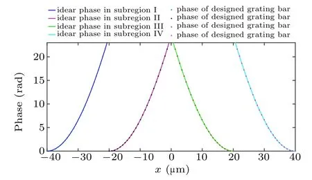
Fig.3. Phase distributions, with solid line denoting ideal phase profiles in different subregions,and points referring to designed phase distribution.
2.2. Simulation and analysis
From the RCWA simulation results,assuming that the local phase response depends on the local structural parameters,the total phase shift provided by the designed structure should be ?Φ,The structure width is d,the equivalent focal length f is given by[38]
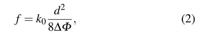
the relation among the design parameters ?Φ, d, the wavelength λ,and the focal length f of the aperiodic HCG will be useful in designing the HCGs that have to fulfill a certain set of requirements.
On the basis of the design process mentioned above,we design an aperiodic HCG beam splitter with a width of 60.32μm. For the current grating design,the total phase shift is 23.48 rad in each subregion and the focal length for each of four focusing beams is estimated at 25 μm. The performance of the designed HCG beam splitter is evaluated by the finite element method (FEM)[39]with TM polarization at a wavelength of 1550 nm. The simulation domain is depicted in Fig.4(a). A perfectly matched layer(PML)is used to model an open boundary as it completely absorbs any incident wave with very low, ideally zero, transmission, and the scattering boundary condition is used to avoid the reflection interference.
The simulation results are plotted in Figs. 4(b)–4(c).Specifically, figure 4(b) shows the E-field distribution. The distance between reflection plane and beam-located plane is recorded to be 25.1μm, which is close to the designed value of 25μm. The total reflectance of the splitter is derived to be 92.48%. According to the theoretical Airy disk diameter,[40]the four focusing beams have power efficiencies of 23.04%,23.23%, 23.11%, and 22.7% respectively, which are lower than the total power efficiency of 92.48%% due to the wave front sampling. Figure 4(c)shows the E-field intensity in the x direction of the reflection plane at a distance of 25.1μm which corresponds to the focusing beam as shown in Fig.4(b).
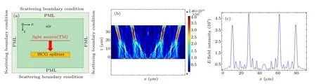
Fig.4. (a)Schematic diagram of simulation domain,(b)normalized electric field intensity distribution for HCG beam splitter,and(c)E-field intensity in x direction.
3. Experimental results and discussion
The 1×4 beam splitter based on HCGs with a focal length of 150 μm and a distance of 100 μm between each beams is fabricated on an SOI wafer.The overall beam splitter footprint is ~0.25 mm2. The production process mainly includes electron beam lithography(EBL)and inductively coupled-plasma(ICP)etching. The optical microscope image of the fabricated 1×4 beam splitters is indicated in Fig.5; from the scanning electron microscope(SEM)images of the local HCGs, it can be seen that some narrow grating bars are shaped into cylinders due to the excessive lateral etching and the difference in color of the optical microscope image, caused by the phase shift.
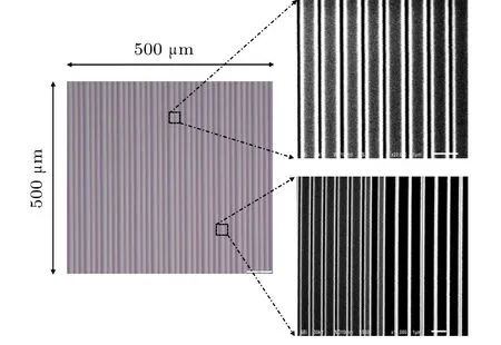
Fig.5. Optical microscope image and SEM images at various locations of fabricated HCGs beam splitter.
After fabrication, the optical properties of beam splitter are tested and characterized. Figure 6 shows the experimental setup for measurement. The sample is illuminated normally from the surface of the HCG wafer by a tunable laser(1480 nm< λ < 1610 nm) with a wavelength of 1550 nm.Since it measures reflected light, an isolator is used to protect the laser from being damaged by reflected light. A fiber collimator connected to the single-mode fiber is used to output a 400-μm diameter uniform beam that overfills the HCGs,approximately matching the size of the HCGs,and TM polarization can be realized by a polarization controller(PC).Here,a cube beam-splitter is used to receive the reflected light from the grating,which can split the transmitted light and reflected light into 1:1. Finally,the characteristics of the reflected beam are recorded by the beam quality analyzer.
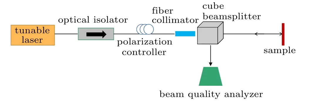
Fig.6. Experimental setup for measurement.
The results at a distance of 160 μm between the reflection surface of the HCGs and CCD are summarized in Fig.7.Specifically,figure 7(a)shows the intensity distribution of the HCGs beam splitter; it is obvious to see that the beam can be split and focused on four different beams. The values of full width at half maximum(FWHM)of these beams are calculated to be about 121.53 μm, 117.38 μm, 118.73 μm, and 122.16 μm respectively. Figures 7(b) and 7(c) show threedimensional intensity distribution and the curve of intensity distribution. From the two figures, the intensity ratio among the four beams is 0.82:1:0.91:0.85, which is in power equalization approximately and the distance between the beams in the x direction is about 95.51μm, 146.27μm, and 96.42μm respectively, which corresponds to the scenario Fig.4(c). By calculation,the results of Fig.4(c)are very close to those from the designed power beam splitter with a focal length of 150μm and a distance of 100μm between the adjacent beams.Finally,the total reflectivity is measured to be 64.6%. The beam profile is not exactly Gaussian,and difference between theoretical values and the measurements may be caused by the aperiod of the gratings and some other uncertainty introduced by the setup, or the inaccuracy of the focal plane measured. Moreover, the loss is attributed to the transmission from substrate backside interface and the scattering by the random roughness of the etched silicon bars.
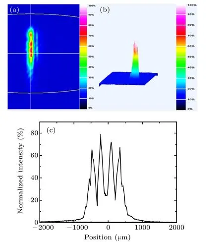
Fig.7. Experimental results, showing (a) two-dimensional intensity distribution, (b) three-dimensional intensity distribution, and (c) normalized intensity distribution.
4. Conclusions
An aperiodic HCGs’ polarization-selective beam splitter based on SOI has been demonstrated in this study.We initially propose the simple analytical expressions for the HCGs as a beam splitter,which can provide helpful guidelines for future grating designs. With an optimal grating period and phase distribution,the grating exhibits an excellent beam splitter under normal incidence. Experimental results show that when the distance of 160μm between the reflection surface of the HCGs and CCD, the intensity of ratio of the four beams of output beam under TM polarization at 1550 nm is 0.82:1:0.91:0.85,and the distance between the adjacent beams is 95.51 μm,146.27 μm, and 96.42 μm respectively in the x direction,which is in reasonable agreement with the theoretical values.This novel beam splitter can be incorporated into a variety of integrated photonic platforms. Since the SOI wafer can offer a high refractive index contrast suitable for the fabrication of HCGs,a high-efficiency beam splitter based on HCGs will be a useful device for future practical applications.
- Chinese Physics B的其它文章
- Quantum annealing for semi-supervised learning
- Taking tomographic measurements for photonic qubits 88 ns before they are created*
- First principles study of behavior of helium at Fe(110)–graphene interface?
- Instability of single-walled carbon nanotubes conveying Jeffrey fluid?
- Relationship between manifold smoothness and adversarial vulnerability in deep learning with local errors?
- Weak-focused acoustic vortex generated by a focused ring array of planar transducers and its application in large-scale rotational object manipulation?