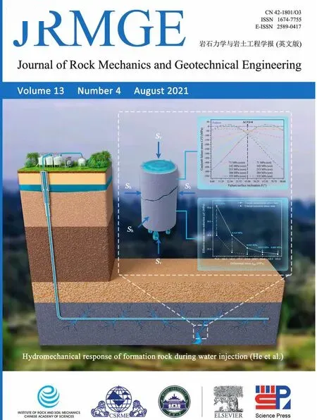
Hydromechanical behaviors of andesite under different stress states during fluid injection
2021-07-27 10:00:06MiaoHeQiLiXiayingLiLiangXuMichaelhn
Miao He, Qi Li,*, Xiaying Li, Liang Xu, Michael Kühn
a State Key Laboratory of Geomechanics and Geotechnical Engineering,Institute of Rock and Soil Mechanics,Chinese Academy of Sciences, Wuhan,430071,China
b University of Chinese Academy of Sciences, Beijing,100049, China
c Fluid Systems Modelling Section, GFZ German Research Centre for Geosciences, Potsdam, Germany
d Institute of Earth and Environmental Science, University of Potsdam, Potsdam, Germany
Keywords:Water reinjection Stress state Hydromechanical (HM) coupling Injection-induced seismicity Numerical modeling
ABSTRACT Water reinjection into the formation is an indispensable operation in many energy engineering practices.This operation involves a complex hydromechanical (HM) coupling process and sometimes even causes unpredictable disasters, such as induced seismicity. It is acknowledged that the relative magnitude and direction of the principal stresses significantly influence the HM behaviors of rocks during injection.However, due to the limitations of current testing techniques, it is still difficult to comprehensively conduct laboratory injection tests under various stress conditions, such as in triaxial extension stress states. To this end, a numerical study of HM changes in rocks during injection under different stress states is conducted. In this model, the saturated rock is first loaded to the target stress state under drainage conditions, and then the stress state is maintained and water is injected from the top to simulate the formation injection operation.Particular attention is given to the difference in HM changes under triaxial compression and extension stresses. This includes the differences in the pore pressure propagation, mean effective stress, volumetric strain, and stress-induced permeability. The numerical results demonstrate that the differential stress will significantly affect the HM behaviors of rocks,but the degree of influence is different under the two triaxial stress states.The HM changes caused by the triaxial compression stress states are generally greater than those of extension,but the differences decrease with increasing differential stress,indicating that the increase in the differential stress will weaken the impact of the stress state on the HM response. In addition, the shear failure potential of fracture planes with various inclination angles is analyzed and summarized under different stress states. It is recommended that engineers could design suitable injection schemes according to different tectonic stress fields versus fault occurrence to reduce the risk of injection-induced seismicity.
1. Introduction
Most industrial activities associated with energy engineering are accompanied by the process of reinjecting formation water or industrial wastewater into deep permeable brine aquifers, where the rock is almost saturated,such as hydraulic fracturing(Guo et al.,2014; Vengosh et al., 2014; Diaz et al., 2020), oil and gas exploitation (Spencer,1989; Sun et al., 2018; Wan and Liu, 2018),enhanced geothermal systems (EGSs) (McClure and Horne, 2014;Olasolo et al., 2016; Gong et al., 2020), and CO2geological sequestration(Xu et al.,2019;Rathnaweera and Ranjith,2020;Wang et al.,2020a).The purposes of water reinjection are,on the one hand,to protect the surrounding environment and prevent the pollution of shallow groundwater or land destruction by wastewater(Hatzenbuhler and Centner, 2012; Warner et al.,2013), and on the other hand, to partially compensate for a production-related drop in formation pressure,thereby avoiding a net increase in formation pressure (Haddad and Eichhubl, 2020). It has been well accepted that the original stress field of the formation can be changed by water reinjection. The injection of a large amount of fluid will significantly increase pore pressure in the formation,resulting in a reduction in effective stress (Zheng et al., 2015). Generally, the insitu stress state of the formation is critical for injection activity. A favorable stress state can ensure the safety and efficiency of production, while a poor stress state may greatly hinder production and even induce disasters such as earthquakes, especially when there are hidden fractures or faults in the formation. For example,the Pohang earthquake with moment magnitude MW=5.5 in 2017,which caused a loss of more than$75 million USD,has been shown to be induced by the pore pressure of high-pressure injected fluid activating a previously unmapped fault under a critical stress state(Ellsworth et al., 2019; Lee et al., 2019; Woo et al., 2019).
Notably, the most relevant role in causing an induced earthquake is played by fault orientation versus dominant stress orientation (Lei et al., 2020). Anderson (1951) proposed three tectonic stress states corresponding to different fault types based on the direction and relative magnitude of initial stresses when the fault was formed, i.e. the normal faulting stress state (Sv= σ1>SHmax= σ2> Shmin= σ3), the reverse faulting stress state(SHmax= σ1> Shmin= σ2> Sv= σ3) and the strike-slip faulting stress state(SHmax=σ1>Sv=σ2>Shmin=σ3),where Sv,SHmaxand Shminare the vertical in situ stress(Pa),the maximum horizontal in situ stress (Pa) and the minimum horizontal in situ stress (Pa),respectively; and σ1, σ2and σ3represent the maximum, intermediate and minimum principal stresses (Pa), respectively. How to choose an appropriate injection strategy is closely related to the complex hydromechanical (HM) coupling process under different stress states.
Laboratory rock testing can provide useful insights for understanding complex geophysical processes (Wang et al., 2020b; Li et al., 2021). At the laboratory scale, the conventional triaxial test is widely used to study the mechanical characteristics of rocks and can reflect the influence of differential stress (or deviatoric stress field). Commonly used conventional triaxial tests can be divided into triaxial compression tests and triaxial extension tests due to the different directions of the major and minor principal stresses(Ignat et al.,2019).Different loading modes correspond to different tectonic stress states of the formation,as shown in Fig.1,which will significantly affect the experimental results.
To simulate the formation injection operation more realistically,it is necessary to carry out rock injection tests in the laboratory.Obviously, the injection test has more stringent requirements on rock properties, equipment and experimental conditions than the single mechanical tests. The triaxial compression test is the most widely used method and has accumulated a large amount of available test data. Recently, Nicolas et al. (2020) conducted fluid injection tests on low-porosity andesitic rock under triaxial compression stress to investigate the pore pressure migration law and rock HM behavior under a differential stress of 356 MPa.Ji et al.(2020) and Ji and Wu (2020) implemented a series of injectiondriven shear tests under the triaxial compression stress state to study the development of pore pressure heterogeneity in rock fractures and its influence on fracture instabilities. Unfortunately,to the authors’ knowledge, there are currently few laboratory injection tests under triaxial extension stress conditions, probably due to the operational difficulty and high requirements for experimental equipment (Zoback, 2010). Only some experiments to determine rock permeability under a triaxial extension stress state have been reported(Zoback and Byerle,1976;Zhu et al.,1997;Popp et al.,2001;Xing et al.,2013).However,the permeability test does not involve the injection of large amounts of fluid, which cannot reflect the dynamic diffusion process of pore pressure during injection and is quite different from the actual formation injection process. Whether there is a difference in the hydromechanical behaviors of rocks under triaxial compression and extension stress states during injection remains to be addressed.

Fig.1. Field-scale tectonic stress state versus laboratory-scale conventional triaxial stress state: (a) Normal faulting stress state versus triaxial compression stress state; and (b)Reverse faulting stress state versus triaxial extension stress state.
HM coupling is fundamental knowledge underlying the physical process of water reinjection into the formation, which can be described by various numerical simulation methods(Rutqvist et al.,2016;Rathnaweera et al.,2020).Different from hydraulic fracturing or other technologies to reconstruct reservoirs,water reinjection is not designed to increase production and does not pay attention to either hydraulically induced rock failure or fracture development for improving permeability.Therefore,it is reasonable and feasible to use the finite element method (FEM) to simulate this process,which has advantages in solving continuous medium problems. In this study, simulations with FEM were used to investigate the HM behavior and the shear failure potential for rock under different stress states during injection in terms of the coupling mechanisms.The general governing equations of the HM coupling model were first derived. Then, according to experimental data obtained from the literature,HM coupled models corresponding to different stress states were established, including the hydrostatic stress state,triaxial compression stress state and triaxial extension stress state.The validity of the numerical model was verified by hydrostatic test results from Nicolas et al. (2020). Finally, the numerical results under different stress states were presented and discussed.
2. General governing equations
The FEM is used to analyze the coupled HM process of rock during fluid injection using the multiphysics coupling simulator COMSOL Multiphysics?. Here, the governing equations for the coupling mechanisms of poroelastic media are presented.
2.1. Coupled poroelastic flow model
In the COMSOL Multiphysics? platform, the fluid mass conservation of the linear elastic material can be expressed as (Li et al.,2009):

where φ is the effective porosity of the rock;ρfis the fluid density(kg/m3); αBis the Biot’s coefficient; εvis the injection-induced volumetric strain; Qmis the source term of mass (kg/(m3s)); and u is the Darcy’s velocity of the fluid (m/s), which is derived from Darcy’s law (Lapwood,1948; Whitaker,1986):

where k is the rock permeability (m2), η is the coefficient of dynamic viscosity of the fluid(Pa s),and Ppis the pore pressure(Pa).
The momentum conservation equation can be depicted as (Li et al., 2009):

where Fvis the body force vector(N);ρsis the rock density(kg/m3);Vsis the velocity of the solid(m/s);and σ′is the effective stress(Pa),which is related to the total stress σ, pore pressure Pp, and Biot’s coefficient αB, i.e. Terzaghi’s effective stress law (Hu and Rutqvist,2020) (with compression positive):

In the experiment,the strain can be measured directly,while the stress needs to be transformed by strain.The relationship between stress and strain can be expressed as (Rice and Cleary,1976):

where v0is the initial volume (m3); Δv is the volume increment(with tension positive) (m3);is the effective mean stress (Pa),which can be calculated as(with compression positive); and Ksis the drained bulk modulus (Pa),which can be calculated as (Delle Piane and Sarout, 2016; Wang et al., 2020c):

where Esis the Young’s modulus (Pa) and ν is the Poisson’s ratio.
2.2. Porosity and permeability models
Currently, there are various models of porosity and permeability.In this context,a porosity model related to effective stress is used (Rutqvist and Tsang, 2002; Rinaldi et al., 2015):

where φ0is the initial porosity, and φris the residual porosity.
The permeability dependent on porosity is expressed as(Rutqvist and Tsang, 2002; Rinaldi et al., 2015):

where k0is the initial permeability (m2).
3. Modeling hydromechanical behaviors of rocks under different stress states
3.1. Model description
Partial data from pore pressure pulse experiments of microcracked andesite under hydrostatic stresses according to Nicolas et al. (2020) were used to build a series of two-dimensional (2D)finite element axisymmetric models. In this experiment, a lowpermeability andesite of 100 mm in length and 50 mm in diameter was subjected to a pressure pulse to investigate the pore pressure distribution during injection recorded by fiber optic sensors. The sample was first saturated (initial pore pressure of approximately 0.2 MPa) and maintained under the hydrostatic confining pressure (40 MPa), and a pressure pulse maintained at 20 MPa was then injected from the sample top to the downstream dead volume composed of the tubing and the pump(see Fig.10 in Nicolas et al. (2020)).
Based on this experimental process, the simulation protocol presented herein involves the following two phases (Fig. 2a):
(1) Phase 1: Pre-injection phase. The core is saturated with deionized water and first subjected to a hydrostatic pressure of 40 MPa under drained conditions. Then, the loads are elevated to reach the target differential stress. The internal fluid pressure is uniformly distributed and kept constant at 0.2 MPa,but the stress state is varied.
(2) Phase 2: Injection phase. Under different stress states,deionized water is evenly injected downward from the top of the core at a controlled pressure of 20 MPa.During injection,water can flow from the bottom of the core into the downstream dead volume.To ensure that the hydraulic connection between the two ends of the rock is fully established, the injection pressure is first set to 0.2 MPa and is then increased to 20 MPa at 2.667 min after water injection. The pressure was maintained until the end of injection at 60 min.
The initial and boundary conditions of the model are consistent with the experiment,as shown in Fig.2b.The axial rotating faces of the model are no-flow boundaries, and the upstream and downstream boundary conditions satisfy following equations(Nicolas et al., 2020):

where t0is the start time of injection (min); z = 0 represents the bottom (downstream), and z = l represents the top (upstream);Pdownis the downstream pressure (MPa); A is the injection area(m2); and Sdis the storage capacity of downstream dead volumes(Pa-1),which can be calculated as Sd=Vd/Kf(Pimienta et al.,2016).The parameters used in the simulation are shown in Table 1.
Additionally, similar to Nicolas et al. (2020), three observation points (OP-1, OP-2 and OP-3) are placed at 3/4,1/2, and 1/4 of the height of the core to simulate fiber optic sensors.
3.2. Stress states
According to the classification pattern proposed by Anderson(1951), the hydrostatic stress state without differential stress and the triaxial stress state with differential stress are considered. The in situ stress, principal stress, and loading pressure corresponding to the three stress states are shown in Table 2. Note that Svand Share the vertical and horizontal in situ stresses, respectively; while Paxiand Pconare the axial and confining pressures,respectively.

Table 1 Parameters used in the model.

Table 2 Different stress states and corresponding loading modes.
To ensure no shear failure of the rock during loading, it is necessary to determine the limit value of differential stress,which can be obtained by the Coulomb failure criterion (Al-Ajmi and Zimmerman,2005; Shen et al., 2020):

where|τ|is the shear strength(Pa);C is the internal cohesion(Pa);and μsis the internal friction coefficient, which can be written as

where φ is the internal friction angle (°).
Assuming that the minimum principal stress σ3is known, the maximum principal stress σ1can be derived when the rock is in a critical stress state.As shown inFig.3,when the Mohr circle istangent to the failure envelope,the right-angle side of the shadow triangle is(σ1- σ3)/2, and the hypotenuse of the triangle is C/tanφ+(σ1+σ3)/2.Then,(σ1-σ3)/2 = [C/tanφ+(σ1+σ3)/2]sinφ can be derived by the trigonometry.Combined with Eq.(12),the maximum principal stress σ1under the critical stress state can be expressed as

Fig. 3. Schematic diagram of the critical stress state based on the Mohr-Coulomb criterion.

In our simulation, the σ3value is always fixed at 40 MPa;according to Eq. (13), σ1under the critical stress state is approximately 395.73 MPa, and the maximum differential stress σdiff= σ1-σ3is 355.73 MPa. Based on this, six different differential stresses are set, i.e. 0 MPa, 71 MPa, 142 MPa, 213 MPa,284 MPa, and 355 MPa, where 0 MPa corresponds to the hydrostatic stress state, and the others correspond to different triaxial stress states.
3.3. Basic assumption
To reduce unnecessary numerical calculations, the following basic assumptions were made before modeling:
(1) Note that in the experiment conducted by Nicolas et al.(2020), the sample remained within the elastic domain under the differential stress of 356 MPa (greater than the maximum differential stress set in the simulation);therefore,the rock is assumed to be a homogeneous, isotropic, and elastic porous medium in modeling.
(2) The experiment was carried out under quasi-static conditions,and the pressure pulse was constant,thus Qmin Eq.(1)and Vsin Eq.(3)were both equal to 0 in numerical modeling(Fan et al., 2019; Ma et al., 2020).
(3) Since the sample was always saturated throughout the experiment, the interaction between two-phase fluid (i.e.water and air) could be ignored in the simulation.
(4) The experiment was conducted at constant temperature,thus the effect of temperature change was not taken into account.
3.4. Hydromechanical coupling process in simulation
The response of rock under different stress states during the whole process of HM coupling is illustrated in Fig. 4. Before the pulse(Phase 1),different stress loading paths will produce different effective stresses, resulting in differences in volumetric strain and permeability.These parameters are used as the initial values for the next phase. The fluid is then injected. In this phase, due to the different initial permeabilities of rocks under different stress states,the diffusion and migration of pore pressure will also be different.The different distributions of pore pressure can further lead to differences in effective stress, which in turn have an impact on volumetric strain and permeability. Then, the pore pressure distribution will change again.In this way,the entire coupling process can be completed, and the cycle repeats.
4. Results
This section mainly reports the key results obtained during the two important phases of the simulation, especially the results corresponding to different triaxial stress states in the injection process. Note that the compressive stresses and expansive strains are defined as positive.
4.1. Verification of the coupled numerical model
The validity of the HM coupled model is verified by comparing the simulation results and the experimental results under a 40 MPa hydrostatic stress state.
Fig.5 compares the numerical results with experimental results at different locations of the rock during the pulse.Note that in the experiment, fiber 2 might not be reliable; therefore, the data measured by this fiber could not be considered (i.e. the red solid line with a hollow square in Fig.5c).In addition,the orange dashed lines in Fig. 5 represent the simulation results of Nicolas et al.(2020) using the one-dimensional (1D) diffusion equation,without considering the permeability sensitivity to effective pressure. The comparison results indicate that compared with the 1D diffusion model,the HM coupled model considering the poroelastic effect agrees better with the experimental results. However,neither the 1D diffusion model nor the HM coupled model can predict the sudden increase in pore pressure at the fiber positions well.This may be due to the low compressibility of water causing an instantaneous compressive stress on the rock before it penetrates into the sample.This stress can be captured by the sensitive optical fiber but cannot be quantified by numerical simulation. Despite this, the coupled numerical model can also be considered reliable for the analysis of the HM response of rock during fluid injection.

Fig. 4. Schematic diagram of the whole hydromechanical coupling process of the numerical model. The red rectangles represent mechanical properties, and the blue rectangles represent hydraulic properties.
4.2. Before the pore pressure pulse
In this phase, a steady-state calculation was adopted to obtain HM parameters under different triaxial stress states as initial values of the next phase. Due to drained boundary conditions during loading, the initial pore pressure of all calculation cases remained unchanged at P0. The initial values are listed in Table 3. Note that the volumetric strain εv0here is caused by external stress compression and is independent of the pore pressure pulse.
4.3. During the pore pressure pulse
4.3.1. Pore pressure distribution
In triaxial stress states, the distribution of pore pressures at three observation points(i.e.OP-1,OP-2 and OP-3)as a function of time during pulse is shown in Figs.6 and 7.When a pressure pulse was applied to the top of the core at approximately 2.667 min after water injection, the local pore pressures along the core changed sequentially. They first increased rapidly, then gradually slowed down and tended to smooth and steady.
The distribution of local pore pressure is related to location. In the combined data in Fig.6a-c,it can be seen that under the triaxial compression stress state, the local pore pressures of the three observation points were not the same. The relationship was OP-1>OP-2>OP-3,indicating that the pressure was greater nearer to the upstream, which was consistent with the triaxial compression experimental results of Nicolas et al. (2020). Similarly, the local pore pressure under the triaxial extension stress state showed the same law (Fig. 7a-c).

Fig. 5. Comparison of the results of experiments (Nicolas et al., 2020) with numerical simulation along the sample for a pore pressure pulse sent under a hydrostatic pressure of 40 MPa:(a) Upstream pore pressure(z = l); (b) Pore pressure at OP-1 (z = 3l/4); (c) Pore pressure at OP-2 (z = l/2); (d) Pore pressure at OP-3(z = l/4); and (e) Downstream pore pressure(z=0).The red solid lines represent the experimental results,the orange dashed lines represent the numerical results of the 1D diffusion model presented by Nicolas et al.(2020), and the blue dotted lines represent the numerical results of the HM coupled model. Note that the red solid line with a hollow square in Fig. 5c represents the unreliable experimental measurement data of fbier 2.
Additionally, the change in differential stress has a significant impact on the distribution of local pore pressure.Take the pressure of OP-1, OP-2 and OP-3 at 50-60 min as an example. As the differential stress loading increased from 71 MPa to 355 MPa,the pore pressure of the three observation points continued to decrease,and the gradient of pressure also decreased with increasing differential stress.
To quantify the effect of differential stress on local pore pressure,the pore pressure increment ΔPpis defined as

where Pt0and Pt60represent the pore pressures Ppat the beginning and end of injection, respectively. Table 4 lists the pore pressure increment ΔPpof OP-1, OP-2 and OP-3 under distinct differential stresses. Compared with the pore pressure under the differential stress of 71 MPa,when the differential stress reached 355 MPa,the pore pressures of OP-1, OP-2 and OP-3 under the triaxial compression stress decreased by 1.001%, 1.857% and 2.431%,respectively, while the pore pressures under triaxial extension stress decreased by 0.409%, 0.753% and 0.997%, respectively.Obviously, the closer the observation point to the upstream, the greater the influence of differential stress on pore pressure;moreover,under the triaxial compression stress state, the effect of differential stress on pore pressure is greater than that of the triaxial extension stress state.

Table 3 Initial hydromechanical parameters before injection.
4.3.2. Volumetric strain increment
Note that the concern is only the core deformation caused by injection; thus, the initial values of volumetric strains under different stress states need to be unified, i.e. the volumetric strain εv0caused by external stress before pulse should be deducted. For this reason, the volumetric strain due to the increase in pore pressure during the pulse is defined as εv. In the experiment, the volumetric strain εvis usually denoted as εv= εax+2εrad(Delle Piane and Sarout, 2016; Ni et al., 2018; Nicolas et al., 2020)(where εaxand εradare the axial and radial strains, respectively).
As shown in Figs. 8 and 9, during pulses, the changes in volumetric strain εvkept pace with the evolution trend of pore pressure.Obviously, εvincreased with injection, and the value of OP-1 was the largest, while that of OP-3 was the smallest. With all the volumetric strain values of the final state (i.e. the increase in volumetric strain during injection) listed in Table 5, εvunder different stresses showed a decreasing trend with increasing σdiff.Similar to the distribution law of pore pressure, the differential stress has a greater impact on the increase in volumetric strain under the triaxial compression stress state. For observation points OP-1, OP-2 and OP-3, under the triaxial compression stress state,the volumetric strains corresponding to the differential stress of 355 MPa increased by 1.011%, 1.842% and 2.432%, respectively,compared to that of the differential stress of 71 MPa, while the increments under the triaxial extension stress state were 0.436%,0.748% and 1.037%, respectively.
4.3.3. Permeability evolution
Let us consider the permeability evolution with differential stress. Fig. 10a and b reports the evolution of permeability k and differential stress σdiffunder triaxial compression and extension stress states during injection,respectively.The injection of fluid led to an increase in permeability. However, when the differential stress was increased from 71 MPa to 355 MPa,the permeability of both the compression and extension stress states gradually decreased, and the gradient of permeability also decreased. The evolution law of permeability with differential stress under triaxial compression matches the conclusions of Heiland and Raab (2001)and Wang and Park (2002). Especially for the triaxial extension stress state, permeability hardly changed when the differential stress reached 213 MPa.Furthermore,the local permeability values were not the same when the pulse stopped, which was similar to the law of pore pressure distribution, manifested as OP-1 > OP-2 > OP-3.
Similarly, to understand the evolution law of permeability variation with differential stress,the permeability variation during injection is defined as

where kt0and kt60represent the permeability k at the beginning and end of injection,respectively.The permeability increments Δk under different stresses are listed in Table 6.It can be found that the increase in differential stress will lead to decreases in Δk under both compression and extension stress states,but not by the same amount.

Table 4 Pore pressure increment under different stresses during injection.
Next, the differences in the HM characteristics induced by injection under the two triaxial stress states will be discussed in detail.
5. Discussion
5.1. Differences in the hydromechanical response caused by stress states
5.1.1. Difference in pore pressure
According to the results shown in Section 4.3.1, the pore pressure variation trends under triaxial compression and extension stresses during injection are almost the same,but the pore pressure under compressive stress is greater than that under extension, i.e.Pcom > Pext.
At the end of the pulse, the distribution of the pore pressure difference δPpalong the pulse direction under different stresses is shown in Fig.11.

Fig. 6. Evolution of pore pressure under the triaxial compression stress state during injection:(a)Pore pressure at OP-1;(b)Pore pressure at OP-2;and(c)Pore pressure at OP-3. Different colored lines represent different values of differential stress.

Fig. 7. Evolution of pore pressure under the triaxial extension stress state during injection: (a) Pore pressure at OP-1; (b) Pore pressure at OP-2; and (c) Pore pressure at OP-3.

where ΔPcomand ΔPextrepresent the pore pressure increments ΔPpunder triaxial compression and extension stress states,respectively.Note that δPp=ΔPcom-ΔPext=(Pcom-P0)-(Pext-P0)=Pcom-Pext.Along the direction of pressure diffusion,δPpprogressively increased,reaching its maximum value at the downstream end (z = 0 mm).Furthermore,as the differential stress increased,δPpdecreased.The maximum values of δPpwere 0.315 MPa, 0.184 MPa, 0.066 MPa,0.023 MPa and 0.008 MPa, corresponding to differential stresses of σdiff= 71 MPa,142 MPa, 213 MPa, 284 MPa and 355 MPa. In other words, with the increase in differential stress, the influence of the stress state on the propagation of pore pressure decreased.
5.1.2. Difference in volumetric strain
As mentioned in Section 4.3.2, different stress states also affected volumetric strain during injection. The volumetric strain difference corresponding to triaxial compression and extension is

where εcomand εextare the volumetric strains under triaxial compression and extension stress states,respectively.Fig.12 shows the volumetric strain differences δεvof the three observation points under different differential stresses (1 με = 10-6). The volumetric strain difference δεvdecreased with increasing differential stress.Moreover,δεvat point OP-3 was significantly greater than those at the other two points. These characteristics of volumetric strain under different stresses were similar to the variation trend of pore pressure.
5.1.3. Difference in permeability
Table 6 shows that when the differential stress was constant,fluid injection increased the permeability k of the core, and when the differential stress changed,the permeability increment Δk also changed. Analogously, the difference between the permeability variation caused by different stress states can be calculated as

where Δkcomand Δkextrepresent the permeability variations Δk under triaxial compression and extension stress states,respectively.
The local permeability increments of three observation points with differential stress under different stress states are presented in Fig. 13 (1 nD = 10-3μD). The evolution law of the permeability increment Δk was mainly manifested in two aspects:(1)for a fixed σdiff, the permeability k under compression stress increased more than that under extension(δk > 0), and Δk decreased sequentially along the direction of pore pressure diffusion, i.e. Δk of OP-1 was greater than that of OP-2, and Δk of OP-2 was greater than that of OP-3;(2)with the increase in σdiff,Δk values of OP-1,OP-2 and OP-3 in both stress states decreased; however,Δk dropped faster in the triaxial compression state, and δk also decreased (see the length and number of the red dashed arrow in Fig.13). Interestingly, this variation rule is also consistent with the evolution of δPp.

Fig. 8. Evolution of volumetric strain under a triaxial compression stress state during injection:(a)Pore pressure at OP-1;(b)Pore pressure at OP-2;and(c)Pore pressure at OP-3.
5.2. Reasons for the difference in hydromechanical response
5.2.1. Pore pressure vs. effective stress
To simplify the analysis, the global concept is now adopted, i.e.the mean values of the local HM parameters of the three observation points (OP-1, OP-2 and OP-3) are approximated as that of the whole core.
First,the relationship between pore pressure and effective stress under different stress states was investigated. According to the previous analysis of the volumetric strains under different stress states,the evolution of effective mean stress during injection can be obtained by combining Eqs. (4) and (5). Table 7 lists the effective mean stresscorresponding to differential stresses in the compression and extension stress states at the beginning and end of injection.
The differences between the two stress states are compared.Here, the effective mean stress variation caused by injection is defined as

Fig. 14 illustrates the reduction in effective mean stress with differential stress under different stress states.First,regardless of the triaxial compression or extension stress state, the effective mean stress reduction Δdecreased with increasing differential stress and decreased more in the triaxial compression stress state.For example,compared with Δcorresponding to a differential stress of= 71 MPa, the Δof the compression state decreased by 0.346 MPa,while that of the extension state decreased by 0.139 MPa at differential stress of 355 MPa. This indicates that under higher differential stress, the effect of fluid injection on effective mean stress is reduced,and the reduction is more significant under triaxial compression than extension.Then,from Table 7,it can be concluded that under the same differential stress, the effective mean stressesandin the triaxial compression stress state were smaller,but the stress reduction Δwas greater than that of extension. Moreover,the difference in Δbetween the two states decreased as the differential stress increased. These differences were 0.212 MPa,0.124 MPa,0.045 MPa,0.015 MPa and 0.005 MPa,corresponding to differential stresses of σdiff= 71 MPa,142 MPa, 213 MPa, 284 MPa and 355 MPa.It is shown that during fluid injection,the influence of the stress state on the effective stress decreases with increasing differential stress.In other words,under high differential stress,the effects of triaxial compression and extension stress states on the effective stress and pore pressure distribution are almost the same.

Table 6 Permeability values under different stresses during injection.

Table 7 Effective mean stress values under different stresses during injection.

Fig. 9. Evolution of volumetric strain under the triaxial extension stress state during injection:(a)Pore pressure at OP-1;(b)Pore pressure at OP-2;and(c)Pore pressure at OP-3.

Table 5 Volumetric strain values under different stresses at the end of injection.
5.2.2. Effective stress vs. permeability
For the relationship between permeability and effective stress,substituting Eq. (7) into Eq. (8) yields

Obviously,permeability k is negatively related to effective mean stress(with positive compression). With the propagation of the pore pressure pulse, the effective stress in the core continued to decrease,and the permeability gradually increased.In addition,due to the pressure difference between the upstream and downstream,the local permeability increment near the upstream is larger.
5.2.3. Permeability vs. pore pressure
To understand the difference in pore pressure distribution caused by permeability, the 1D version of the diffusion equation(Rice and Cleary,1976;Yang et al.,2015;Nicolas et al.,2020)is used to roughly describe the process of pore fluid migration:

where D is the hydraulic diffusivity coefficient (m2/s), also known as the flood wave attenuation factor (Palu and Julien, 2020). D is related to permeability k, uniaxial storage coefficient Ssand fluid intrinsic viscosity η and can be calculated as(Hummel and Shapiro,2013; Pimienta et al., 2016):

The uniaxial storage coefficient Ssis a complex physical quantity(Pa-1),which is a function of Biot’s coefficient,porosity and various bulk moduli(Hummel and Shapiro,2013).Cheng(1997) defined it as the volume of fluid released from a unit volume of porous medium frame per unit drop of pore pressure under the conditions of uniaxial strain and constant “overburden” stress. Hummel and Shapiro (2013) argued that under stress, permeability k has a stronger influence on D than that of the uniaxial storage coefficient Ss; therefore, Sscan be assumed to be constant. In addition, the fluid’s dynamic viscosity η is also constant in this paper;therefore,D can be considered proportional to k.
Next, let us check the initial and boundary conditions of the upstream and downstream:

where the downstream pressure Pdownsatisfies Eq. (10).
The solution of pore pressure can be obtained by separating variables (see Appendix A for the derivation process):


Fig.10. Evolution of permeability under triaxial stress states during injection: (a) Triaxial compression stress state; and (b) Triaxial extension stress state. Different types of lines represent different observation points, and different colored lines represent different differential stresses.
Note that Pup>Pdown>P0;thus,for certain z and t,Ppis positively correlated with D,i.e. Ppand k are also positively correlated.Therefore, the difference in permeability under the two triaxial stress states is the reason for the different pore pressure distributions.
5.3. Shear failure potential under different stress states
Although the experiment of Nicolas et al. (2020) and our simulation were both carried out in the elastic domain and did not involve rock failure or fracture slip,the trend and potential of rock shear failure under different stress states during the injection can still be discussed by the analytical method. To generalize the results,it is assumed that there is an inclined fracture in the core with an angle θ(0°≤θ ≤90°)to the horizontal plane,as shown in some experiments(Jia et al.,2019,2020;Ji et al.,2020;Ji and Wu,2020).
According to the three-dimensional stress theory, the effective normal stress()and shear stress(τ)on the inclined fracture can be determined as (Jaeger et al., 2009):

where n1, n2and n3are the normal vector components along the principal stresses σ1,σ2and σ3,respectively,and
The Coulomb failure stress (CFS) based on the Mohr-Coulomb theory is commonly used to determine whether the rock has shear failure and can be defined as (He et al., 2020):

When CFS is greater than 0, rock shear failure occurs.
In the triaxial compression stress state, σ1≥σ2σ3, n1= cos θ,andθ.Substitute them into Eqs.(25)and(26) to obtain

Similarly,in the triaxial extension stress state,the effective normal stress and shear stress can be expressed as (σ1=σ2>σ3, n3= cos θ and

By substituting Eqs.(28)-(31)into Eq.(27),CFS under two stress states can be obtained(see Appendix B for the derivation process):


Fig.12. Variation in volumetric strain differences at three observation points with the differential stress under triaxial compression and extension stress states.

and the difference of CFS under two stress states is

Fig. 15 presents the variation of CFS with failure inclination θ under two different stress states at the end of injection. For the triaxial compression stress state, CFS gradually approaches 0 with increasing θ,which means that the failure potential of the fracture surface increases. In addition, the greater the differential stress is,the greater the amplitude of the CFS changes with θ. When θ is between 67.5°and 78.75°, shear failure occurs under differential stresses of 284 MPa and 355 MPa.When 2θ-φ is closer to 90°,the risk of failure is greater.However,the variation of CFS with θ under the triaxial extension stress state is just opposite to the triaxial compression stress state, and the CFS values of both are almost symmetric at approximately θ = 45°(where ΔCFS = 0). For the triaxial extension stress state, as θ decreases, CFS approaches 0.Similarly, the amplitude of the CFS change increases with increasing differential stress.When θ is 11.25°-22.5°,shear failure occurs under differential stresses of 284 MPa and 355 MPa.The risk of failure increases as 2θ + φ approaches 90°.
Combining Eq.(34),it can be concluded that when θ<45°,the fracture surface under triaxial compression stress will not undergo shear failure, and the greater the differential stress is, the smaller the potential for failure is. In contrast, when θ > 45°, the fracture surface under the triaxial extension stress state will be more stable than that under triaxial compression stress, and the failure potential is lower.

Fig.13. Variation in permeability increments at three observation points with differential stress under triaxial compression and extension stress states: (a) Observation point OP-1; (b) Observation point OP-2; and (c) Observation point OP-3. The red dashed arrows in each figure represent the differences in permeability increment under the triaxial compression and extension stress states.
5.4. Significance and enlightenment for engineering practices
It was shown feasible to use numerical simulations to understand the HM behavior of permeable porous materials.In this study,the HM responses of rocks under different stress states were investigated, and the shear failure potential of fracture surfaces with different inclination angles was also analyzed. Even though our simulation is performed at the core scale, it can provide help and enlightenment for site-scale engineering practices, especially those furthering the understanding of the mechanism of injectioninduced seismicity, which are discussed below.
Extending the concept, the two stress states represent different tectonic stress fields. The triaxial compression stress state corresponds to the normal faulting stress field, and the triaxial extension stress state corresponds to the reverse faulting stress field (Fig. 1). The fracture inclination represents the fault occurrence.

Fig. 14. Variation in effective mean stress reductions with differential stress under triaxial compression and extension stress states.The red dashed arrows represent the differences in effective mean stress reduction under triaxial compression and extension stress states.
For the formation in the normal faulting stress field, when the dip angle of the pre-existing fault exceeds 45°, the fault is a favorably oriented fault.In this case,a fault in a critical stress state has a greater potential to be reactivated by fluid injection,even at a low level of differential stress.However,when the dip angle is less than 45°, the fault has high stability and is not easily affected by overpressurized fluid.The greater the structural difference stress is,the more stable the fault is. Conversely, a reverse fault with a dip below 45°is a favorably oriented fault. This is consistent with the features of injection-induced seismicity in the southern Sichuan Basin investigated by Lei et al. (2020).
Therefore, blindness must be avoided in industrial activities.Before the injection operation,it is necessary to conduct a detailed investigation of the geological conditions of the target area, especially the size and occurrence of the main faults and the tectonic stress field in which they are located.The injection scheme must be designed reasonably according to different geological conditions.The depth, pressure, rate and volume of fluid injection need to be strictly controlled to ensure the safety and efficiency of engineering practice.
6. Conclusions
In this study,the HM response induced by different stress states during injection and the associated mechanism were quantitatively investigated by numerical simulation methods. The simulation protocol designed for this purpose involved two key phases, i.e.putting initial stress before fluid injection and injecting fluid under different stress states.Based on a comparative analysis of rock pore pressure, effective stress, volumetric strain, permeability and the shear failure potential of fracture surfaces with arbitrary inclination in the case of different stress state settings,the main conclusions of this work can be drawn as following:
(1) The injection of fluid can produce a HM response in rocks.The distribution of the pore pressure in the hydrostatic stress state and the triaxial stress state is uneven,and the local pore pressure increases as it becomes closer to the pressure upstream, which is closely related to the change in stressinduced HM permeability in the coupling process.
(2) The variation in differential stress will affect the HM properties of rocks. Although the HM behavior under the two triaxial stress states is affected by the differential stress to different degrees, whether under triaxial compression or extension, the pore pressure, volumetric strain and permeability of the rocks decrease with increasing differential stress,and the gradients also decrease.This implies that the effect of differential stress on the HM changes is not unlimited.
(3) The difference in stress state also affects the HM behaviors of rocks, even under the same differential stress. For a fixed differential stress, the HM parameters under triaxial compressive stress are generally greater than those under extensive stress. However, the difference between the two also decreases with increasing differential stress, indicating that the increase in the differential stress will weaken the impact of the stress state on the HM response.
(4) The favorable failure inclination of the fracture surface is not the same under different stress states. In the triaxial compression stress state, the fracture surface is relatively stable when θ < 45°and is prone to failure when θ > 45°.When 2θ - φ = 90°, it is most likely to fail. However, the triaxial extension stress state is the opposite, and the maximum failure potential appears when 2θ+φ=90°.The failure potentials of the two stress states are the same at θ = 45°.

Fig.15. Variation in the Coulomb failure stress (CFS) with failure inclination θ under triaxial compression and extension stress states at the end of injection.The solid lines represent the triaxial compression stress state (com), and the dashed lines represent the triaxial extension stress state (ext). Different colors represent different values of differential stress.
In future work, the influence of rock heterogeneity and anisotropy on HM behaviors under different stress states requires more in-depth sensitivity analysis.They may cause uneven pore pressure,which is critical in injection-induced seismicity issues.
Data availability statement
The data used in this study may be limitedly or full accessed by contacting the corresponding author.
Declaration of competing interest
The authors declare that they have no known competing financial interests or personal relationships that could have appeared to influence the work reported in this paper.
Acknowledgments
The research was funded by the National Natural Science Foundation of China (Grant Nos. 41872210 and 41902297), IRSMGFZ Subsurface Utilization of Captured Carbon and Energy Storage System and the Open Research Fund of State Key Laboratory of Geomechanics and Geotechnical Engineering(Grant No.Z018004).The authors would like to thank all the reviewers for their insightful and constructive comments on the manuscript,as these comments led us to a real improvement of the current work.
Appendices A and B. Supplementary data
Supplementary data related to this article can be found at https://doi.org/10.1016/j.jrmge.2021.04.002.
List of symbols
l Length of the core (mm)
d Diameter of the core(mm)
A Injection area (i.e. the bottom area of the rock) (m2)
t0Injection start time (min)
φ0Initial porosity of the rock
φ Effective porosity of the rock
φrResidual porosity of the rock
ρfFluid density (kg/m3)
αBBiot’s coefficient
εv0Volume strain caused by external stress compression before injection
εvInjection-induced volumetric strain
εaxAxial strain
εradRadial strain
QmSource term of mass(kg/(m3s))
u Darcy’s velocity of the fluid (m/s)
k0Initial permeability (m2)
k Rock permeability (m2)
kt0Permeability k at the beginning of injection (m2)
kt60Permeability k at the end of injection (m2)
Δk Permeability increment during injection (m2)
ΔkcomPermeability increment under the triaxial compression stress state(m2)
ΔkextPermeability increment under the triaxial extension stress state(m2)
δk Permeability difference between triaxial compression and extension (m2)
η Coefficient of dynamic viscosity of the fluid(Pa s)
P0Initial pore pressure(Pa)
PpPore pressure (Pa)
PupUpstream pressure (Pa)
PdownDownstream pressure (Pa)
Pt0Pore pressures Ppat the beginning of injection (Pa)
Pt60Pore pressures Ppat the end of injection (Pa)
ΔPpPore pressure increments during injection (Pa)
PcomPore pressure under the triaxial compression stress state(Pa)
PextPore pressure under the triaxial extension stress state(Pa)
ΔPcomPore pressure increments under the triaxial compression stress state(Pa)
ΔPextPore pressure increments under the triaxial extension stress state(Pa)
δPpPore pressure difference between triaxial compression and extension (Pa)
εcomVolumetric strain under the triaxial compression stress state
εextVolumetric strains under the triaxial extension stress state
δεvVolumetric strain difference between triaxial compression and extension
FvBody force vector (N)
ρsRock density (kg/m3)
VsVelocity of the solid (m/s)
σ1Maximum principal stress(Pa)
σ2Intermediate principal stress(Pa)
σ3Minimum principal stress(Pa)
σ′Effective stress(Pa)
σdiffDifferential stress(Pa)
σ′nEffective normal stress(Pa)
τ Shear stress(Pa)
|τ| Shear strength (Pa)
C Internal cohesion (Pa)
μsInternal friction coefficient
φ Internal friction angle (°)
SvVertical in situ stress (Pa)
SHmaxMaximum horizontal in situ stress(Pa)
ShminMinimum horizontal in situ stress(Pa)
v0Initial volume of the rock (m3)
VdDownstream dead volume(mL)
Δv Volume increment (with tension positive) (m3)
KsDrained bulk modulus (Pa)
EsYoung’s modulus (Pa)
ν Poisson’s ratio
D Hydraulic diffusivity coefficient (m2/s)
SdUniaxial storage coefficient (Pa-1)
SsStorage capacity of downstream dead volumes (Pa-1)
g Gravitational acceleration (m/s2)
CFS Coulomb failure stress(Pa)
ΔCFS Coulomb failure stress difference between the two stress states(Pa)
 Journal of Rock Mechanics and Geotechnical Engineering2021年4期
- Journal of Rock Mechanics and Geotechnical Engineering的其它文章
- Discussion on“Analysis of Bingham fluid radial flow in smooth fractures”[J Rock Mech Geotech Eng 12 (2020) 1112-1118]
- A state-of-the-art review of automated extraction of rock mass discontinuity characteristics using three-dimensional surface models
- Mesh generation and optimization from digital rock fractures based on neural style transfer
- Experimental study on repeatedly loaded foundation soil strengthened by wraparound geosynthetic reinforcement technique
- An investigation into the effects of lime on compressive and shear strength characteristics of fiber-reinforced clays
- Mechanical performances and microstructural characteristics of reactive MgO-carbonated silt subjected to freezing-thawing cycles