Reduced Switching-Frequency State of Charge Balancing Strategy for Battery Integrated Modular Multilevel Converter
2021-12-21 05:51:04HUXingZHANGJianzhong
HU XingZHANG Jianzhong
1 College of Information Science and Technology, Donghua University, Shanghai 201620, China2 School of Electrical Engineering, Southeast University, Nanjing 210096, China
Abstract: A modular multilevel converter(MMC) integrated with split battery cells(BIMMCs) is proposed for the battery management system(BMS) and motor drive system. In order to reduce the switching losses, the state of charge(SOC) balancing strategy with a reduced switching-frequency(RSF)is proposed in this paper. The proposed RSF algorithm not only reduces the switching losses, but also features good balancing performance both in the unbalanced and balanced initial states. The results are verified by extensive simulations in MATLAB/Simulink surroundings.
Key words: battery management system(BMS); energy storage system; modular multilevel converter; reduced switching-frequency(RSF); state of charge(SOC) balancing
Introduction
In recent years, modular multilevel converter(MMC) has attracted a lot of attention from industry and academia due to its inherent features, such as excellent modularity and superior output performance[1-4]. However, a large number of electrolytic capacitors used in traditional MMC restricts its application in the motor driving system[5-6]. In 2012, an MMC integrated with split battery cells(BIMMCs) was proposed for electric vehicles, which combined the function of battery management system(BMS) and motor drive system. Figure 1 shows the simplified diagram of the new MMC, where the output currents of three phases are labeled asiao,ibo,andico, respectively. It contains three phases and each phase is cascaded by submodules(SMs). The topology of the submodule is a half bridge embedded with a battery cell. The operation states of the upper power switching device and lower power switching device are opposite to avoid the short-circuit of battery. As the upper power switching device is on, the operation state of this submodule is active and the battery would be charged or discharged according to the direction of the current. As the upper power switching device is off, the operation state of this submodule is inactive and the state of charge(SOC) of the battery would be unchanged no matter what the direction of the current is.
Some investigation has been done to control this new MMC. Quraanetal.[7]applied three controllers to balance the SOCs of the batteries, which were individual balancing controller, arm balancing controller, and cluster balancing controller, respectively. Fault-tolerant control for the converter was investigated in Ref. [8]. The SOC balancing control strategy both in driving mode and charging mode was discussed in Ref. [9]. D'arcoetal.[10]analyzed the possibilities of stationary recharge of the batteries from both three-phase and single-phase alternating current(AC) source.
SOC balancing of all individual batteries is very important. Figure 2 shows the diagram of the control strategy to balance the SOCs in Ref. [7], whereVa_ref,Vb_ref, andVc_refare the reference voltages for the three phases. Generally, a sorting procedure is adopted in the individual SOC-balancing controller[7, 9-10]. However, the traditional sorting strategy results in high switching losses because of the extra switching action[11]. Some strategies have been proposed in Refs.[11-15]to reduce the switching-frequency(SF). However, all these strategies focus on the traditional MMC topology with a lot of electrical capacitors in the SMs. And all the SMs are operated in the relevantly balanced conditions. Unlike the traditional MMC, the SMs of BIMMC might be operated in an unbalanced condition, especially in the initial time of the operation. Also, the differences during the charge and discharge process between the battery and the capacitor should be taken into consideration. Therefore, an SOC balancing strategy with reduced switching-frequency(RSF) is proposed in this paper. The results are verified by extensive simulations in MATLAB/Simulink surroundings.

Fig. 2 Controller diagram of SOC balancing
The rest of this paper is organized as follows. Section 1 introduces the structure and traditional control strategy of the BIMMC. The proposed RSF SOC balancing strategy is presented in section 2. Section 3 shows the simulation results and discussions. Some conclusions are drawn in section 4.
1 Structure and Traditional Control Strategy of BIMMC
As shown in Fig. 1, each phase of the new MMC consists of 2NSMs in series and two inductors, which is similar to the traditional MMC. There are a lot of modulation strategies that can be applied in the MMC, phase disposition pulse width modulation strategy(PD-PWM) is widely accepted due to its low total harmonic distortion(THD) in the output voltages and currents. Figure 3 shows the process of PD-PWM method, whereVarm_maxis the maximum voltage of each arm. The reference wave is compared with the carrier wave to determine the number of active SMs in each arm. As the reference wave is over a certain number of carrier waves, the same number of the SM should be active. Then, according to the sorting result and the direction of the arm current, the specific SMs can be determined to be active or inactive. As the arm current is to charge the battery, the SMs with lower SOC are selected preferentially to be active. As the arm current is to discharge the battery, the SMs with higher SOC are selected preferentially to be active.
The phase balancing and arm balancing controllers proposed in Ref. [7] were also adopted in this paper. The individual balancing controller in Ref. [7] adopted the traditional sorting procedure. Although the sorting method guarantees the SOC balancing under all of the MMC operation conditions, it produces a lot of unnecessary switching transitions among the SMs, which does not affect the output of the MMC but result in high switching losses.
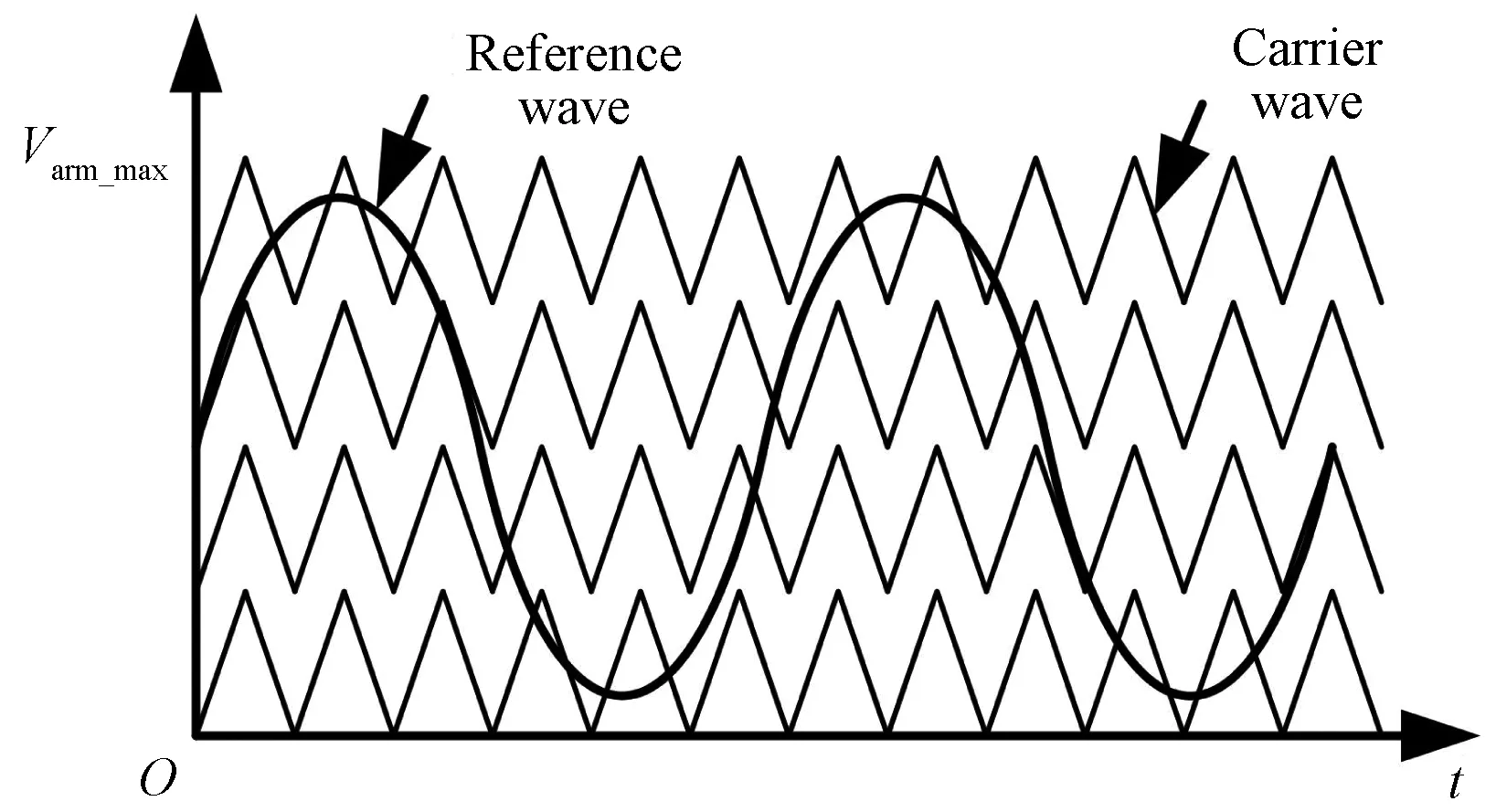
Fig. 3 PD-PWM method taking four SMs per arm for example
2 Proposed RSF SOC Balancing Strategy
In this paper, the individual balancing controller adopts the proposed RSF method shown in Fig. 4 to reduce the switching losses. As shown in Fig. 4, the SOC of active SMs would minus or plus a number according to the direction of the arm current. Then, the changed SOCs would be sorted in descending order. At last, the specific SMs would be determined to be active or inactive according to the required number of active SMsNonand the direction of the arm current. In detail, as the number of necessary active SMs does not change, the operation states of all SMs also do not change. When the number of necessary active SMs increases, the added SMs are selected from the inactive SMs. When the number of necessary active SMs decrease, the inactive SMs are selected from the active SMs. It should be noted that, in this method, whether the arm current is positive or negative, the SOCs of all SMs are sorted in descending order. As the arm current is positive, the active SMs are selected from the lastNonSMs. As the arm current is negative, the active SMs are selected from the topNonSMs.
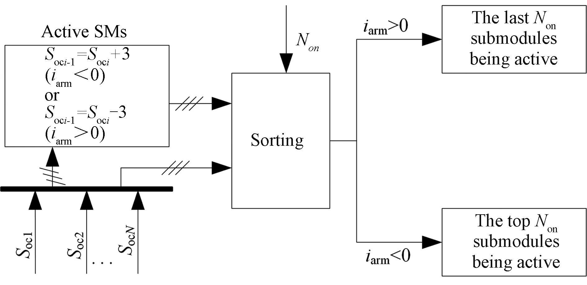
Fig. 4 Proposed RSF SOC balancing strategy
Taking one arm with four SMs(N=4) as an example, it assumes that the SOCs of the SMs are 0.900, 0.897, 0.898 and 0.899, and the active SMs are SM 3, SM 4 at present. Then, the expression for the SOCs and the number of active SMs could be given as
Soc1=0.900,Soc2=0.897,
Soc3=0.898,Soc4=0.899,
Non=2,N=4.
2.1 Positive arm current
When the arm current is positive, the SOC of the active SM would be sorted after minus a number. It should be noted that this number must be bigger than 1. In this example, 3 is adopted. Then, the new SOCs of the four SMs are
Soc1_1= 0.900,Soc2_1= 0.897,
Soc3_1= 0.898-3 = -2.102,Soc4_1= 0.899-3 = -2.101.
TheSoc1_1,Soc2_1,Soc3_1, andSoc4_1are the new values ofSoc1,Soc2,Soc3, andSoc4, respectively.
Then, the new descending sorting result isSoc1_1,Soc2_1,Soc4_1andSoc3_1.
(1) Assuming the number of the active SM is 2 at the next moment, the expected active SMs are SM 3 and SM 4, which are with lower SOC.
According to the proposed RSF strategy, the top 2(N-Non= 4-2 = 2) SMs are removed, the last two SMs are in active. As shown in Fig. 5(a) , the SM 1 and SM 2 are removed; the SM 3 and SM 4 are in active. The output of the RSF strategy is the expected result. The dashed frame represents the active SMs at this moment, and the elliptical frame represents the output results of the RSF method to be the active SMs at the next moment.
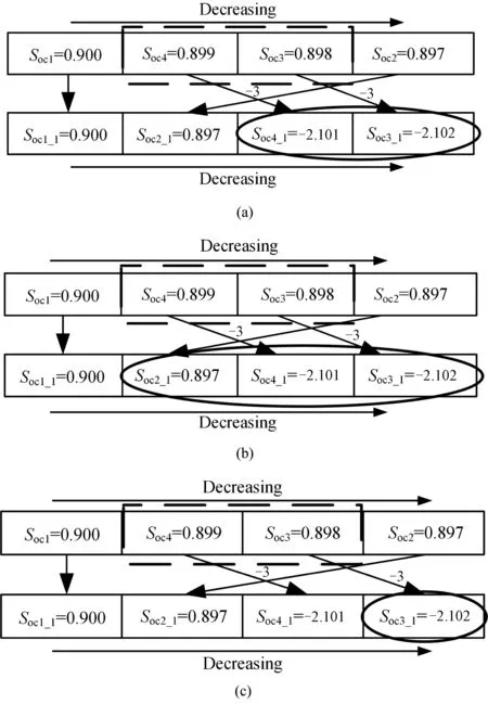
Fig. 5 Outputs of the proposed RSF method with the positive arm current at the next moment: (a) two active SMs;(b) three active SMs; (c) one active SM
(2) Assuming the number of the active SM is 3 at the next moment, the expected active SMs are SM 2, SM 3, and SM 4, which are with lower SOC.
According to the proposed strategy, the top 1(N-Non= 4-3 = 1) SM is removed, the last three SMs are in active. As shown in Fig. 5(b), the SM 1 is removed, the SM 2, SM 3, and SM 4 are in active. The output of the RSF strategy is the expected result.
(3) Assuming the number of the active SM is 1 at the next moment, the expected active SM is SM 3, which is with lower SOC.
According to the proposed RSF strategy, the top 3(N-Non= 4-1 = 3) SMs are removed, the last one SM is in active. As shown in Fig. 5(c), the SM 1, SM 2, and SM 4 are removed, the SM 3 is in active. The output of the RSF strategy is the expected result.
2.2 Negative arm current
When the arm current is negative, the SOC of the active SM would be sorted after plus a number. It should be noted that this number must be bigger than 1. In this example, 3 is adopted. Then, the new SOCs of the four SMs are
Soc1_1= 0.900,Soc2_1= 0.897,Soc3_1= 0.898+3 = 3.898,Soc4_1= 0.899+3 = 3.899.
The new descending sorting result isSoc4_1,Soc3_1,Soc1_1andSoc2_1.
(1) Assuming the number of the active SM is 2 at the next moment, the expected active SMs are SM 3 and SM 4, which are with higher SOC.
According to the proposed strategy, the top 2(Non=2) SMs are in active, the last two SMs are removed. As shown in Fig. 6(a), the SM 1 and SM 2 are removed; the SM 3 and SM 4 are in active. The output of the RSF strategy is the expected result.
(2) Assuming the number of the active SM is 3 at the next moment, the expected active SMs are SM 1, SM 3, and SM 4, which are with higher SOC.
According to the proposed RSF strategy, the top 3(Non= 3) SMs are in active, the last one SM is removed. As shown in Fig. 6(b), the SM 2 is removed, the SM 1, SM 3, and SM 4 are in active. The output of the RSF strategy is the expected result.
(3) Assuming the number of the active SM is 1 at the next moment, the expected active SM is SM 4, which is with higher SOC.
According to the proposed RSF strategy, the top 1(Non= 1) SM is in active, the last three SMs are removed. As shown in Fig. 6(c), the SM 1, SM 2, and SM 3 are removed, the SM 4 is in active. The output of the RSF strategy is the expected result.

Fig. 6 Outputs of the proposed RSF method with the negative arm current at the next moment: (a) two active SMs;(b) three active SMs; (c) one active SM
3 Simulation Results and Discussion
A three-phase MMC system with four SMs per arm is constructed in MATLAB/Simulink surroundings. The traditional sorting method and the proposed RSF sorting method are both applied in the constructed system. The simulation parameters are shown in Table 1. The simulation time is set as 50 s, and the initial SOCs of all batteries are randomly distributed between 0.899-0.900.
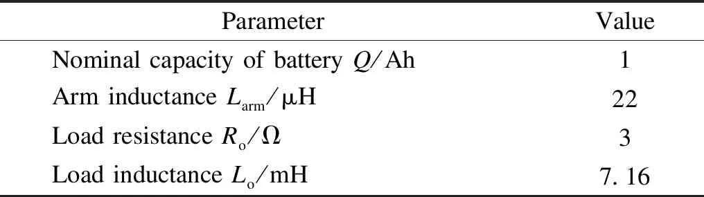
Table 1 Parameters of simulation
3.1 Application of traditional individual balancing controller
When applying the traditional individual balancing controller, the simulation results are shown in Fig. 7. The top waveform of Fig. 7(a) is the drive signal for the SM 1 under the unbalancing condition, the bottom waveform of Fig. 7(a) is the drive signal for the SM 1 under the balancing condition. The obvious change of the SF is caused by the traditional sorting procedure, due to the unnecessary switching transitions under the balancing condition.
The waveform of Fig. 7(b) is the average phase SOC and the SOCs of the all the SMs, where the SOC_avg_a, SOC_avg_b, and SOC_avg_c are the average SOCs of phases a, b, and c, respectively. It is obvious that all the SMs are well balanced after 15 s. The top waveform of Fig. 7(c) is the load current under the unbalancing condition, the bottom waveform of Fig. 7(c) is the load current under the balancing condition. The top waveform of Fig. 7(d) is the converter output voltage under the unbalancing condition, the bottom waveform of Fig. 7(d) is the converter output voltage under the balancing condition. As shown in Figs. 7(c) and 7(d), both the output current and voltage of the converter are with very low THD, and they have no obvious change during the balancing process.

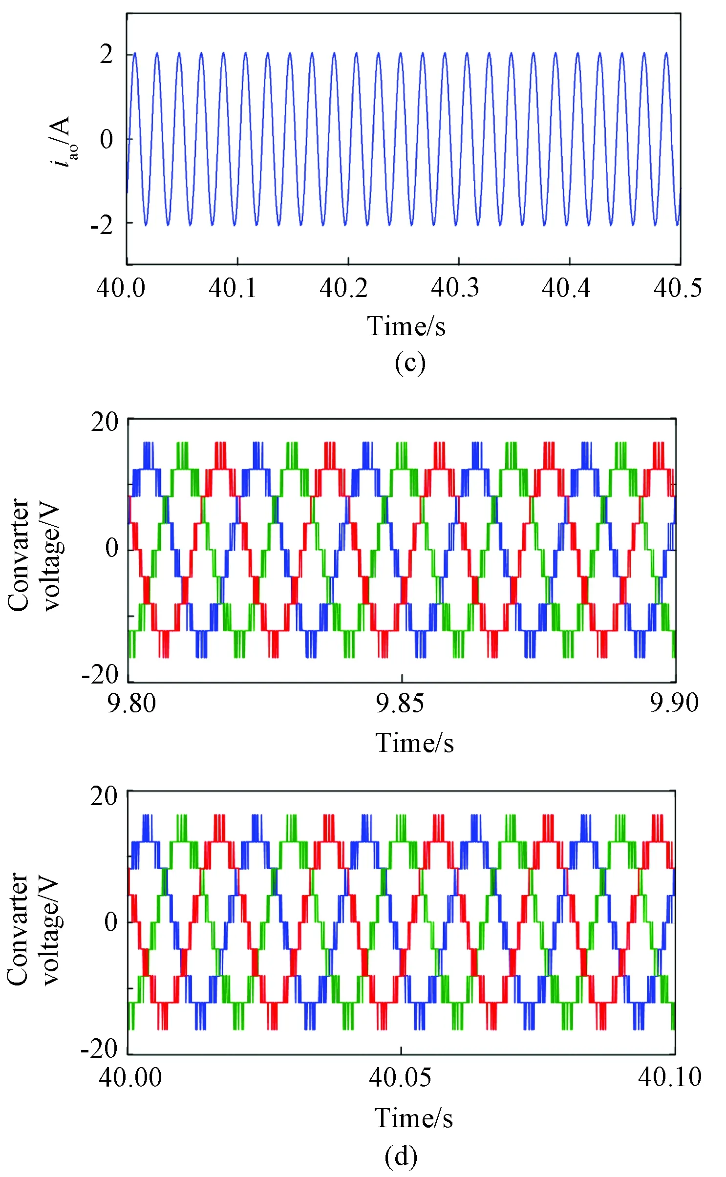
Fig. 7 Simulation results of the MMC using the traditional sorting procedure under the unbalancing condition and the balancing condition: (a) drive signal; (b) average of the phase SOC and the SOCs of all the SMs; (c) load current; (d) converter voltage
3.2 Application of proposed individual balancing controller
When applying the proposed individual balancing controller, the simulation results are shown in Fig. 8. The top waveform of Fig. 8(a) is the drive signal for the SM 1 under the unbalancing condition, the bottom waveform of Fig. 8(a) is the drive signal for the SM 1 under the balancing condition. By comparing Fig. 8(a) with Fig. 7(a), the SF under the proposed sorting method is much lower than the traditional one, especially under the balancing condition.
The top waveform of Fig. 8(b) is the average phase SOC, and the bottom waveforms of Fig. 8(b) are the SOCs of the all the SMs, it is obvious that all the SMs are also well balanced after 15 s. The top waveform of Fig. 8(c) is the load current under the unbalancing condition, and the bottom waveform of Fig. 8(c) is the load current under the balancing condition. The top waveform of Fig. 8(d) is the converter output voltage under the unbalancing condition, the bottom waveform of Fig. 8(d) is the converter output voltage in the balancing condition. As shown in Figs. 8(c) and 8(d), both the output current and voltage of the converter are with very low THD, and they have no obvious change during the balancing process.

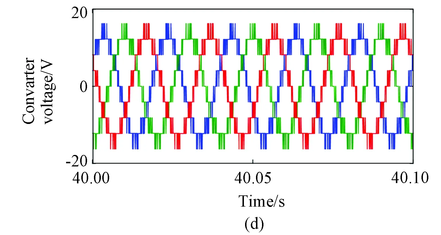
Fig. 8 Simulation results of the MMC using the proposed sorting procedure under the unbalancing condition and the balancing condition:(a) drive signal;(b) average of the phase SOC and the SOCs of all the SMs;(c) load current;(d) converter voltage
Through comparing all the waveforms adopting the two methods respectively, the main difference is the drive signal waveform. It should be clear that the discharge and charge of the battery is a relevantly slow process. Under the unbalancing condition, the SOCs of all SMs have a big difference among each other. During a certain period of time, the traditional sorting results do not have a big change, which results in fewer unnecessary switching transitions. Therefore, the proposed sorting method does not reduce the SF obviously. And at the same time, it also ensures that the negative impact of the proposed sorting algorithm on the system is very small. Under the well-balancing condition, the SOCs of all SMs have a very small difference among each other. During a certain period of time, the traditional sorting results would have a big change, which results in a lot of unnecessary switching transitions and high SF as well as switching losses. As a result, the proposed sorting procedure eliminates the unnecessary switching transitions to reduce the switching losses.
4 Conclusions
In this paper, an SOC balancing algorithm with RSF is proposed. The principle of the proposed method is illustrated in detail. By adding priority level in the sorting process, the proposed RSF algorithm features good balancing performance in not only the unbalanced state, but also the balanced state. The results are verified through extensive simulations in MATLAB/Simulink surroundings.
 Journal of Donghua University(English Edition)2021年6期
- Journal of Donghua University(English Edition)的其它文章
- Strain Pseudomonas putida PAO-1 Isolate with Polyphosphate Accumulating and Elongation Ability
- Theoretical Model on Transformation Factors of Scientific and Technological Achievements under the Belt and Road Initiative
- Exploitation of Waste Heat from a Solid Oxide Fuel Cell via an Alkali Metal Thermoelectric Converter and Electrochemical Cycles
- Gait Recognition System in Thermal Infrared Night Imaging by Using Deep Convolutional Neural Networks
- Feature Fusion Multi_XMNet Convolution Neural Network for Clothing Image Classification
- Data Augmentation Based Event Detection