Development of a combined interferometer using millimeter wave solid state source and a far infrared laser on ENN’s XuanLong-50(EXL-50)
2022-07-13 00:36:34JiaxingXIE解家興XuechaoWEI魏學朝HaiqingLIU劉海慶SongjianLI李松健JiboZHANG張際波YuanYAO姚遠YunfeiWANG王云飛andYinxianJIE揭銀先
Plasma Science and Technology 2022年6期
Jiaxing XIE (解家興),Xuechao WEI (魏學朝),Haiqing LIU (劉海慶),Songjian LI (李松健),Jibo ZHANG (張際波),Yuan YAO (姚遠),Yunfei WANG (王云飛),4 and Yinxian JIE (揭銀先)
1 Institute of Plasma Physics,Hefei Institutes of Physical Science,Chinese Academy of Sciences,Hefei 230031,People’s Republic of China
2 University of Science and Technology of China,Hefei 230026,People’s Republic of China
3 ENN Science and Technology Development Co.,Ltd,Langfang 065001,People’s Republic of China
4 Interdisciplinary Graduate School of Engineering Sciences,Kyushu University,Kasuga 816-8580,Japan
Abstract A millimeter wave solid state source-far infrared laser combined interferometer system (MFCI)consisting of a three-channel 890 GHz hydrogen cyanide (HCN) laser interferometer and a threechannel 340 GHz solid state source interferometer(SSI)is developed for real-time line-integrated electron density feedback and electron density profile of the EXL-50 spherical tokamak device.The interferometer system is a Mach-Zehnder type,with all probe-channels measured vertically,covering the plasma magnetic axis to the outermost closed magnetic plane.The HCN laser interferometer uses an HCN laser with a frequency of 890 GHz as a light source and modulates a 100 kHz beat signal by a rotating grating,giving a temporal resolution of 10 μs.The SSI uses two independent 340 GHz solid-state diode sources as the light source,the frequency of the two sources is adjustable,and the temporal resolution of SSI can reach 1 μs by setting the frequency difference of the two lasers at 1 MHz.The main optical path of the two interferometers is compactly installed on a set of double-layer optical platform directly below EXL-50.Dual optical path design using corner cube reflectors avoids the large support structures.Collinear the probebeams of two wavelengths,then the phase error caused by vibration can be compensated.At present,the phase noise of the HCN Interferometer is 0.08 rad,corresponding to a line-integrated electron density of 0.88×10¹⁷ m?2,one channel of measuring result was obtained by the MFCI system,and the highest density measured is about 0.7×10¹⁹ m?2.
Keywords: plasma diagnostics-interferometry,spectroscopy and imaging,nuclear instruments and methods for hot plasma diagnostics
1.Introduction
Electron density is an indispensable parameter in experimental studies of fusion plasmas,and interferometry is a widely used method for measuring plasma electron density on tokamak fusion experimental devices,which can measure the time evolution of line integral electron density with high time resolution and give reliable density profile with multi-channel measurements.EXL-50 is a medium-sized spherical tokamak with a completely noninductive current drive and has been in routinely operation since the middle of 2019 [1].A single-channel tangential 140 GHz microwave interferometer has been developed on EXL-50.However,in order to meet future experimental requirement in higher and wider electron density operational regime,it is necessary to develop a multi-channel density measurement system,combined with different wavelength sources for covering the wider electron density range and giving plasma electron density profile.The multi-channel suitable wavelength interferometer density measurement can provide support for EXL-50 to evaluate the energy confinement time,can help to achieve electronic Bernstein wave heating and break the cutoff density limit,and can also provide density feedback signals for physics experiments to achieve real-time density control.To achieve this,the HCN laser interferometer at 890 GHz (cutoff density 9.8× 10²¹m?3) and the solid-state source interferometer at 340 GHz (cutoff density 1.27×10²¹m?3) were selected for multi-channel measurements to obtain the electron density profile from the plasma magnetic axis to the outermost closed magnetic plane,satisfying the electron density diagnostic range of 1×10¹⁶-1×10²⁰m?3on EXL-50.
Interferometers for simultaneous measurements at dual wavelengths have the natural advantage of developing compensation interferometer for vibrations [2].HCN interferometer is a completely localized and mature technology,it has been successfully developed in various tokamak fusion experimental devices.For instance,a single-channel far-infrared HCN interferometer for measuring line averaged electron density on EAST has been developed in 2008 [3].A seven-channel HCN interferometer for measuring electron density profiles has been successfully constructed on J-TEXT in 2015[4].Solid-state source interferometer has the advantages of small space occupation,stable operation,and simple operation and maintenance,etc.It has been applied on some tokamaks like Keda Torus eXperiment (KTX) [5] and DIII-D [6].In 2019,a single-channel 0.65 THz solid-state source interferometer was successfully developed on EAST,obtaining measurement results which are in agreement with those of the HCN laser interferometer and polarization interferometer (POINT) on EAST [7].This paper describes the design and preliminary results of the MFCI on EXL-50,mainly including optical design,mechanical design,system layout and preliminary results,and gives a brief discussion and future plans at the end of the paper.
2.System design
The conceptual design of the MFCI is shown in figure 1,where the red line is the HCN laser beam and the blue line is the solidstate source beam.Both the HCN laser interferometer and the SSI are Mach-Zehnder type interferometers,which must generate the beat frequency required for heterodyne detection through phase modulation.The beat frequency determines the temporal resolution of MFCI system.The HCN laser interferometer uses a rotating grating for phase modulation,while the SSI uses two solid-state sources with adjustable frequency differences to obtain the intermediate frequency (IF) signal.Both sets of interferometers have a shared channel so that two wavelengths of laser light are measured simultaneously,and the vibration error of this measurement channel can be eliminated in the measurement results.
The three-channel HCN laser interferometer mainly measures the plasma core region around the magnetic axis and occupies three windows in the center of the device-offset,while the three-channel SSI mainly measures the plasma edge region and occupies three windows against the outside.In the design,the SSI can be extended with a fourth channel,which is shared with the HCN laser interferometer,to develop a compensation interferometer.In order to save space around EXL-50 and avoid the use of large support structures,the detection optical path is designed as a dual optical path,and a corner cube reflector is installed in the top window of the device to make the laser return in the original path.The MFCI system mainly includes a HCN laser,two solid-state diode source,optical system (including rotating grating,optical lens,optical reflectors,corner cube reflectors,waveguides,beam splitters etc),detectors,phase meter and data acquisition system.
2.1.Sources and detector
The sources used in MFCI are a HCN laser and two solid-state diode sources.HCN laser is a gas laser with a resonant cavity length of 3 m,the operating substance is a mixture of nitrogen,methane and hydrogen gas with a ratio of N2:CH4:H2=1:1:5[8].HCN laser is electrically excited continuous wave laser,the output power is more than 10 mW at a wavelength of 337 μm for the EH11mode [9].The solid-state diode source output power is above 10 mW in 340 GHz band,original input frequency is in Lo1=10.6 GHz band,32 times frequency doubling,oscillator frequency within 12 MHz is continuously adjustable,frequency modulation step is better than 32±3 kHz,differential frequency drift between two solid-state sources is less than±100 kHz.The HCN laser interferometer and SSI use AlGaN/GaN-HEMT detectors with response frequencies of 100 kHz and 1 MHz,respectively.The NEP of the detector is 10 pW Hz?1/2and the sensitivity is 250 mV mW?1.
2.2.Mechanical and optical design
The overall layout of the combined interferometer is mainly divided into five parts: HCN laser system in the laser room,waveguide transmission system,optical path system of HCN interferometer under the device,SSI system under the device and the corner cube reflector fixed in the top window as shown in figure 2.To save space directly below the EXL-50 and to facilitate maintenance,the HCN laser system was placed against the wall on the negative level of the laboratory hall and a laser room was built for it.The laser room can provide an electromagnetic shielding,dust-free,vibration reduction and constant temperature operating environment for HCN laser system,the distance between the HCN room and the table below EXL-50 is about 6.5 m.A dual waveguide is used to transmit the beam from the laser room to below the EXL-50.Due to the limited space below the device,a doublelayer optical platform was designed to mount the optical path system of MFCI.The design needs to consider the possibility of expanding the number of probe channels for SSI in the future,and the SSI has a longer wavelength than the HCN interferometer,and the close proximity to the window is more conducive to the optical path calculation and reduces the laser power loss,so the SSI system is installed on the upper layer of the optical platform,and the HCN laser interferometer tabletop optical path is installed on the lower layer.
Figures 3(a) and (b) show the layout of the window above the device,the HCN laser interferometer occupies three windows in the central direction of the device,among which the outermost window is shared with the SSI.The SSI has four vertical measurements and occupies four windows on the outside of the device.In the MFCI system,the corner cube reflectors are the main component that determines the propagation path and size of gaussian beam [10].The three windows used in the HCN laser interferometer are arranged linearly with a window spacing of 125 mm,and the three outermost windows used in the SSI are distributed in the shape of a square triangle with a spacing of 125 mm between each two windows.The installation structure of the corner cube reflector is shown in figures 3(c)and(d),and the corner cube reflector is installed in the stainless steel base,which is directly mounted on the window flange through four stainless steel columns.The diameter of the window is 70 mm,the beam waist of HCN laser interferometer and solid source interferometer at the corner cube reflector is 23.8 mm and 46.5 mm respectively,ensuring the processing accuracy and avoiding the loss of laser power,the diameter of the corner cube reflector is set to 60 mm.The material of the corner reflector is aluminum gold plating,and the preparation accuracy is better than 50 arc-seconds,since the corner reflector is mounted on the outside of the window,there is no need to consider the effect of high temperature and plasma environment on the corner cube reflector.The window temperature of EXL-50 can reach 200 °C during operation,so the quartz crystal is chosen instead of TPX lens for the window material,and the transmission rate of quartz crystal for both wavelengths is over 90% after precise thickness calculation for 337 and 882 μm laser.
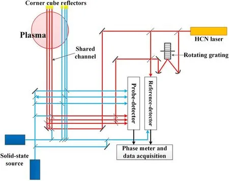
Figure 1.Schematic of MFCI system.

Figure 2.The overall layout of the composite interferometer on EXL-50.

Figure 3.(a) Location of diagnostic window above the device,(b) MFCI window layout,(c) fixed structure of corner cube reflector,(d) corner cube reflector.

Figure 4.(a) HCN laser table in laser room,(b) optical path system of HCN interferometer below EXL-50.
The optical layout of the MFCI system was designed with ZEMAX software [11] using Gaussian optics,and the beam profile diameter (D) and the beam waist diameter (d) of the main position in the optical path is given in figures 4 and 5.Figure 4(a) shows the optical path design of HCN laser table,where the HCN laser and other optical devices are fixed on an optical table,and the laser output from the HCN laser is divided into a probe beam and a reference beam,and the reference beam needs to be phase-modulated by a rotating grating,then part of the two beams are combined on the table into the reference-detector,and the other part enters two dielectric waveguides (Acrylic tubes of 80 mm inner diameter) with a length of 5 m,and is transmitted by the waveguides to the bottom of EXL-50.The material of rotating grating is brass.Compared with aluminum grating,the hardness of brass grating is higher,and the grating grooves are less likely to be damaged.Compared with titanium grating,brass grating has better reflectivity and less power loss to far-infrared laser.The rotating grating is 8 mm in thick and 122 mm in diameter,and is directly connected to the output shaft of the motor,the number of grooves is G=1825,and the blaze angle is 54°.The motor speed is set as 54.8 rev s?1,which will produce a beat frequency signal of 100 kHz [12].

Figure 5.SSI system.
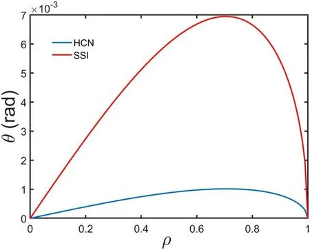
Figure 6.Radial distribution diagram of refraction angle.

Figure 7.(a) Shared channel beam splitter location,(b) schematic diagram of compensation interferometer.
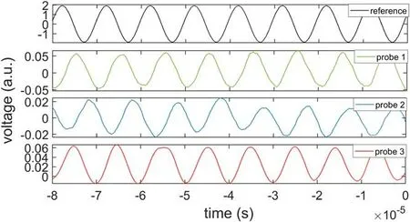
Figure 8.100 KHz beat frequency signal of HCN laser interferometer.
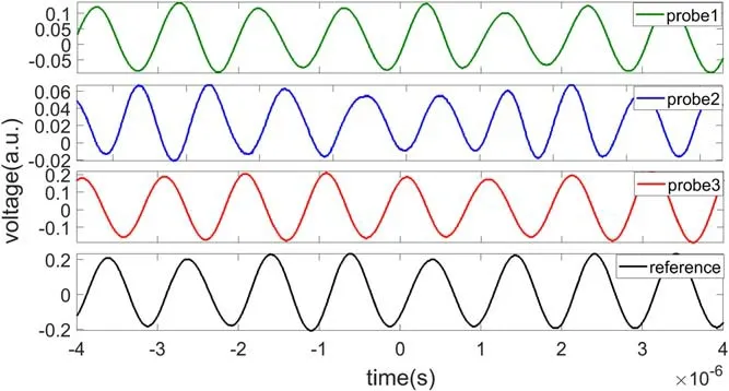
Figure 9.1 MHz beat frequency signal of SSI.
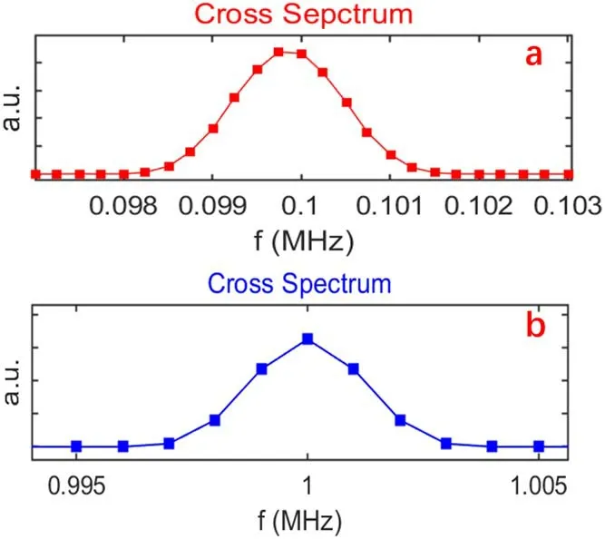
Figure 10.The cross spectra of two IF signals of HCN laser interferometer (a) and SSI (b).
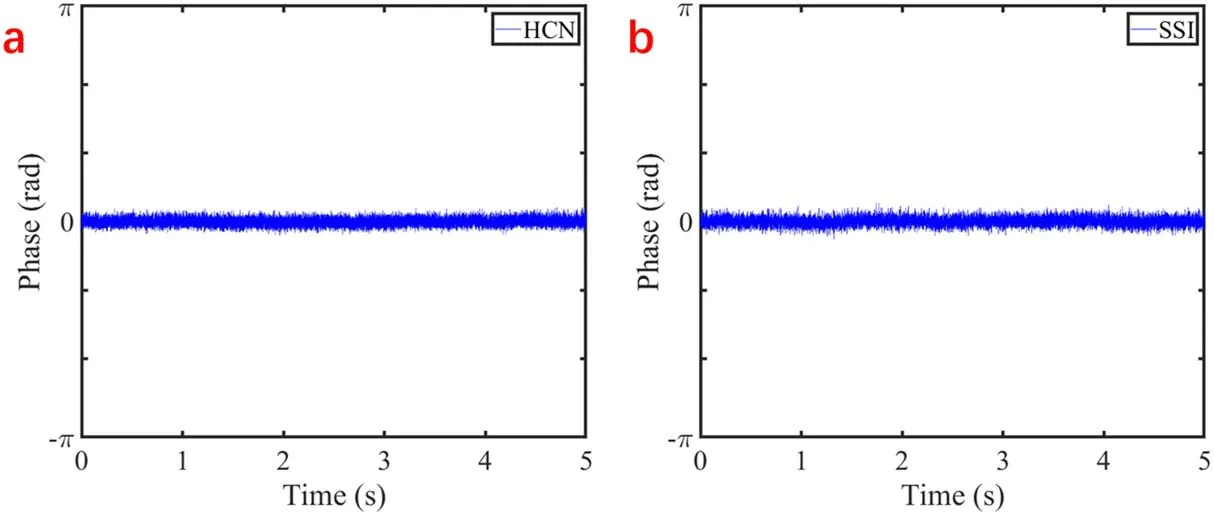
Figure 11.(a) The phase noise of HCN laser interferometer,(b) the phase noise of SSI.

Figure 12.Density data of HCN laser interferometer on EXL-50(shot#11546).
The optical design of the HCN laser interferometer below EXL-50 is shown in figure 4(b),and all the optics are mounted on a 2.5 m×1.8 m non-magnetic optical table.The probe beam is transmitted over long distances through a telescope system consisting of convex and concave mirrors,and is divided into three beams of perpendicularly incident detection laser into EXL-50 by the 45-degree angle beam splitter directly below the window,and then reflected by the corner cube reflector in the upper window and returned the same way,and the returned beam is reflected by the beam splitter above the 45-degree angle beam splitter into the optical path of the table.The reference beam is divided into three beams by beam splitters,which are combined with the probe beams returned from the corner reflector to form the beat frequency signal and enter the probe-detectors.The SSI system is shown in figure 5,the whole system table is located 60 cm above the HCN laser interferometer table,supported by multiple supporting legs standing on the HCN interferometer table,and the height of the supporting legs can be finely adjusted to facilitate the level adjustment of the SSI table.The SSI table is a 20 mm thick optical aluminum plate with grooves cut at some positions to avoid blocking the probe beam of the HCN laser interferometer.The optical path design of the SSI is similar to that of the HCN laser interferometer,the difference is that the probe beam and the reference beam of the SSI are generated by two solid-state sources respectively,and the frequency difference between the two solid-state sources is 1 MHz without a rotating grating for phase modulation.
When the propagation direction of the incident beam in the plasma has an angle with the plasma electron density gradient,the incident beam will be deflected due to refraction effect,and finally the outgoing beam will deviate from the incident beam to some extent.For the axisymmetric parabolic plasma profile [13],if the plasma density distribution is
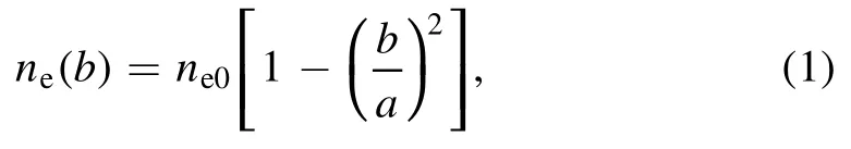
where b is the beam collision parameter,ne0is the density of the plasma center,the deviation angle of probe beam caused by refraction effect is
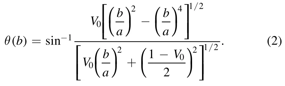
The distance between the diagnostic window and the plasma center is 1.5 m,the offset (Δ) of refraction effect in the upper window was estimated based on the position of HCN laser interferometer and SSI,ΔHCNis about 0.3 mm and ΔSSIis about 7 mm.Due to the use of a corner cone,the offset of the lower window caused by refraction effect is twice that of the upper window,so the offset of the lower window is ΔHCN=0.6 mm andΔSSI=14 mm.Thus,it can be seen that refraction effect has little influence on HCN interferometer.Under the condition of high-density discharge,the refraction effect will cause the SSI with wavelength of 882 mm to lose some power at the corner cube reflector and the lower window.However,judging from the window diameter and beam diameter,the maximum power loss of beam will not exceed 10%,and for the detector,the focusing mirror in front of the detector causes the offset of the beam from the refraction effect to be small at the detector position,so the effect of refraction on SSI in MFCI system is acceptable.
2.3.Compensation interferometer
This compensation interferometer mainly compensates the vibration of the corner cube reflector on the top of the device.Since the corner cube reflector is directly fixed on the EXL-50,when the EXL-50 is discharging (the phase of density climbing and falling),the corner cube reflector will produce several tens microns vibration along with the device.
The compensation interferometer can be developed on the shared channel of HCN laser interferometer and SSI shown in figure 5.The installation position of the beam splitter and the schematic diagram of the compensation interferometer are shown in figure 7.S1 and S2 are nickel mesh beam splitters on HCN laser interferometer,S3 and S4 are nickel mesh beam splitters on SSI.Considering the power distribution of the entire optical path system,S1 and S2 use a nickel mesh of 200 Lines per Inch (LPI),S3 and S4 use a nickel mesh of 50 LPI.Through tests,the transmittance of 200 LPI nickel mesh to 337 μm laser is about 60%,the transmittance of 50 LPI nickel mesh to 882 μm laser is about 60%,and the transmittance of 50 LPI nickel mesh to 337 μm laser is more than 80%.The HCN laser loses some power when it passes through the 50 LPI nickel mesh,however,this design has the possibility to make two interferometer systems measure simultaneously and thus perform vibration compensation.
3.Preliminary test results on EXL-50
The optical path system of the MFCI system has been installed.HCN laser interferometer has obtained three probe channels of 100 kHz beat frequency signal,and SSI has obtained three probe channels of 1 MHz beat frequency signal,as shown in figures 8 and 9.The cross spectra of the two IFs in the two interferometers are calculated respectively to estimate the IF bandwidth.HCN is about 3 kHz,SSI is about 5 kHz,as shown in figure 10.
The root-mean-square of phase noise of the HCN laser interferometer and SSI output from the phase meter is about 0.09 rad and 0.14 rad respectively,as shown in figure 11.High frequency noise of MFCI is mainly from electronic noise of detector,phase meter and acquisition system,low frequency noise is mainly from vibration of optical system.For the HCN laser interferometer,every 2π phase change corresponds to a line-integrated electron density of 6.62×10¹⁸m?2,so the phase noise corresponds to an electron density of 0.99×10¹⁷m?2.For the SSI,every 2π phase change corresponds to a lineintegrated electron density of 2.52×10¹⁸m?2,so the phase noise corresponds to an electron density of 0.56×10¹⁷m?2.
During the experiment of EXL-50,electron density data was obtained from the one nearest to the magnetic axis of the HCN laser interferometer,the highest line-integrated electron density obtained by HCN laser interferometer is about 0.7×10¹⁹m?2,as shown in figure 12.At present,the plasma cross section has not covered the windows of SSI,so the density data has not been measured by SSI.
4.Conclusions and future plan
A millimeter wave solid state sources- far infrared laser combined interferometer system consisting of a three-channel 890 GHz HCN laser interferometer and a three-channel 340 GHz solid-source interferometer on EXL-50 has been designed and installed.The MFCI has been completed on EXL-50.At present,the phase noise of the HCN Interferometer is 0.08 rad,corresponding to a line-integrated electron density of 0.88×10¹⁷m?2,one channel of lineintegrated electron density was obtained by the MFCI system,and the highest density measured is about 0.7×10¹⁹m?2.In the interferometer commissioning process,the interference problem of electron cyclotron resonance heating (ECRH) to the detector needs to be solved,and the compensation interferometer system needs to be further developed to eliminate the vibration effect.At present,the plasma of EXL-50 has not yet covered at the SSI window.When the parameters of the EXL-50 device are upgraded in the future and the MFCI system obtains at least six channels of electron density data,the electron density profile will be achieved.
Acknowledgments
The authors express their gratitude to ENN Science and Technology Development Co.,Ltd for the technical support and help.This work is supported by the National MCF Energy R&D Program (Nos.2019YFE03040003 and 2017YFE0301205).This work is also supported in part by Key Program of Research and Development of Hefei Science Center,CAS (No.2019HSC-KPRD001).This work was partly supported by the Collaborative Research Program of the Research Institute for Applied Mechanics,Kyushu University.
 Plasma Science and Technology2022年6期
- Plasma Science and Technology的其它文章
- Investigation on the multi-hole directional coupler for power measurement of the J-TEXT ECRH system
- Neutronic analysis of Indian helium-cooled solid breeder tritium breeding module for testing in ITER
- Investigation on the electrode surface roughness effects on a repetitive selfbreakdown gas switch
- Roll-to-roll fabrication of large-scale polyorgansiloxane thin film with high flexibility and ultra-efficient atomic oxygen resistance
- Effect of shock wave formation on propellant ignition in capillary discharge
- The application of a helicon plasma source in reactive sputter deposition of tungsten nitride thin films