Sound-transparent anisotropic media for backscattering-immune wave manipulation
2022-08-31 09:57:18WeiWeiKan闞威威QiuYuLi李秋雨andLeiPan潘蕾
Chinese Physics B 2022年8期
Wei-Wei Kan(闞威威), Qiu-Yu Li(李秋雨), and Lei Pan(潘蕾)
School of Science,Nanjing University of Science and Technology,Nanjing 210094,China
Keywords: sound-transparent anisotropic media,acoustic bending waveguide,transformation acoustics
1. Introduction
Acoustic metamaterials are usually periodically arranged subwavelength structures[1–11]with acoustic properties that do not exist in nature, such as negative bulk modulus[2,12]and anisotropic mass density.[13–18]A metamaterial with anisotropic mass density is often named a metafluid[19–22]and implemented by periodically arranging subwavelength anisotropic structures in the matrix medium. Due to their possible applications in acoustic invisibility,[22]waveguiding,[23,24]and beam-splitting,[25]metafluids have attracted increasing attention. Acoustic invisibility, the technique to prevent incident waves from being affected by scattering objects,is one of the most discussed topics in this field.Coordinate transformation[26–28]is the most popular method to design such an invisibility cloak. Nevertheless, the required extreme material parameters are usually difficult to implement in broadband. Acoustic invisibility in free space is often limited to a narrow bandwidth or only effective along a specific direction, especially for large targets. On the other hand, important experimental demonstrations of invisibility cloaks have already been given for cloaking under different circumstances[29–35]such as ground cloaks, often composed of metafluids with anisotropic mass density.[17,18]
Other manners of wave manipulation,e.g.,wave-guiding and beam-steering,can be achieved similarly with coordinate transformation and metafluids. Previously, acoustic signals were usually transmitted with a straight waveguide in many applications,otherwise the wave would be reflected with a distorted wavefront due to diffraction or scattering. To guide an acoustic signal along a non-straight path[36]with low loss,one feasible manner is to construct a line defect in a phononic crystal. However, the waveguide mode corresponds to the defect modes of the phononic crystal,indicating the operating bandwidth is limited. A numerical demonstration of a metamaterial waveguide composed of alternating layered structures[37]was reported using a negative-index medium, but this is difficult to implement for broadband operation in practice. The metafluid-based waveguide[24]allowing for broadband operation is based on a radically different framework. The theoretical underpinning is applicable to other metafluid applications such as beam-shifting or beam-steering devices.[26]
As acoustic metafluids show potential significance in various wave manipulation approaches, the impedance modulating method of such an anisotropic medium is worthy of further study. Because the velocity distribution plays a more important role in wave manipulation,[32,38]reduced parameters by scaling the desired values are often used to simplify the implementation,which has proven successful in many experimental results[31,32]and sometimes is even valid at quite high frequency ranges where the medium dispersion is already obvious,[38]but generally, the impedance mismatch inevitably affects the desired wave manipulation effect due to impedance mismatch.[34]In this case,the introduced subwavelength structures scatter the sound waves while leading the wave along a specific path. Sound-transparent anisotropic structure[38]was proposed to deal with this problem, but to date,the experimental implementation of such an artificial material with exactly the required acoustic parameters in a broad operating bandwidth still remains a challenge.
In this paper, we analyze the scattering behavior of such anisotropic materials, and experimentally demonstrate the acoustic wave routing in 9 kHz–11 kHz through the anisotropic layers with negligible backscattering loss. The effective mass density and bulk modulus of the acoustic subwavelength anisotropic structures are independently modulated by tuning the unit configurations in proper order. The effective parameter range of the structures is broadened, so that the acoustic impedance of the anisotropic structure can be matched to the background medium to create an abnormal anisotropic sound-transparent effect. The anisotropic soundtransparent medium is implemented by properly arranging the subwavelength structures,and the sound-transparent effect is numerically and experimentally demonstrated in a bending waveguide, where the incident Gaussian pulse is allowed to transmit with its envelope and the wavefront nearly unchanged.
2. Scattering behavior analysis
For realizing the desired wave manipulation, the structures are usually designed with the technique of coordinate transformation and effective medium theory(EMT).As shown in Fig. 1(a), a cylinder composed of the metafluid is radiated by a plane acoustic wave with wavelength equal to the cylinder radius. If the actual parameters of the manufactured material strictly comply with the design requirements, acoustic waves could enter such an anisotropic medium with no reflection. It is assumed that the anisotropic medium is well coupled to the background and the anisotropy of its mass density is 2; then,according to transformation acoustics, the bulk modulus and the anisotropic mass density should beκ=κ0,ρx=1.4ρ0,andρy=0.7ρ0,to ensure the wave is not reflected at the interface.The numerical simulations in Fig.1 are performed by illuminating this anisotropic object with an incident acoustic plane wave from different directions,and the scattering pattern in the far-field is obtained using the exterior field calculation.The results(blue line)shown in Fig.1(b)reveal that the backscattering is nearly eliminated for the ideal medium with impedance matched to the background. This means the wave enters the medium with no scattering, but when it goes out from the anisotropic medium,strong forward scattering is observed due to phase mismatch between the sound fields inside and outside the metafluid. The corresponding results for other incident directions are calculated and shown in Figs. 1(c)–1(f), from which the same conclusion can be drawn. The backscattering(blue line)along the opposite direction of wave incidence is hardly observed for all the cases,indicating the unexpected feature of the metafluid that the impedance of the anisotropic medium has nothing to do with the direction. When the parameters are scaled by a factor of 2, the backscattering, although not strong, can be obviously observed (green lines),which means an extra scattered wave caused by impedance mismatch is added to the strong forward-scattered wave due to phase mismatch. There are two ways to deal with this forward scattering: guide the wave along a bent path without any scattering, i.e., by decreasing the beam width to a dimension much smaller than the metafluid, or transmit the signal in a waveguide, to avoid the phase mismatch at the interfaces of the metafluid and background when the wave exits.
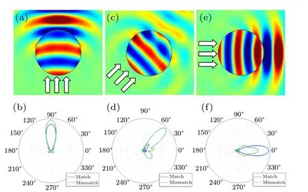
Fig.1. Scattered wave field for incident angles of 90?(a),45?(c),and 0?(e);and the far-field scattering pattern for incident angles of 90?(b),45?(d),and 0?(f). The incident direction is indicated with arrows.
3. Sound-transparent anisotropic structures
In order to demonstrate this effect, the following study is carried out in a waveguide. By proper design, an ideal bent waveguide made of sound-transparent anisotropic structures could guide incident sound waves through it without any scattering or reflection,and keep the wavefront unchanged as shown in Fig. 2. The acoustic field is calculated by solving a general partial differential equation with the density anisotropy taken into account. A 10 kHz plane wave is radiated at the leftmost end of the waveguide. The bent part is assumed to be symmetric and each half is composed of five segments with different bending angles. The bending angles can be arbitrary values only if the metafluid filled in the waveguide is properly designed according to the corresponding geometry configurations.When the waveguide is only filled with air,due to the scattering effect at the bent part,the sound wave will be reflected and the wavefront will be distorted.
To eliminate the reflection and restore the plane wave field, the required effective parameter distribution is derived using coordinate transformation.[22,27]Suppose there is a straight waveguide as the mimicked target, with a 10 kHz plane wave traveling through, generating the desired plane wave fieldp1(r). However, in the real bent waveguide in the laboratory, the metafluid is required to manipulate the field into the mimicked one. Taking the second segment,for example, with a new coordinater′=q1u1+q2u2, due to the invariant feature of the Hamiltonian under coordinate transformation,[28]the desired sound field and wave equations in the bent waveguide can be mathematically rewritten. By properly choosing the new coordinates according to the geometric relations, the mathematical form of the two different acoustic systems can be the same, and the field in the virtual straight waveguidep1(r) can be mimicked by the metafluid in the bent waveguide. Then, by implementing the coordinate transformationr′→r,the required parameters in the bent waveguide under Cartesian coordinates are
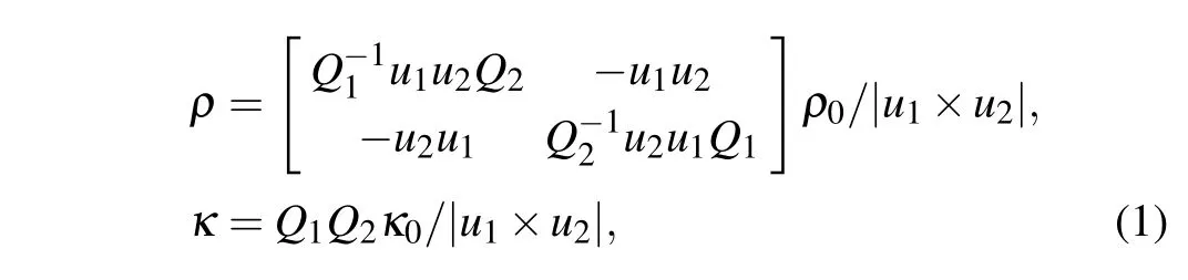
whereρ0andκ0are the mass density and bulk modulus of the air, which are assumed to be 1.29 kg/m3and 0.15 MPa,respectively.Q1andQ2are the metric factors defined asQi= (?x/?qi)+(?y/?qi). In this case, the two different systems will appear the same under detection. According to the geometric relationship betweenp1(r)andp1(r′),the vectors corresponding to the new coordinates areu1=cos(α)i+sin(α)j,u2=j,whereαis the bending angle.
The parameter distribution for other segments can be similarly obtained as described above. The acoustic field obtained by numerical calculation is given in Fig. 2, indicating that plane waves can pass through the bent waveguide without reflection,and the wavefront remains unchanged parallel to they-axis. It can also be observed that in this special medium,the direction of the wave vector and the phase velocity, given by the pressure gradient,is the same as the group velocity direction in the background medium.[27],and can be written asc0i,while the group velocity in the metafluid isc0(i+tan(α)j).
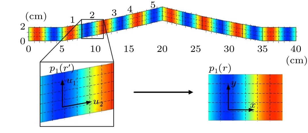
Fig. 2. Pressure field for the 10 kHz acoustic plane wave traveling through the desired low-reflection bent waveguide and the illustration of coordinate transformation.
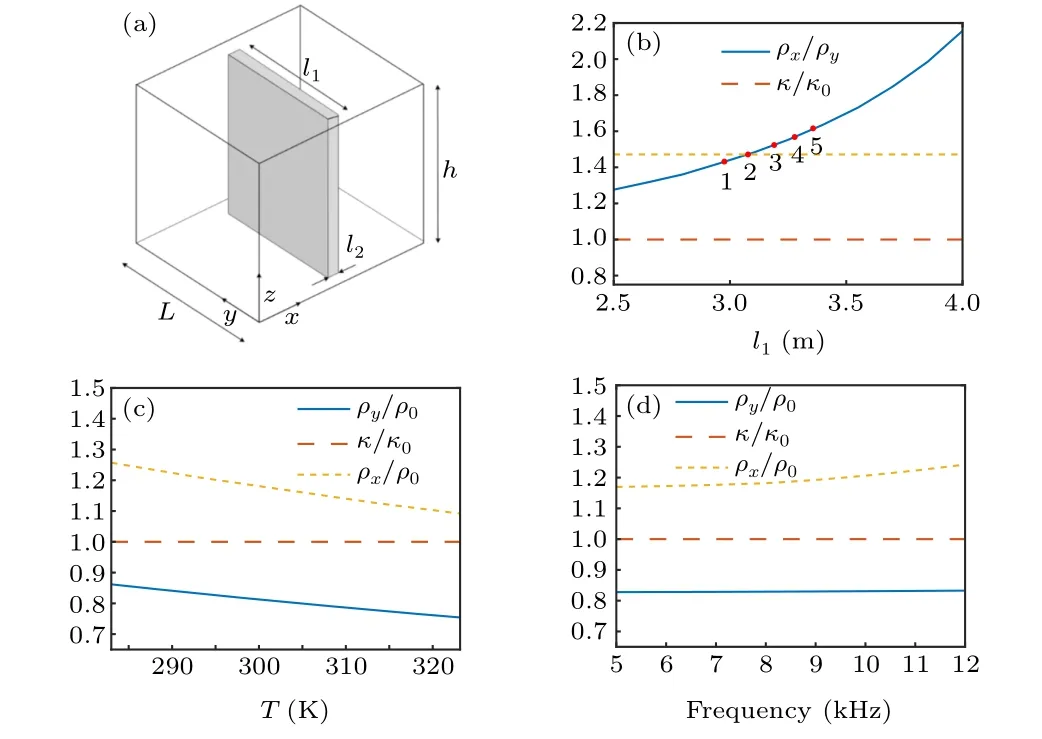
Fig. 3. (a) Unit with the rotated local axis; effective acoustic parameters of the anisotropic units when changing (b) l1, (c) temperature, and (d) frequency.
In order to generate the temperature distribution in the waveguide as shown in Fig. 4(a), there are two possible methods.[38,40]One is to use thin tungsten wire to form a sound-transparent mesh to increase the temperature in a specific area,but it is difficult to form a stable temperature distribution.Here we adopt the water bath method.The central segments of the quasi-two-dimensional bent waveguide(the third dimension is much smaller than the wavelength)is immersed in hot water in a rectangular container,as shown in Fig.4(b).The required temperature(blue line)does not change smoothly at the interface of different segments, which is difficult to achieve in practice. However,fortunately,the acoustic parameters of the medium are not very sensitive to the temperature within a certain range, so the desired piecewise temperature distribution can be approximated with a gradually varied temperature distribution, as shown in Fig. 4(a). The numerical simulation is performed by radiating the 10 kHz plane wave from one end of the waveguide, and the results are given respectively in Figs.4(c)and 4(d). The pressure field is demonstrated when the 10 kHz plane wave passes through the designed system and an air-filled bent waveguide. In the absence of the sound-transparent medium,the wave field near the bent part is distorted and reflected as expected. After the designed structure is arranged in the bent part of the waveguide and immersed in hot water, the desired plane wave field is restored,and the undisturbed wavefront in Fig. 4(c) demonstrates that the impedance of the designed structure is well matched to air.The results are in good agreement with Fig.2. The wavefront guided by the designed structure is still parallel to they-axis.The wave vector and phase velocity are in the same direction as in the background medium, while the group velocity and the direction of the acoustic energy flow are parallel to the rigid wall of the waveguide.
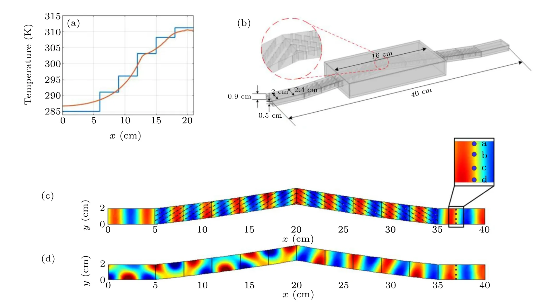
Fig.4. (a)Desired temperature distribution(blue)and simulated temperature distribution(red)in the waveguide with the water bath. (b)Schematic of the waveguide with the hot water container. Pressure field in the bent waveguide filled with metafluid(c)and air(d).
In addition, the time-domain simulation results in Fig. 5 also demonstrate the sound-transparent feature of the designed metafluid and the abnormal transmission effect. The incident acoustic signal is assumed to be a 0.8 ms Gaussian pulse modulated by a 10 kHz sinusoidal signal. The transmitted signals of the bent waveguide filled with sound-transparent medium and filled with air are recorded at the four positions a–d marked in Fig. 4(c). As shown in Fig. 5, with the designed sound-transparent media (red), the scattered signal is suppressed, and the transmitted signal is maintained similar to the incident signal. As the detection position changes, the transmitted signal may be different, e.g., the scattered signal(blue) at point c is comparatively small due to the small amplitude of the scattering mode at this point. However, for all the cases, the delayed scattered signal always remains significantly smaller (red) than the results for the bent waveguide without the metafluid (blue) at the same location, indicating that the metafluid can lead the sound wave through the bent waveguide without obvious wave scattering or distortion. The averaged transmission spectrum calculated from the time domain results by Fourier transform is shown in Fig.5(b). Several minima of transmission (blue) can be observed at frequencies around 9 kHz and 11 kHz when no structures are filled in the waveguide,while the fluctuation of transmission is much smaller after the designed structures are arranged there(red). The valley in the transmission at around 9 kHz suggests that the acoustic wave in this frequency is reflected by the bending waveguide. This reflection is avoided after arranging the metafluid in the waveguide,suggesting the medium works well in the corresponding frequency range.
The performance of the structures described above is also experimentally verified. The anisotropic structures, the waveguide, and the water container are fabricated with 3D printing as shown in Fig. 6. The photo in Fig. 6(b) is taken from one side of the waveguide to show the inside anisotropic structures. The signals are measured at the same positions as described above in Fig. 4. The 1/8 inch microphone is mounted in 3D printed shells fabricated with different mounting holes and filled with sound-absorbing foam. Changing the measuring position is done by changing different mounting shells. Still two cases are considered: the bent waveguide filled with air,and filled with the designed metafluid as shown in Figs.6(b)–6(c).Water at 318 K is pumped from the thermostat water bath to form water circulation through the container around the waveguide, so the water filled in the rectangular container surrounding the central part of the waveguide is expected to generate the desired temperature distribution in the waveguide. After the temperature in the waveguide becomes steady, the sinusoidal modulated 0.8 ms Gaussian pulse with 10 kHz central frequency is excited with an aluminum ribbon tweeter speaker at one end of the waveguide. The transmitted signal is received by the inserted microphone. the signals are then preamplified and recorded by the digital oscilloscope. A scheme and photo of the experimental setup are given in Figs. 6(a)–6(c), and the measured signals are shown in Fig.6(d).
From the results shown in Fig.6(d),it can be seen that the waveguide filled with the designed metafluid(red)has a significantly reduced scattering signal compared with the waveguide without any structure inserted (blue), proving that the structure can guide the acoustic wave as expected, along the bent waveguide without distorting the signals. With the designed metafluid, the transmitted signals remain almost the same as the incident Gaussian pulse, while the signal pulse is obviously distorted and broadened by the bent part of the waveguide without metafluid. As shown in Fig. 6(e), the averaged spectral response is calculated from the measured signals in Fig.6(d).Through spectrum analysis,it is also verified that the sound energy at around 9 kHz is blocked by the bent waveguide with only air(blue)while the fluctuation of transmission becomes smaller after the designed metafluid is arranged(red).The difference between experiment and simulation is caused by some practical facts; e.g., the speaker is not an ideal line source,which is easy to implement in simulation but difficult to generate in practice. For all the cases, the eliminated scattering and the abnormal transmission effect demonstrate the good performance of the designed anisotropic structure in the bent waveguide.
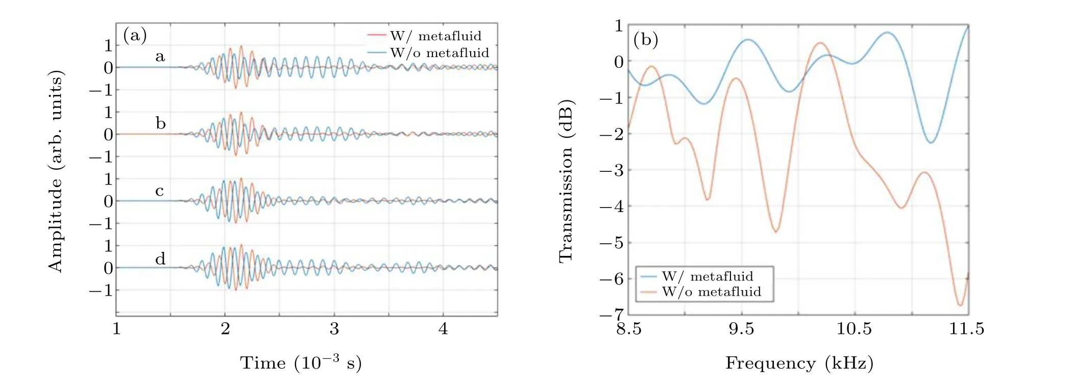
Fig.5. (a)Time domain simulation results: the transmitted signals at different positions of the bent waveguide filled with air(blue),and filled with the sound transparent metafluid(red). (b)Averaged transmission spectrum.
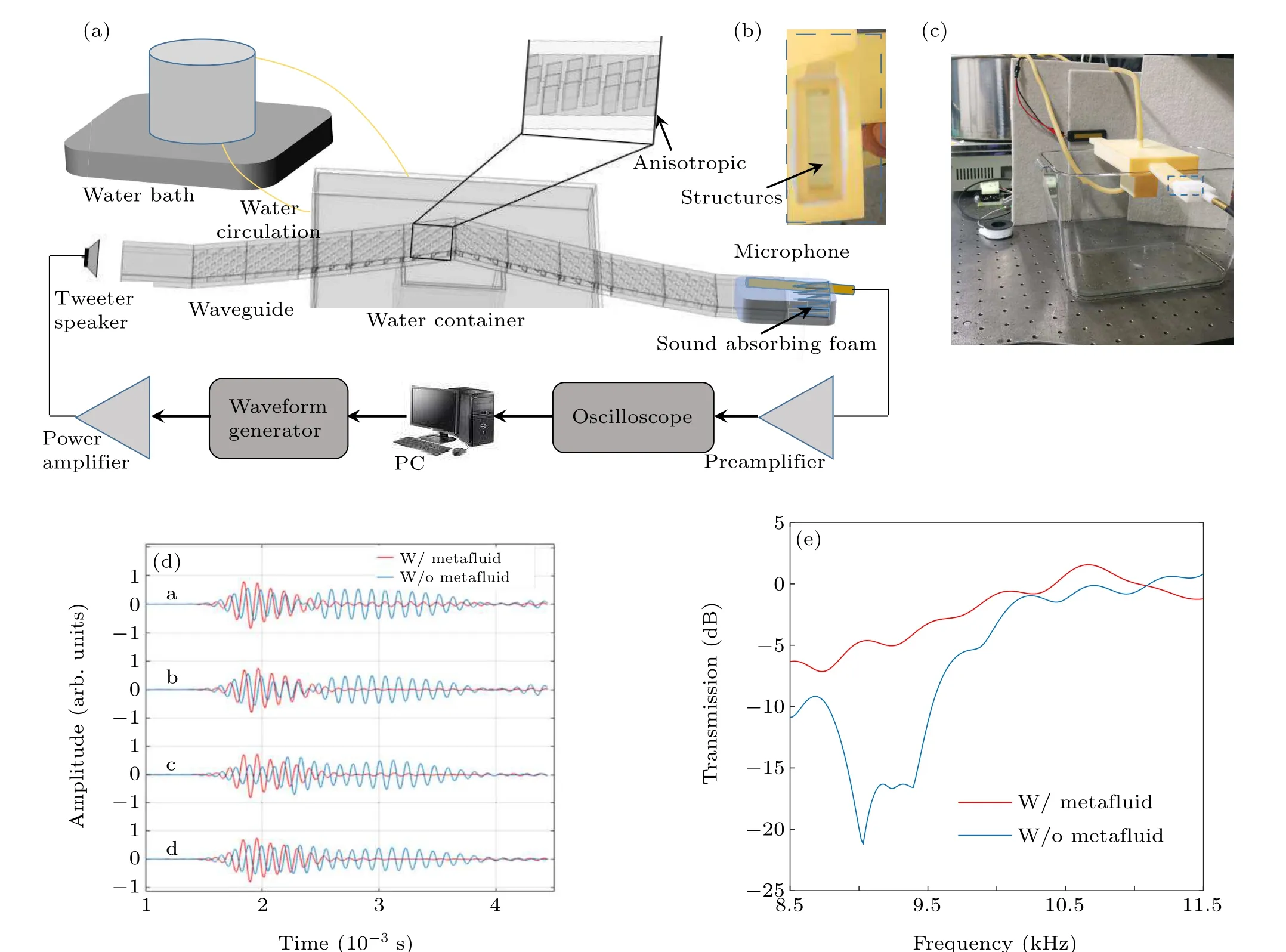
Fig. 6. (a) Scheme of the experimental setup; (b) photo of the anisotropic structures and (c) setup; (d) measured signals at different positions of the bent waveguide filled with air(blue),and filled with the metafluid(red);(e)averaged spectral response calculated from the measured time-domain signals.
4. Conclusion and perspectives
In conclusion, we analyzed the scattering behavior of anisotropic subwavelength structures,and designed and experimentally implemented a sound-transparent metafluid by arranging the highly anisotropic structures in a bent waveguide.All the effective acoustic parameters of the medium were independently modulated by tuning the geometry of the anisotropic unit and the temperature distribution. Abnormal transmission of sound pulses in this sound-transparent metafluid was observed, showing that a 9 kHz–11 kHz wave can be guided along a bent path nearly uninfluenced with negligible scattering compared with the bent waveguide only filled with air.The ability to guide sound waves along a given path makes this design of practical value in applications such as sound wave steering and invisibility.
Acknowledgments
Project supported by the National Natural Science Foundation of China (Grant Nos. 11974186, 11604153, and 61975080), the Natural Science Foundation of Jiangsu Province,China(Grant Nos.BK20160818 and BK20200070),and the Open Research Foundation of Key Laboratory of Modern Acoustics,Ministry of Education.

- Chinese Physics B的其它文章
- Magnetic properties of oxides and silicon single crystals
- Non-universal Fermi polaron in quasi two-dimensional quantum gases
- Purification in entanglement distribution with deep quantum neural network
- New insight into the mechanism of DNA polymerase I revealed by single-molecule FRET studies of Klenow fragment
- A 4×4 metal-semiconductor-metal rectangular deep-ultraviolet detector array of Ga2O3 photoconductor with high photo response
- Wake-up effect in Hf0.4Zr0.6O2 ferroelectric thin-film capacitors under a cycling electric field