Analysis of force and leakage in water hydraulic motor’s piston pairs①
2022-10-22 02:24:12WANGZhiqiang王志強DAIZejunLIXinglinHEWenGAODianrong
High Technology Letters 2022年3期
WANG Zhiqiang(王志強), DAI Zejun, LI Xinglin, HE Wen, GAO Dianrong
(*School of Mechanical Engineering, Hangzhou Dianzi University, Hangzhou 310018, P.R.China)
(**School of Mechanical Engineering, Zhejiang University, Hangzhou 310058, P.R.China)
(***Post-Doctoral Research Center, Hangzhou Bearing Test&Research Center Co. Ltd., Hangzhou 310022, P.R.China)
(****School of Mechanical Engineering, Yanshan University, Qinhuangdao 066004, P.R.China)
Abstract The positive pressure between pistonwall and piston hole of inner curve water hydraulic motor’s piston pairs is analyzed. The flow field of the piston pairs is numerically calculated and analyzed by the use of computational fluid dynamics method. The pressure and velocity distribution of flow field at different clearance is analyzed in the paper. The results show that when the clearance is 4-8 μm,with the increase of clearance,the negative pressure and the velocity of piston chamber decrease significantly, the velocity and leakage flow of the clearance increase. However, when the clearance is 10 μm, the negative pressure and the velocity of plunger chamber increase suddenly. By comprehensive analysis, the cylinder annular clearance should be controlled to be near 8 μm.
Key words: water hydraulic motor, piston pairs, clearance, leakage flow, numerical simulation
0 Introduction
In recent years, with the attention increasingly given to environmental pollution, water will become the most popular pressure medium instead of oil. So water hydraulic motor will have a wide developmental foreground as the execute component of hydraulic system.However, the special physical and chemical properties of water will bring a lot of problems in the research.Leakage is one of the major problems of them. In order to reduce the leakage flow and increase the volumetric efficiency of water hydraulic motor, international scholars make lots of work to research these problems. Friction measurement of water-based slippers was presented by Li and Hooke[1]of University of Birmingham in 1991. They found that the measured values are consistent with the clearances predicted using the analysis developed for oil-based slippers. The influence of piston clearance on leakage flow and torque of piston pair was analyzed, and the variation of leakage flow and torque of piston pair under different slot forms of piston was studied by Kumar et al.[2]. Lu et al.[3]studied the influence of rotating speed on the position and leakage of piston pair under high speed and high pressure.Wang[4]used the Matlab simulation analysis to research the influence of different piston cylinder bore diameter and different pressure on the leakage of piston pair. Meshkov et al.[5]studied the stress distribution of the piston in different contact states, and identified the most critical area of high stress.
Liu et al.[6]researched the leakage characteristics of water hydraulic piston pairs with multiple damping holes on the circumference of the piston. Ivantysynova and Baker[7]researched the influence of piston cylinder clearance shape on power loss, leakage and viscous friction, and predicted the pressure field and velocity field in the lubricating oil film. Schenk et al.[8]studied the pressure of piston pairs with different instantaneous displacement by computer simulation technology.Hu et al.[9]established an adaptive eccentric model to research the water film pressure distribution and leakage flow of piston pair. The leaking flow field of the piston sector considering the high press and high velocity were researched. Xu et al.[10]studied the effects of load pressure, inclined angle of swash plate and piston pair clearance on the performance of piston pairs by virtual prototyping techniques. Luo et al.[11]investigated the relationship between the leakage flow of piston and the angle of cylinder bore, then determined the clearance which made the minimum leakage between piston and cylinder bore.
Although, there have been many studies on force and leakage, they mainly focus on the study under oil lubrication. Limited information is available on the effect of different surface and geometries on flow characteristics between the friction pairs of low speed high torque hydraulic motor under seawater lubrication. To study the force and leakage properties of water hydraulic motor with ten piston pairs under seawater lubrication, the pressure and velocity distribution of flow field at different clearance were simulated by computational fluid dynamics method.
1 Structure features
1.1 Working principle
In this paper, the water hydraulic motor adopts the end face flow distribution mode. The structure of the water hydraulic motor is shown in Fig.1(a). The port block is embedded in the rear end cover, the left flow channel in the port block is connected with the inlet and outlet of the rear end cover, and the right flow channel is connected with the replaceable friction plate. The right end face of the friction plate is attached to the rotor, which completes the suction and drainage action of the piston by cooperating with the rotation of the rotor.
The distribution and structure of the piston modules in the rotor body of the water hydraulic motor are shown in Fig.1(b). The piston modules (roller and piston) are uniformly distributed circumferential in the ten piston holes of the rotor body. The pressure water in the flow channel of the rotor acts on the bottom of the piston, making the piston modules close to the inner curved surface of the stator, and at the same time,the modules are subjected to the reaction force from the stator. The tangential component force of the reaction force is transferred to the piston to form a unilateral pressure on the rotor[12], so that the water hydraulic motor turns.

Fig.1 Structure of internal curve type water hydraulic motor
To ensure the movement of the piston, it is necessary to ensure that there is a certain annular clearance between the piston and the piston hole. If the clearance is too big, the leakage of the water hydraulic motor will be greatly increased[13-15]. However, if the clearance is too small, it will be difficult to form a lubricating water film, making a direct contact between the piston and the rotor body which averts the wear and vibration[15-17]. Therefore, the piston pair clearance has an important effect on the performance of water hydraulic motor.
1.2 Materials and specimens
In order to explore the influence of force and leakage on the flow performance of the piston pairs better,the research was carried out on the basis of selecting the optimum matching material. The piston material is made of 316L stainless steel. The steel, which has excellent pitting corrosion resistance and could be safely used in halogen ion environment such as Chloride ion,is usually used in marine environment. The rotor is made of carbon-fifiber-reinforced polyetheretherketone(CFRPEEK), with low friction coefficient, excellent mechanical and corrosion resistance, and can be used in marine environment. The polyetheretherketone(PEEK)of CFRPEEK is white powder with average particle size of 10 μm and density of 1.32 g/cm3. The reinforcements are short-cut carbon fibers with diameter of 7 μm,density of 1.75 g/cm3, tensile strength of 3.5 GPa and tensile modulus of 228 GPa.
2 Force analysis of piston pairs
In order to study the friction of piston pair, the force magnitude of friction can not be ignored[18-20].For convenience of analysis and calculation, it is assumed that there is no clearance between piston wall and piston hole, and the force of the piston pair is ignored, such as the gravity of the piston pair and the impact force caused by the nonsteady flow in the piston cavity[20-22]. The force on the piston pair is shown in Fig.2. Suppose that the water supply pressure at the bottom of the piston isNpand the pressure on the roller reacted by the inner curved surface of stator isN.
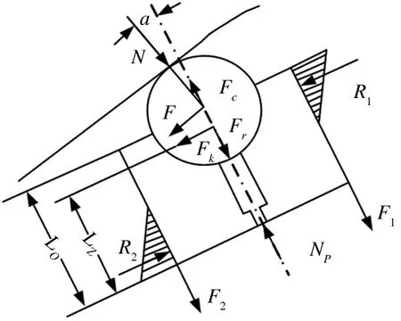
Fig.2 Force diagram of the piston pairs
LetFbe the moment of couple which equivalents to the center of the roller caused by friction, so there is


wherevis velocity of relative movement between piston wall and piston hole.
To calculateR1andR2, the positive pressure on piston wall and piston hole, supposing the length ofR1andR2acting on the piston wall areL1andL2,and supposing the stresses of piston due to elastic deformation areδ′andδ″,there are

The force between piston wall and piston hole can be further decomposed by the uniformly distributed force along the contact length(δN) and the force of two congruent triangles on the centrosymmetric distribution of the contact length(δM).The Fig.3 shows thatδMis used to balance the torque introduced byδN.

Fig.3 Stress decomposition diagram of piston pair
Soδ′andδ″can be further rewritten as
δ′=δM+δN(9)
δ″=δM-δN(10)
By using the forceN,F,Fkinvolved in Fig.3,the expressions of tangential force(Nx) and equivalent torque(M) of the piston pair can be derived according to the torque equilibrium equation and the force equilibrium equation. So there are
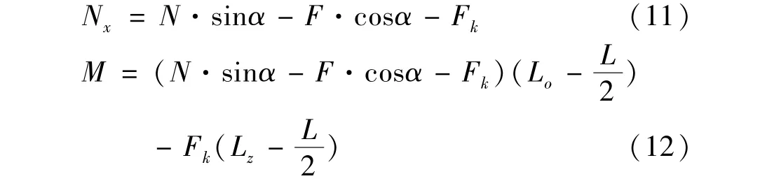
whereLois the distance from the center of the roller to the bottom of piston;Lis the contact length between piston wall and piston hole;Lzis the distance from the centroid of the piston module to the bottom of piston.
The resultant positive press stress corresponding toNxisδN,which can be derived as

Due to the stress triangles distributed on both sides of the piston,δ′andδ″are similar triangles, there is

According to the specific structure size of the hydraulic motor, Fig.4 shows the relationship between pressure angleαand the positive pressureR1andR2when the motor speed is 1500 r/min, whereαis 0 -30 °,R1andR2are 0 -2500 N.

Fig.4 The change of positive pressure with pressure angle
From Fig.4, it can be seen that the positive pressureR1andR2will both increase with the increase of pressure angleα.The friction between the piston wall and piston hole will increase with the positive pressureR1andR2,resulting in the decrease of the width of cylinder annular clearance and its leakage flow.
3 Leakage flow analysis of piston pairs
Fig.5 shows a picture of concentric clearance of piston and rotor. Setting the diameter of the piston asd,clearance ash,h <<d,then the annular clearance expanded along the length direction is considered as the same as a plain plate clearance. So the flow rate equation in concentric annular orifice can be obtained as[23-25]

where πdis circumference of piston, which is the same as the width of plain plate clearance,d=20 mm;Δpis a differential pressure of clearance, 10 MPa;Lis the length of clearance,13.15 mm;μis kinetic viscosity of fluids,μ=1.005 ×10⁻³pa·s for water,μ=44.2 ×10⁻³Pa·s for hydraulic oil.

Fig.5 The clearance of piston and rotor
Substituting available data into Eq.(25), the leakage flow of cylinder annular clearance of pistons and rotor can be got, as shown in Table 1. In those two cases, the change of leakage flow with clearance is shown in Fig.6.ter or hydraulic oil. From Fig.6, it can be seen that the leakage flow will increase significantly with the increase of clearance when the medium is water. Table 1 shows the comparison of leakage flow of cylinder annular clearance in different medium. It can be seen from the table, when the medium is water, leakage flow rate is about 40 -50 times of hydraulic oil with the same clearance. So the cylinder annular clearance of piston pairs should not be too large or it will greatly reduce the volumetric efficiency of water hydraulic motor.

Fig.6 The change of leakage flow with clearance

Table 1 The comparison of leakage flow of clearance in different medium
4 Numerical simulation of flow field of piston
4.1 Geometric modelling and meshing
A geometry model of piston pairs flow channel is established by using computational fluid dynamics (CFD)pre-processing software Gambit. Fig.7 shows the whole flow channel model. The inlet of model is the bottom of the piston. The outlet of model has two parts: the outlet of cylinder annular clearance (outlet 1) and the interior clearance of piston (outlet 2).

Fig.7 The flow channel of piston pairs
4.2 Setting of the boundary conditions
In this simulation ,water is adopted as the fluid medium. When its operating temperature is 20 ℃, the density is 998.2 kg/m3and the kinetic viscosity is 1.005 ×10⁻³Pa·s.
(1) Inlet boundary conditions
The boundary condition in the simulation is given according to the actual working condition. The rated pressure of the motor is 10 MPa, so the given inlet boundary condition is pressure inlet, and the pressure value is 10 MPa.
(2) Outlet boundary conditions
The outlet of the motor is set as the pressure outlet,and the outlet pressure value is 0 MPa. The water film between the piston and roller has leakage, so the side of the water film is set as the pressure outlet,and the pressure of outlet 1 and outlet 2 are 0 MPa.
(3) Wall boundary conditions
Generally,when doing static analysis, the interface between fluid and solid is static by default. For viscous fluid,its viscosity makes it adhere to the solid surface,and the outer most wall should move with the solid surface at the same speed without sliding. Therefore, the wall motion should be taken into account when setting the wall boundary of the motor.
4.3 CFD simulation and analysis
Fig.8 shows the change of pressure in cylinder annular clearance. From the figure,it can be seen that the pressure distribution remains largely unchanged with the increase of clearance,and the pressure along the axis direction of piston reduces gradually. Besides,the pressure remains constant at the same height.
Fig.9 shows the pressure contour plot of piston pairs inYOZplane. It can be seen from Fig.9 that the both sides of damping hole start to have pressure loss,and the pressure loss is constantly moving closer to the inlet of cylinder annular clearance. But the phenomenon will disappear when the clearance is 10 μm. From the pressure contour plot,it was also found that the negative pressure of piston chamber decreases with the increase of clearance, but the negative pressure has increasing tendency when the clearance is 10 μm. The higher the negative pressure,the easier it is to case cavitation. So the minimum negative pressure of clearance is the best.

Fig.8 The three-dimensional flow field pressure contour

Fig.9 The pressure of piston pairs in YOZ plane
Fig.10 shows the velocity contour plot of piston pairs inYOZplane. From the velocity contour plot, it can be seen that the location of the maximum flow velocity is at the outlet of damping hole,and the maximum flow velocity of piston chamber decreases significantly with the increase of cylinder annular clearance. However,the maximum flow velocity and the flow velocity in the inlet of cylinder annular clearance will increase suddenly when the clearance is 10 μm. This means the flow velocity of piston chamber is greatly affected by clearance.

Fig.10 The velocity of piston pairs in YOZ plane
The change curves of pressure and velocity in axis direction of piston at different clearance are shown in Fig.11 and Fig.12. Through the pictures,it can be seen that the negative pressure and velocity of piston chamber are the minimum when the clearance is 8 μm. And the maximum negative pressure of piston chamber is obtained when the clearance is 4 μm,the maximum velocity is obtained when the clearance is 10 μm.
Fig.13 shows the change of velocity with the length of cylinder annular clearance. It can be seen from the figure,in any case, the flow velocity will keep stable at a certain value with the increase of length,but the flow velocity will reduce with the decrease of clearance.
The leakage flow of cylinder annular clearance and interior clearance can also be got by CFD numerical simulation,as shown in Table 2. It can be seen from the table that the leakage flow of cylinder annular clearance goes up with the increase of clearance, and the leakage flow of interior clearance first goes down and then increase with the increase of clearance, and the minimumleakage flow of interior clearance was obtained when clearance is 8 μm. So the total leakage flow of piston pairs is the minimum when the clearance is 8 μm.

Fig.11 Pressure in axis direction of piston

Fig.12 Velocity in axis direction of piston

Fig.13 Velocity curve of cylinder annular clearance

Table 2 The leakage flow of piston pairs
5 Conclusion
(1) CFD simulation results show that the pressure of cylinder annular clearance goes down with height in different clearance. Besides, the pressure remains constant at the same height. This means fluid flow obeys the law of laminar flow. Moreover, the results show that with the decrease of clearance, the velocity and leakage flow of the cylinder annular clearance will reduce,and the velocity will keep at a certain value.
(2) By analyzing the pressure contour,velocity contour and total leakage flow of piston pairs, the velocity and the negative pressure of piston chamber are the minimum which will reduce the possibility of occurrence of cavitation and water hammer, and the total leakage flow of piston pairs is also minimum when the clearance is 8 μm. So the clearance should be controlled to be approximate 8 μm.
(3) Under different clearance widths, comparing Table 2 with Table 1 shows that the results of CFD numerical simulation are larger than theoretical calculation.This is because the inertia term is not considered in theoretical calculation,while CFD simulation is more comprehensive. From this point of view,CFD calculation results are more reliable.
 High Technology Letters2022年3期
- High Technology Letters的其它文章
- Numerical investigation on damping coefficient of the integral squeeze film damper①
- LDNet: structure-focused lane detection based on line deformation①
- Multi-attention fusion and weighted class representation for few-shot classification①
- Deep learning-based time-varying channel estimation with basis expansion model for MIMO-OFDM system①
- Research on will-dimension SIFT algorithms for multi-attitude face recognition①
- Deep learning based curb detection with Lidar①