Discussion on interface deformation and liquid breakup mechanism in vapor–liquid two-phase flow
2023-10-11 07:55:44XiangAn安祥BoDong董波YaJinZhang張雅瑾andXunZhou周訓
Chinese Physics B 2023年9期
Xiang An(安祥), Bo Dong(董波), Ya-Jin Zhang(張雅瑾), and Xun Zhou(周訓)
1School of Naval Architecture and Maritime,Zhejiang Ocean University,Zhoushan 316022,China
2Key Laboratory of Ocean Energy Utilization and Energy Conservation of Ministry of Education,School of Energy and Power Engineering,Dalian University of Technology,Dalian 116024,China
3Institute of Refrigeration and Air Conditioning Technology,Henan University of Science and Technology,Luoyang 471003,China
Keywords: liquid breakup,lattice Boltzmann method,capillary instability,end-pinching mechanism
1.Introduction
Interface deformation and liquid breakup are common in various natural and industrial vapor–liquid two-phase phenomena, such as raindrop falling,[1]inkjet printing,[2]and fuel atomization.[3]Distinguishing the vapor–liquid interface deformation and liquid breakup mechanisms is significant and helpful for understanding the interface evolution and fluid movement.According to Eggers and Villermaux,[4]the vapor–liquid interface is either dominated by the Rayleigh–Taylor instability (RTI) and the Kelvin–Helmholtz instability(KHI)or controlled by the Rayleigh mode where the capillary instability is predominant.
On the one hand,the RTI and KHI are investigated from different influencing factors or presented as model validation examples.Li and Umemura[5]studied the large interface deformation and spike formation mechanism aroused by the RTI at a large Atwood number.Liuet al.[6]explained the liquid ligament generation from the interface in the RTI.Kim K S and Kim M H[7]simulated the KHI in a multiphase system with multiple interfaces by using a moving particle semi-implicit method.Daiet al.[8]derived the analytical formulas for the KHI of two superposed finite-thickness fluid layers with the magnetic field effect taken into consideration, and found that the effect of thickness is more obvious when the magnetic field intensity is weak.Zhouet al.[9]analyzed the RTI and the KHI in wide ranges of density ratio, viscosity ratio, and Reynolds (Re) number adopting the lattice Boltzmann (LB)method.[10,11]Chenet al.[12]investigated the effects of initial perturbations on the RTI, KHI, and the coupled RT-KHI system by using a multiple-relaxation-time discrete Boltzmann model.Besides, some studies[13–16]also simulated these two instability phenomena and validated the mathematical model via them.In general, the RTI and KHI depict the deformation of the vapor–liquid interface based on the above research.On the other hand, capillary instability has been reported in studies of the liquid jet and droplet collisions.The liquid jet breakup process was carried out by Delteilet al.,[17]and the growth of the capillary instability was simulated.They pointed out that the amplification of the capillary instability induces the liquid jet breakup,and the breakup of the liquid sheet into droplets is due to a coupling between the capillary instability and KHI.Conget al.[18]investigated the binary unequal-sized droplet collision under different Weber(We)numbers and impact parameters.They revealed that capillary instability can be observed on the liquid ligament at large impact parameters.Similarly, Chaitanyaet al.[19]studied the oblique collision of two unequal-sized liquid droplets and found that the end-pinching mechanism is operational in the head-on droplet collision and the capillary instability is responsible for the liquid ligament breakup at large impact parameters.Anet al.[20]simulated the binary droplet collision process with different angles,and their results showed that the liquid back-flow phenomenon is caused by the end-pinching mechanism, which further leads to the capillary instability on the liquid ligament.
In the above studies on two-phase flow, the fluid instability mechanisms include the RTI,the KHI,the capillary instability, and the end-pinching mechanism.Different mechanisms describe the fluid movement from different perspectives,as previously mentioned,the RTI and KHI are two instability mechanisms characterizing the vapor–liquid phase interface deformation, while, the capillary instability and endpinching mechanism are difficult to recognize and easily confused with the former.Adopted in this work is a threedimensional(3D)phase-field-based LB model[21]to simulate three benchmark cases, analyze the fluid movement based on the capillary instability and the end-pinching mechanism,and clarify the stances of different mechanisms in vapor–liquid two-phase flow.The rest of this paper is organized as follows.The 3D phase-field-based LB model is elaborated in Section 2.Three benchmark cases are simulated and the relevant fluid movement mechanisms are discussed in Section 3.A brief summary is presented in Section 4.
2.Mathematical method
As an increasingly popular fluid dynamics method, the LB method has been used to investigate different phenomena, such as bubble collapse,[22]micro-scale fluid flow,[23]and combustion and detonation.[24]There are also some reviews[25,26]expatiating this method, in which different schemes and models are introduced, including the phasefield-based LB model.This model was developed in the 2000s.[27,28]Some studies[29,30]used two sets of LB equations to recover the Cahn–Hilliard equation for interface tracking and the incompressible Navier–Stokes equations for hydrodynamic properties.However, the Allen–Cahn-based LB model was pointed out to have higher numerical accuracy and stability in solving the index parameter than the Cahn–Hilliard-based LB model.[31]Following this point,the singlerelaxation-time (SRT) operator form[32]and the multiplerelaxation-time(MRT)operator form[21]for the Allen–Cahnbased LB model were developed.This MRT phase-field-based LB model is presented in the following.
In the model,the conservative Allen–Cahn equation is the macroscopic equation to capture the interface,which is written as[33,34]
whereφis the order parameter characterizing the interface,Mis the mobility, andλis a function ofφ.In addition,nis the unit vector normal to the interface, anduis the velocity,which is governed by the following incompressible Navier–Stokes equations[14]
wherepis the hydrodynamic pressure andFis the total force.
In this LB model,two sets of evolution equations are designed to solve Eqs.(1)–(3),respectively,
wherefandgare the particle distribution functions,feqandgeqare the corresponding equilibrium distribution functions,and ^Fiand ^Giare the forcing distribution functions.[35–37]The D3Q7 lattice model and the D3Q15 lattice model are adopted in Eqs.(4)and(5),respectively,andMD3Q7andMD3Q150are the corresponding transformation matrices,
SfandSgare the diagonal relaxation matrices,which can be written as
By premultiplying the corresponding transformation matrices in Eqs.(4) and (5), and multiplying the particle distribution functions and the forcing distribution functions with the corresponding transformation matrices in parentheses on the righthand sides,the following equations are obtained:
wheremf=MD3Q7·fandmg=MD3Q15·gare the particle distribution functions in moment space.Equations (12)and(13)represent the collision process in moment space.The equilibrium distribution functions and the forcing distribution functions can be obtained after some algebraic operations,
In this phase-field-based LB model, the order parameterφis calculated by particle distribution functionfas
Then, the density, viscosity, velocity, and pressure can be given,respectively,by
where the subscripts l and v represent the liquid phase and the vapor phase.ei,cs,andωiare the discrete velocity,the lattice sound speed, and the weighting coefficient in D3Q15 lattice model,respectively,andsi(u)can be calculated from[21]
3.Numerical results and discussions
Simulated in this section are three benchmark cases including droplet impact on a solid surface,breakup of a liquid ligament, and binary droplet collision and breakup, by using the above numerical model,and the liquid phase deformation and breakup mechanisms are also discussed here.
3.1.Droplet impact on a solid surface
The process of droplet impacting on a solid surface is simulated and the numerical results are compared with the experimental data of Donget al.in this subsection.[38]Two dimensionless parameters ofRenumber andWenumber are used to characterize the impact process,which are calculated as
whereU0is the initial droplet velocity,D0is the initial droplet diameter,νlandρlare the viscosity and density of the liquid phase,respectively,σis the surface tension coefficient.In the simulation,the computational domain size is 200×200×100 in lattice unit in thex,y, andzdirections.The periodic boundary is adopted in thexandydirections,and the halfway bounce-back scheme is applied to the solid surface, which is perpendicular to thezdirection.In the initialization,the order parameter profile is
whereRis the droplet radius andWis the interface width.The initial velocity is set as
According to Donget al.,[38]the system consists of a droplet and an ambient vapor phase on the solid surface.The contact angles are set as 31°and 107°.The droplet diameter is 48.8 μm, and its velocity is 4.36 m/s.The dimensionless parametersRenumber andWenumber are 238.0 and 12.8, respectively.In the simulation,the initial droplet radius and velocity are 25.0 and 0.05 in lattice unit,respectively.According to the droplet diameter in physical unit and lattice unit, the spatial resolution Δlcan be calculated to be 0.976 μm.Then,the temporal resolution can be obtained to be 0.011193 μs by Δt=vl·Δl/vp,wherevlandvpare the droplet velocity in lattice unit and physical unit, respectively.Besides, the density ratio of the liquid phase to the vapor phase is 844.0,the kinematic viscosity ratio of the vapor phase to the liquid phase is 34.8,the surface tension coefficient is 0.098,and the interface width is 4.0.
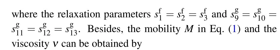
The interface evolutions in the process of droplet impacting on a solid surface are presented in Fig.1.The changes of the droplet lateral spreading ratioD*,namely the droplet size parallel to the solid surface and the droplet heightH*on the droplet center line are extracted for quantitative comparisons,as shown in Fig.2,which are normalized by the initial droplet diameterD0.Table 1 lists the relative errors between the numerical results and experimental data in the process of droplet impacting on a solid surface, corresponding to the four cases in Fig.2.The error values are calculated at eight time points for each case,and their average values are also given.As can be seen from the table,when the contact angle is 31°,the numerical results are closer to the experimental data than when the contact angle is 107°.According to the average errors,the values are within 6%for the four cases.Besides,there are differences between the numerical results and experimental data,especially the droplet heights greatly differ from each other in a range from 13 μs to 25 μs as shown in Fig.2(a).As can be seen from the figure, before the first turning point of the droplet height at about 13 μs,the droplet lateral spreading ratio obtained numerically is smaller than the experimental data generally,and the droplet height obtained numerically is larger than the experimental data.One can see that the droplet is not susceptible to spread after the impact.After, there is a distinct increase of the droplet height,namely,the droplet shows strong contractility.Accordingly,it can be inferred that a large surface tension,which makes it difficult for the droplet to expand and easy to contract, is probably the main factor causing the numerical error,especially for the turning point within 13 μs to 25 μs.
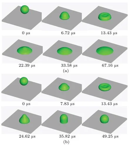
Fig.1.Interface evolutions in the process of droplet impacting on a solid surface with contact angle being(a)31° and(b)107°.
Combining Figs.1 and 2, when the droplet impacts on the hydrophilic surface, the contact area between them increases continuously and rapidly within 10 μs.At this stage,the droplet morphology mainly depends on the kinetic energy of droplet.After 13.43 μs, the droplet spreads over the solid surface gradually.The surface tension and the wetting condition determine the droplet morphology,and the liquid phase covers the solid surface with an umbrella shape eventually.For the hydrophobic solid surface,the interface evolution is similar to that on the hydrophilic surface before 13 μs.However,after that, the contact area between the droplet and the solid surface shrinks gradually, and the liquid phase is attached to the solid surface as a hemisphere eventually after some oscillations.In this stage, the surface tension plays a leading role in the contraction of the liquid phase.In the process of droplet impacting on a solid surface, the liquid phase only deforms without breakup, the droplet kinetic energy, surface tension,and the wetting condition are the determinants.
Fig.2.Variations of lateral spreading ratio D*and droplet height H*with time in the process of droplet impacting on solid surface with contact angle being(a)31° and(b)107°.
Table 1.Relative errors between numerical results and experimental data in the process of droplet impacting on a solid surface.
3.2.Breakup of liquid ligament
The breakup of a liquid ligament is an interesting phenomenon, and it is helpful to understand the liquid breakup mechanism.[39]Rayleigh[40]analyzed the stability of a liquid ligament and indicated that the liquid ligament is unstable if the disturbance wavelengthλon the liquid ligament is greater than the perimeter 2πRof the liquid ligament.Namely,if the wave numberk=2πR/λis less than 1,the liquid ligament is unstable.
In the simulation,the computational domain size isLX×λ×LZin thex,y, andzdirections, and the periodic boundary is applied to all directions.In the initialization, the order parameter distributes as follows:
whereRis the initial radius of the liquid ligament,which is set as 15.0 in the simulation.The interface widthWis set as 4.0,andDis the disturbance function.The computational domain sizeLXandLZin thexandzdirections are set as 90,and the values of disturbance wavelengthλare set as 230, 300, and 400 in three cases, respectively.Correspondingly, the values of wave numberkare 0.41,0.31,and 0.24.Besides,the density ratios between the liquid phase and the vapor phase are set as 100 and 10,and the surface tension coefficient is 0.15.
Figure 3 gives the liquid ligament breakup process at the liquid/vapor density ratios of 10 and 100 when the wave number is 0.31.The time steptis normalized intot*=Initially, the liquid ligament begins to converge gradually into both ends under the action of surface tension and disturbance.As the liquid ligament in the middle becomes thin and the liquid accumulates at both ends,the breakup occurs at the joint between the liquid ligament and the hemispheroid.This breakup is dominated by the endpinching mechanism,[41,42]which describes the liquid phase back-flow phenomena at the joints of hemispheroids and the liquid ligament.[20]After the breakup, the liquid phase is divided into the droplet and the liquid ligament in the middle.The former becomes a stable sphere eventually after some oscillations, namely the main droplet, and the latter contracts rapidly into a small droplet due to surface tension,namely the satellite droplet.The liquid ligament fracture is the detail of the liquid breakup,and its mechanism refers to the essence of the liquid breakup.Namely,the end-pinching mechanism can be considered as the immanent cause of other liquid breakup mechanisms, such as capillary instability.Besides, by comparing the interface evolutions in Fig.3(a) and with those in Fig.3(b), one can see that it takes longer time for the liquid ligament to break at a density ratio of 100 than at a density ratio of 10.That is to say,the liquid breakup process is closely related to the liquid/vapor density ratio, and a large density ratio makes it difficult for the liquid to breakup.
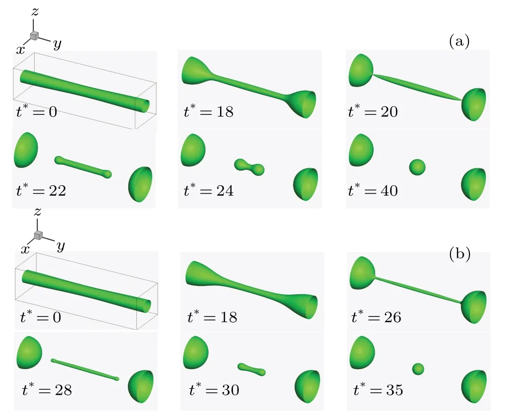
Fig.3.Liquid ligament breakup process with wave number k being 0.31 and liquid/vapor density ratio being(a)10 and(b)100.
In previous studies, the relationships between the main droplet radius,the satellite droplet radius,and the wave number were investigated numerically,[43]theoretically,[44]and experimentally.[45]Figure 4 depicts the main droplet radii and the satellite droplet radii at three different wave numbers, as well as the relevant data from previous studies.The vertical coordinateR*is normalized by the initial radius of the liquid ligamentR.As can be seen from the figure, the main droplet radius and the satellite droplet radius decrease as the wave number increases, and the liquid phase is allocated much to the main droplet rather than the satellite droplet when the density ratio is 100.In the figure, the simulation results of the satellite droplet radius are different from previous data, especially in the case of a density ratio of 100.The errors may be caused by spontaneous shrinkage[46]and measurement errors in the case of a small droplet.
3.3.Binary droplet collision and breakup
The collision process and breakup process of binary droplets exist widely in natural and industrial phenomena.In general, the collision process between binary droplets is divided into five regimes: coalescence, bouncing, coalescence with major deformation, head-on separation, and off-center separation.[47]It is worth mentioning that in the study of shear-driven two colliding motions of binary double emulsion droplets,[48,49]two typical colliding motions of passing-over motion and reversing motion are observed experimentally and numerically,in which the reversing motion,namely the bouncing regime, has never been observed in previous numerical studies.As theRenumber and theWenumber increase, the droplet breakup occurs instead of coalescence or separation.The binary droplet collision and breakup process are simulated and the results are also qualitatively compared with the experimental results of Panet al.in this subsection.[50]
The binary droplet collision process is characterized by theRenumber and theWenumber
whereRis the droplet radius,Uis the relative velocity between the two droplets,ρlandνlare the liquid density and kinematic viscosity,andσis the surface tension coefficient.Figure 5 displays the binary collision process atRenumber andWenumber of 1720 and 58, respectively.The computational domain size is 300, 250, 250 in thex,y, andzdirections.Figures 6 and 7 give the breakup processes in binary droplet collision atRe=4690,We=280,andRe=6650,We=878,respectively.For these two cases,the computational domain sizes are 250,300,300 in thex,y,andzdirections.In these three cases,the periodic boundary scheme is applied to all directions.In each of Figs.5–7,panel(a)shows the present numerical results,and panel(b)displays the experimental results of Panet al.[50]
In Fig.6, a round phase structure and a flat liquid phase structure appear after the impact.Specifically, the outermost secondary droplets do not break away immediately from the liquid phase structure,even though crannies between the outermost secondary droplets and the liquid phase structure appear.Then,the entire liquid phase structure disintegrates into many secondary droplets due to the contraction caused by surface tension, namely the capillary instability on the liquid phase structure.These secondary droplets have no kinetic energy, thus in this process, the initial droplet kinetic energy determines the deformation of the liquid phase only, and the capillary instability on the liquid phase structure is the mechanism of driving the liquid breakup and secondary droplet formation.In the end,the liquid phase exists entirely in the form of irregular secondary droplets.In the process of liquid phase structure disintegration,the end-pinching mechanism works at each breakup point,resulting in capillary instability on the liquid phase structure.The end-pinching mechanism is the fundamental mechanism for the liquid breakup and the immanent cause of the capillary instability.
Unlike the scenario in Fig.6, the outermost secondary droplets are produced and “fly away” before the liquid phase structure becomes flat completely in Fig.7.These secondary droplets have their kinetic energy, which can only be derived from the initial droplet kinetic energy.When the liquid phase structure becomes flat completely, the residual inner liquid phase decomposes due to the end-pinching mechanism and the capillary instability,which is the same as that in Fig.6.In the whole process, the produced secondary droplets are smaller than those in Fig.6, the initial droplet kinetic energy and the capillary instability both contribute to the liquid breakup and the secondary droplet production.
Combining the point of Eggers and Villermaux,[4]and the above discussion,one can conclude that RTI,KHI,and capillary instability are the instability mechanisms of the vapor–liquid phase interface.However, it should be pointed out clearly that RTI and KHI are the interface deformation mechanisms as mentioned in the Introduction,and the capillary instability is the driving mechanism of the liquid phase disintegration and the secondary droplet production when theWenumber is large,by comparing Fig.5 with Figs.6 and 7.
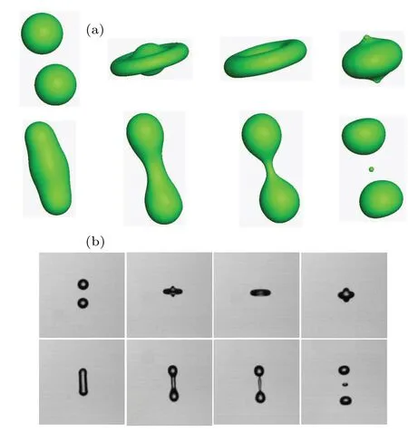
Fig.5.Binary droplet collision process at Re = 1720 and We = 58: (a)present results and(b)experimental results
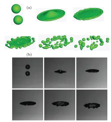
Fig.6.Binary droplet collision and breakup process at Re = 4690 and We=280: (a)present results and(b)experimental results.
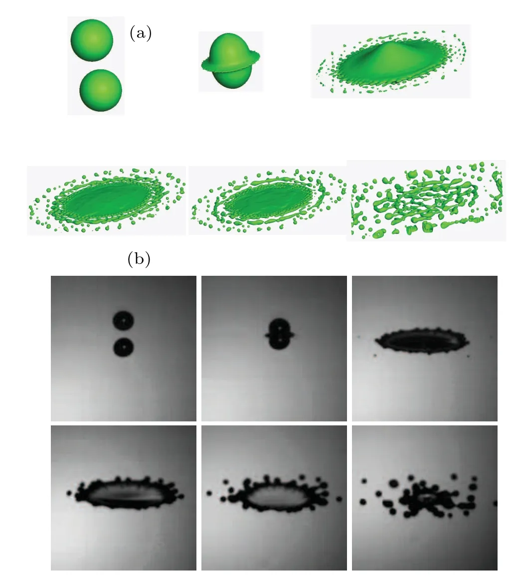
Fig.7.Binary droplet collision and breakup process at Re = 6650 and We=878: (a)present results and(b)experimental results.
4.Conclusions
A 3D phase-field-based LB model is adopted to simulate the droplet and liquid ligament dynamic behavior and analyze the interface deformation and liquid breakup mechanisms in this work.Based on previous studies and present analysis results, RTI, KHI, and capillary instability are triggered off by different vapor–liquid phase interface instability mechanisms, specifically speaking, RTI and KHI dominate the interface deformation and the capillary instability is driven by the liquid breakup and the secondary droplet production at a largeWenumber.As another liquid breakup mechanism, the end-pinching mechanism,which describes the back-flow phenomenon of the liquid phase, works at each breakup point,thus resulting in capillary instability on the liquid phase structure.In essence,it is the fundamental mechanism for the liquid breakup and the immanent cause of capillary instability.
Acknowledgements
Project supported by the National Natural Science Foundation of China (Grant No.51776031), the Fundamental Research Funds for Zhejiang Provincial Universities and Research Institutes, China, and the Key Project of Science and Technology Development of Henan Province, China (Grant No.222102220033).

- Chinese Physics B的其它文章
- Robustness of community networks against cascading failures with heterogeneous redistribution strategies
- Identifying multiple influential spreaders in complex networks based on spectral graph theory
- Self-similarity of complex networks under centrality-based node removal strategy
- Percolation transitions in edge-coupled interdependent networks with directed dependency links
- Important edge identification in complex networks based on local and global features
- Free running period affected by network structures of suprachiasmatic nucleus neurons exposed to constant light