Enhancing surface adhesion of polytetrafluoroethylene induced by two-step in-situ treatment with radiofrequency capacitively coupled Ar/Ar+CH4+NH3 plasma
2023-11-16 05:38:08MantingLU盧曼婷YiHE何弈XueLIU劉學JiaminHUANG黃嘉敏JiaweiZHANG張佳偉XiaopingMA馬曉萍andYuXIN辛煜
Plasma Science and Technology 2023年10期
Manting LU (盧曼婷), Yi HE (何弈), Xue LIU (劉學), Jiamin HUANG (黃嘉敏),Jiawei ZHANG (張佳偉), Xiaoping MA (馬曉萍) and Yu XIN (辛煜)
Jiangsu Key Laboratory of Thin Films,School of Physical Science and Technology, Soochow University,Suzhou 215006, People’s Republic of China
Abstract
Keywords: adhesion property, surface modification, capacitively coupled plasma,polytetrafluoroethylene
1.Introduction
Polytetrafluoroethylene (PTFE) has been used in various applications due to its excellent properties, such as wear resistance, acid and alkali resistance and thermal stability[1-4].The hydrophobicity and low surface tension of PTFE make it very difficult to bond with other materials, seriously limiting its scope of application [5, 6].Hence, various techniques have been used to modify PTFE to improve its surface activity and adhesion strength, such as chemical etching[7, 8], radiation-induced grafting [9], plasma treatment [10]and so on.Chemical etching,by destroying the C-F bonds of PTFE and connecting the functional groups using a sodium naphthalene solution, has become the most representative method.However, this causes environmental pollution and human injury.In comparison, the low-temperature plasma treatment is a good candidate and one of the most promising methods [11].
When electrons with enough energy obtained from the electric field collide with other particles in plasma, decomposition, adsorption, ionization, excitation and other reaction processes occur [12].Thus, the resultant active species in plasma not only have high chemical activity but also appropriate ion bombardment energy.The chemical structure and surface morphology of PTFE can be controlled by changing the discharge parameters of plasma.
Lee et al [13] treated PTFE with an Ar+ion beam andion beam, respectively.They found that the roughness and adhesion of PTFE treated with the Ar+ion beam in O2atmosphere were better than those with only theion beam.Generally, charges will always be accumulated on the insulating PTFE surface, and the formed potential due to the accumulated charges will decrease the ability of ion bombardment.Therefore, it is necessary for tungsten wire to emit electrons to neutralize the ion beam, which limits its application.Pachchigar et al [14] obtained a superhydrophobic structure when treating PTFE with Ar capacitively coupled plasma (CCP).Low-pressure O2plasma was used to treat PTFE to form a surface with a spherical structure,which was explained by the different etching rates, influenced by the orientation and size of the crystallites in the polymer substrates [10].Atmospheric pressure plasma treatment did not produce a textured structure on the PTFE surface due to the lack of effective ion bombardment[15].However,the surface etching could be improved with thermal assistance [16, 17].
Generally,the low surface tension of PTFE is determined by its surface nonpolar structure.Destroying the C-F bonds or grafting other non-fluorine groups on the surface may improve the surface tension[18,19].In the plasma discharge process, highly active H produced by H-containing gas can scavenge fluorine at the PTFE surface, thus enhancing the surface defluorination.Chen et al [20] used Ar, O2, He, H2and NH3plasmas to treat PTFE samples, respectively, and showed that the F/C ratio of the PTFE surface treated with H-containing plasma was always smaller than that with hydrogen-free plasma under the same conditions.Hai et al[21] reported that H-containing inductively coupled plasma can not only reduce the F/C ratio but also combine some active groups, such as -OH and -NH2, on the PTFE surface.The introduction of these polar groups contributes to the enhancement of the wettability of PTFE, beneficial to the improvement of the adhesion.Inagaki et al[22]treated PTFE with NH3plasma at high temperatures.The F/C was reduced to 0.29 at 150°C, and the adhesion strength with rubber reached 8.1 × 10³N m?1.
Although the surface can be defluorinated and combined with certain polar groups to improve the surface hydrophilicity,its service life cannot be maintained for a long time[23, 24].Zanini et al [10] studied the aging effect of PTFE under the treatment of O2plasma.Due to the rotation and migration of the polymer chain,the density of polar groups on the surface decreased over time, and the water contact angle of the sample gradually recovered to 150° after 30 days.For the sake of the service life of the treated samples, grafting acrylic acid, acrylamide and other organics on the PTFE surface was widely considered because the presence of an acrylic coating not only protects the PTFE surface from oxidation but also effectively prevents the rotation and migration of polymer chains.Additionally, the adhesion of PTFE can be improved by adding an acrylic coating with a large number of -COOH radicals, since a covalent bond is formed between these radicals and the epoxy group in epoxy resin [11, 25-31].Meanwhile, Hegemann et al found that using C2H4+CO2plasma to deposit a cross-linked layer on the surface of PTFE can also reduce the water contact angle and suppress the aging effect [32].
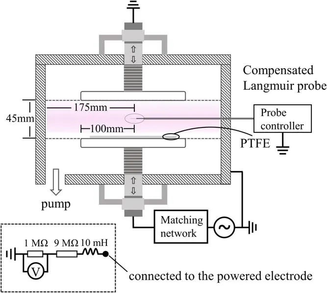
Figure 1.Schematic of the CCP apparatus equipped with Langmuir probe.
Inspired by the considerations mentioned above, we proposed a two-step in-situ strategy to form a PTFE surface with a hill-shaped microstructure and high surface free energy.The hill-shaped microstructure on the PTFE with a high specific surface area was prepared by controlling the parameters of Ar CCP, and subsequently, an a-CNx:H crosslinking layer was used to cover the hill-shaped microstructure of the PTFE by Ar+CH4+NH3CCP treatment.The crosslinking layer showed high surface free energy and possessed good adhesion to the PTFE substrate.Our two-step in-situ strategy not only lessens the processing procedure and time of treatment, but also greatly improves the stability and the adhesion ability of samples.
2.Experiment
In this experiment,PTFE with a thickness of 0.2 mm was cut into pieces of 50 × 50 mm2, cleaned with absolute alcohol,and dried at 60°C.
As shown in figure 1, the discharge chamber, made of stainless steel, is 300 mm in height and 350 mm in diameter.The distance between the two electrodes was set to 45 mm.The PTFE samples were placed on the bottom electrode,which was connected by a power supply (RSG-500) with a frequency of 13.56 MHz via an automatic matcher (SP-Ⅱ).The bias voltage was measured by a DC voltmeter,which was connected to the powered electrode via a 9 MΩ resistor.The Ar plasma was diagnosed by a compensated Langmuir probe(Hiden Analytical).Details can be found in other articles[33].
Before each experiment, the chamber was pumped to a background pressure lower than 5 × 10?3Pa.The total gas flow rate was set to be 80 sccm, the discharge power was set between 50 W and 150 W, and the pressure was set between 5.0 Pa and 12.0 Pa.In the two-step in-situ treatment, Ar plasma was used for the PTFE treatment for 8 min, and then the plasma was switched to Ar+NH3+CH4treatment for 5 min.During the plasma treatment, the chamber cannot be exposed to the air.The reason for choosing CH4and NH3can be attributed to the following points.Carbon atoms contain four unpaired electrons, while nitrogen atoms have three unpaired electrons, which can generate more cross-linked structures via the interaction of plasma and surface and thus improve the molecular bonding ability [34].Most importantly, rich H-containing plasma enhances defluorination,which is beneficial for surface hydrophilicity [20].
The adhesion strength tests were conducted with a tensile testing machine.After a special adhesive with a thickness of about 10 μm was brushed on an iron plate with 100 mesh sandblasting, the plasma-treated PTFE was covered on the iron plate and pressed with a pressure of 10 MPa at 150°C for an hour.After that, the machine peeled it away to obtain the adhesion strength.
The surface morphologies of the treated samples were examined using scanning electron microscopy(SEM,SU8100,Regulus) and atomic force microscopy (AFM, MFP-3D, Asylum Research), respectively.X-ray photoelectron spectroscopy(XPS,ESCALAB 250 XI,Thermo Fisher Scientific)was used to analyze the surface chemical composition of the treated samples.The water and diiodomethane contact angles of the treated samples were measured with a contact angle tester(JC2000DM) to calculate their surface free energy.
3.Results and discussion
3.1.Plasma diagnosis
In capacitively coupled discharges, electrons gain energy from the oscillating radiofrequency electric field and lose energy through collisions with background atoms, accompanied by reactions such as excitation, ionization, decomposition and so on.Due to the difference between electrons and ions in mass, a sheath with a certain thickness and negative bias forms between the bulk plasma and electrode.Under the influence of negative bias,ions entering the sheath will bombard the electrode.The negative bias can be expressed by the following equation [12]:
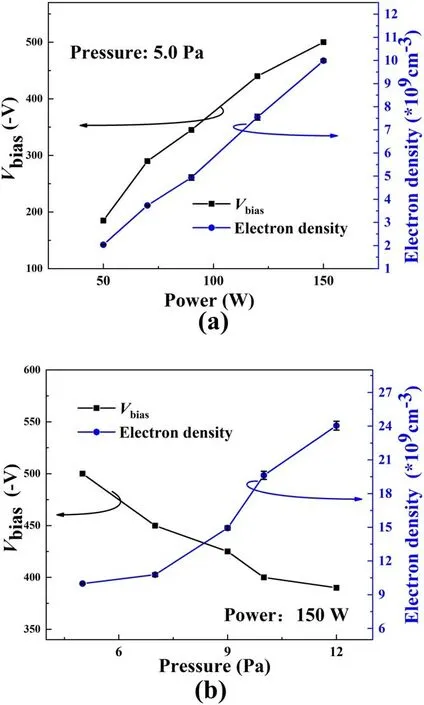
Figure 2.Electron density and bias voltage of Ar CCP with different(a) input powers and (b) gas pressures.
where Vrf, Te, m and M are the amplitude of the discharge voltage, the electron temperature, the electron mass and the ion mass, respectively.As shown in the equation, the bias depends on both Vrfand Te.Additionally,with the increasing discharge pressure, ions passing through the sheath will experience collisions and scatter with the background gas molecules and thus decrease its bombardment ability.Figure 2 shows the power and discharge pressure dependence of the electron density and bias voltage in Ar plasma.It can be found that the bias voltage increases linearly with the discharge power from 185 to 500 V, while the electron density goes from 2.0 × 10⁹to 10.0 × 109cm?3at a pressure of 5.0 Pa.Furthermore, figure 2(b) also shows that the electron density increases with the pressure, while the bias voltage decreases slightly due to ion scattering with background gas molecules for the power of 150 W.
3.2.Surface morphology of Ar-treated PTFE
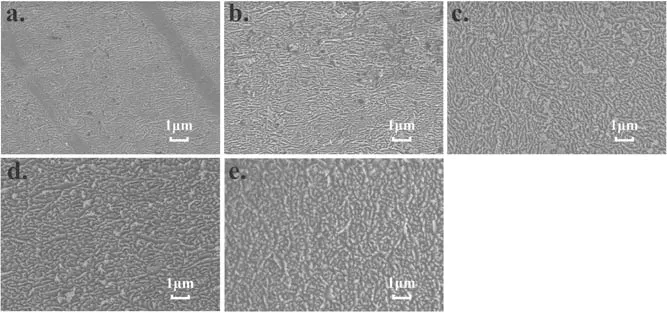
Figure 3.Surface morphology of PTFE treated by Ar CCP at 5.0 Pa with different powers: (a) 50 W, (b) 70 W, (c) 90 W, (d) 120 W,(e) 150 W.
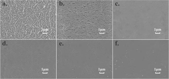
Figure 4.Surface morphology of PTFE treated by Ar CCP at 150 W with different gas pressures: (a) 5.0 Pa, (b) 6.0 Pa, (c) 7.0 Pa, (d)9.0 Pa, (e) 10.0 Pa, (f) 12.0 Pa.
Figure 3 shows the evolution of the surface morphology of PTFE with the input power ranging from 50 to 150 W at the pressure of 5.0 Pa.As is known,the ion energy increases with the input power.From figure 3,it can be found that the greater the input power, the clearer the microstructure on the PTFE surface.This indicates that the formed hill-shaped structure is actually induced by the ion bombardment, which is in accordance with a report from Pachchigar et al [14].This is also evidenced by figure 4 showing the dependence of the microstructure of PTFE on the discharge pressure.From figure 4, we see that with a discharge pressure larger than 5.0 Pa, the surface hill-shaped structure almost disappears.When the pressure is set to be 6.0 Pa,the treated surface looks like a net.The reason for this is attributed to the enhanced ion scattering with background gases with the increasing pressure, while the lateral ion energy will almost smooth out the formed microstructure but with a few holes on the surface,as seen in figures 4(c)-(f).
AFM was used to characterize the depth information of the PTFE surface microstructure treated by Ar CCP,including the specific surface area.As shown in figures 5(a)-(e), the measurement results agree with those of SEM.From the AFM measurements, we also find that the specific surface area and roughness of samples rise linearly with the discharge power,as shown in figure 5(f).The roughness changes from 17.65 to 105.6 nm with the discharge power,while the specific surface area increases from 1.07 to 2.18.For the discharge pressure influence,the roughness decreased dramatically from 105.6 to 55.92 nm,while the specific surface area decreased from 2.18 to 1.28,as shown in figure 6.This further indicates the role of ion bombardment on the surface microstructure formation.It is noteworthy that a high surface roughness and high specific surface area are helpful to the mechanical interlocking between bonding surfaces [35].
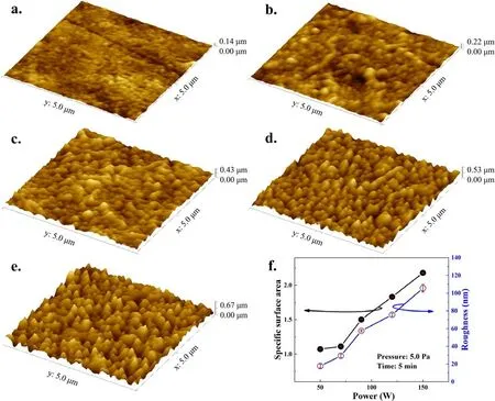
Figure 5.AFM images of samples treated by Ar plasma with gas pressure of 5.0 Pa and input powers of: (a)50 W,(b)70 W,(c)90 W,(d)120 W, (e) 150 W.(f) Power dependence of specific surface area and roughness of samples.
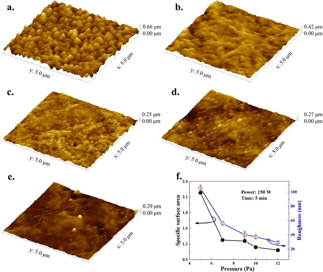
Figure 6.AFM images of samples treated by Ar plasma with input power of 150 W and gas pressures of(a)5.0 Pa,(b)7.0 Pa,(c)9.0 Pa,(d)10.0 Pa, (e) 12.0 Pa.(f) Pressure dependence of specific surface area and roughness of samples.
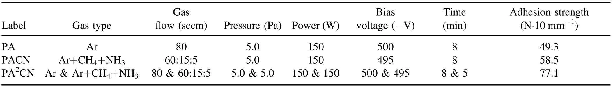
Table 1.Surface adhesion strength of PTFE treated by plasmas with different discharge gases.
3.3.Comparison of single-step method and two-step in-situ method
The adhesion of the PTFE surface not only depends on the mechanical interlocking between bonding surfaces but also on the molecular bonding ability between the PTFE surface and adhesive [36].Therefore, three typical CCP-treated samples were fabricated for comparison.The three groups of experimental conditions are as follows:
(1) PTFE with single-step treatment in Ar CCP for 8 min,marked as PA.This step confirms that a high roughness and specific surface area of the PTFE surface can improve the mechanical interlocking between bonding surfaces.
(2) PTFE with single-step treatment of Ar+CH4+NH3CCP for 8 min, marked as PACN.This step confirms that a-CNx:H cross-linking film can improve the molecular bonding ability between bonding surfaces.
(3) PTFE with two-step in-situ treatment,firstly treated in Ar CCP for 8 min, then in Ar+CH4+NH3CCP for 5 min,marked as PA2CN.This step confirms the role of the combination of mechanical interlocking and molecular bonding between surfaces.
The detailed experimental parameters and results are shown in table 1.The adhesion strength of PA, which represents the mechanical interlocking effect, is 49.3 N·10 mm?1, which is much better than that of the raw sample (20 N·10 mm?1).Meanwhile, the adhesion strength of PACN, which represents molecular bonding ability,is 58.5 N·10 mm?1.It is worth noting that the PA2CN sample shows obvious improvement in adhesion strength (77.1 N·10 mm?1), which is 56% higher than PA and 32% higher than PACN.
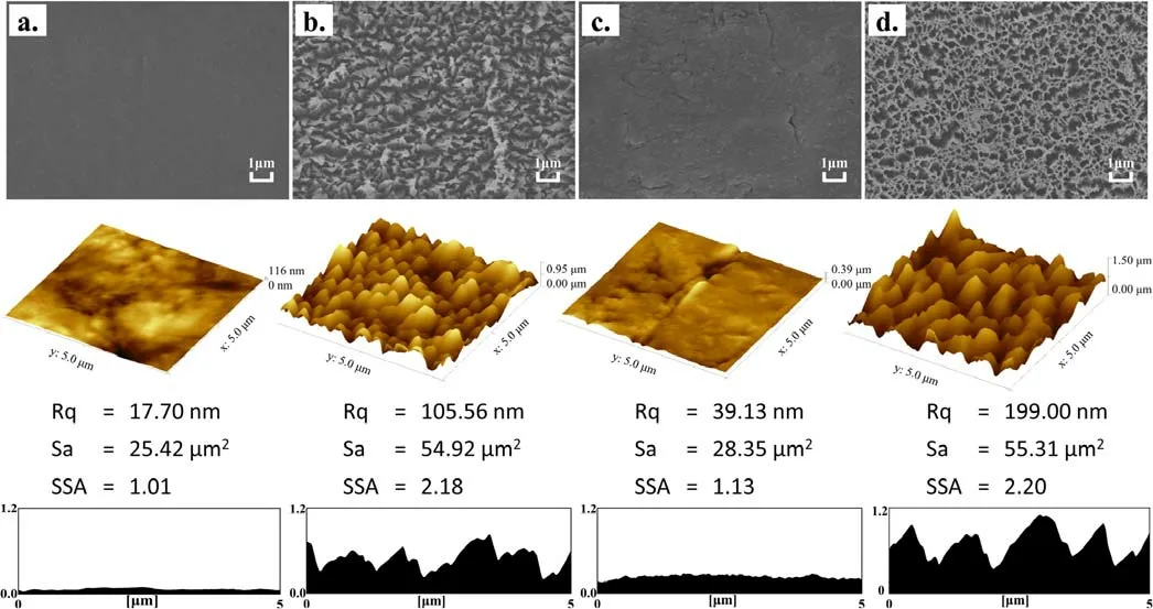
Figure 7.SEM and AFM images of PTFE treated with single-step plasma and two-step in-situ plasma methods: (a) untreated, (b) PA, (c)PACN, (d) PA2CN.
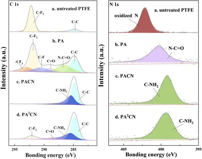
Figure 8.High-resolution C 1 s and N 1 s XPS spectra of untreated PTFE and samples treated by plasma with single-step or two-step in-situ methods.
Figure 7 shows SEM and AFM images of the three samples and the untreated sample.As can be seen,the surface of the untreated sample is extremely smooth, while those of PA and PA2CN with Ar plasma treatment present a textured microstructure with specific surface area greater than 2.0.However, for PACN, although ion bombardment also exists with a bias voltage of about ?500 V, seen from the DC voltmeter, the electronegative plasma takes on a deposition nature.The ion bombardment only strengthens the film deposition, but the role of ion bombardment in the formation of its surface microstructure is limited,which is different from the Ar electropositive plasma.As a result, the surface morphology of the a-CNx:H cross-linking layer grown in the deposited plasma is significantly different from that of the other two.
XPS was used to investigate the chemical state and element content of untreated and plasma-treated PTFE.Compared with the raw PTFE sample, whose F/C ratio is about 2.0,the F/C ratio of PA is significantly reduced to 1.24 due to the argon ion bombardment.Due to the coverage of the a-CNx:H cross-linking film, the F/C ratio of PACN is only about 0.002,while that of PA2CN is 0.32.The XPS spectra of C 1 s and N 1 s are shown in figure 8.The C 1s-XPS spectra of the untreated sample are fitted into two peaks.The peaks located at 284.8 eV and 292.0 eV are assigned to C-C and CF2, respectively.After Ar plasma treatment, CF3,CF,C=O and N-C=O bonds appear on the PA surface because many unsaturated bonds caused by ion bombardment react with O2,N2and water in the air[15,37,38].For the C 1s-XPS spectra of PACN,the CF2peak almost disappears and is replaced by C-C and C-NH2bonds [39].The chemical structure of PA2CN is similar to that of PACN.
The intermolecular force on the surface of the material is proportional to the surface free energy[16,20],and the higher surface free energy indicates better adhesion properties.In order to characterize the surface free energy of the samples with plasma treatment, the contact angles of deionized water and diiodomethane on the PTFE samples were measured to calculate the surface free energy.The formula for the calculation is as follows [40]:
where the subscripts L and S denote liquid and solid surfaces,respectively.The superscripts d and h represent the energies of the dispersion force and the hydrogen bonding force components, respectively.θ is the measured contact angle.The surface free energy of PTFE is the sum ofγSdandγ.Sh
Figure 9 shows the surface free energy of samples treated by the single-step and two-step in-situ methods.The surface free energy of PA is less than that of the untreated sample(21.0 mN m?1).After aging six days, the surface free energy decreases by nearly 35%, and the surface of PA shows superhydrophobic property because of the surface microstructure and molecular chain migration [32, 41-44].The surface free energy of both PACN and PA2CN increases significantly.The surface free energy of PACN is almost 2.5 times that of the original sample, and that of PA2CN reaches 74.0 mN m?1,which is mainly attributed to the combination of both the microstructure of the PA2CN surface and the a-CNx:H film.After aging six days,the surface free energy of PACN is about 50 mN m?1, while that of PA2CN decreases to a certain extent but is still higher than that of PACN.
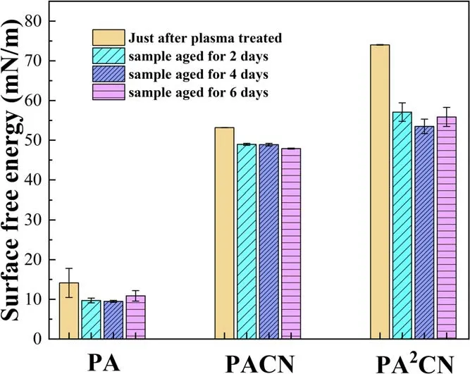
Figure 9.Surface free energy of samples treated by plasma with single-step or two-step in-situ methods.
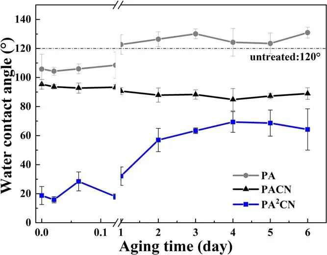
Figure 10.Aging time dependence of water contact angles for samples treated by plasma with single-step or two-step in-situ methods.
Figure 10 shows the changes in the water contact angle of the three samples with aging time.According to Wenzel’s equation [41, 45],
where r, θrand θsare the surface roughness ratio, contact angle of the rough surface and contact angle of the smooth surface, respectively.
When the roughness of a surface increases, hydrophobic substances will be more hydrophobic, and hydrophilic substances will be more hydrophilic[46].That is why the surface of PA with high roughness showed hydrophobic characteristics.The decrease in the water contact angle of PACN is due to the existence of the cross-linking layer on its surface.The water contact angle of the sample treated by two-step in-situ plasma remains low at the initial stage, but with the increase in aging time, the angle rises to 60° and tends to be stable.
4.Conclusions
Ar/Ar+CH4+NH3CCPs were used to treat PTFE.The treatment of Ar CCP caused a hill-shaped microstructure on the PTFE surface with a specific surface area of up to 2.18,while the treatment of Ar+CH4+NH3plasma formed an a-CNx:H cross-linking layer on the surface.After the two-step in-situ plasma treatment, a surface with high specific surface area and extremely low F/C ratio was obtained.XPS analysis showed that the F/C ratio of the surface after the two-step insitu treatment decreased to 0.32, and that polar groups were connected on the surface, improving the molecular bonding ability.In our work, an adhesion strength of PTFE of up to 77.1 N·10 mm?1was achieved after the two-step in-situ plasma treatment, which was 56% higher than PA and 32%higher than PACN.Our results provide a reliable experimental direction for the application of PTFE in the industry.
 Plasma Science and Technology2023年10期
- Plasma Science and Technology的其它文章
- 3D fluid model analysis on the generation of negative hydrogen ions for negative ion source of NBI
- Etching characteristics and surface modification of InGaSnO thin films under Cl2/Ar plasma
- Pulsed gas-liquid discharge plasma catalytic degradation of bisphenol A over graphene/CdS: process parameters optimization and O3 activation mechanism analysis
- A homogeneous atmospheric pressure air plasma in a 10mm gap based on a threeelectrode configuration
- Effect of gas flow on the nanoparticles transport in dusty acetylene plasmas
- Closed corner divertor with B × ?B away from the divertor: a promising divertor scenario for tokamak power exhaust