Redundancy Technologies for Mobile Communication Networks
2008-06-20 08:26:10LiuJingxiangDingYanjingLiuFeng
ZTE Communications 2008年3期
Liu Jingxiang,Ding Yanjing,Liu Feng
(ZTE Corporation, Shenzhen 518057, China)
Abstract:With the growing popularization of mobile communication services,a growing demand for better Quality of Service(QoS)arises from the subscribers.An uninterrupted service provided with the network after a node failure is also expected from operators.To achieve these,duplex backup and even multiple backup functions have been gradually introduced into the network.Among redundancy technologies,dual home and IuFlex are more successful.Dual home is a typical duplex backup system with activation of the standby server after the host server failure.IuFlex is one of the multiple backup technologies with overhead transference to other node in switching pool after single switching node failure.
N etwork security is one of the key factors for guaranteeing good quality of mobile communication services.However,faults of communication network nodes are unavoidable.Since switching equipment plays an important role in mobile communication networks,its malfunctions may bring great loss.Besides,the recovery of such malfunctions always takes a long time.In order to improve network security,vendors have released various redundancy technologies,among which dual home and IuFlex are two mature technologies.The present paper will analyze and compare the two redundancy technologies.
1 Dual-Home Technology
Dual-home technology offers a standby node to one or more working nodes in a communication network.The working nodes,termed as active nodes,are switching equipments used for everyday network operation,while the standby node provides backup for it.The standby node will take the place of the active node to offer services once it detects faults of the active node.The networking models of dual-home system include 1+1 active standby,1+1 mutual standby,N+1 active standby,and N+1 mutual standby.
1.1 Networking Models
(1)1+1 Active Standby
In the 1+1 active standby architecture shown in Figure 1,Server1is the active node,and Server2is the standby node.Server1and Server2have the same capacity and configuration.Mc,the media control interface[1],is used between the servers and Media Gateway(MG).In normal working situations,MG1registers at Server1,and Server1,as the active node,offer services to the network.Once Server1shuts down,Server2is activated,and MG1then changes its registration to Server2;after that,Server2,swapping Server1,begins to offer the services.
(2)1+1 Mutualstandby
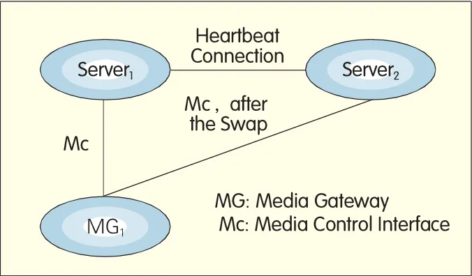
▲Figure 1. 1+1 Active standby dual-home architecture.
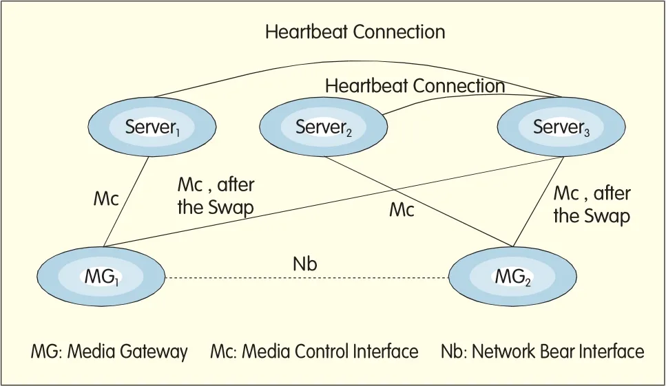
In the 1+1 mutual standby architecture shown in Figure 2,both Server1and Server2have their own services to process;MG1and MG2register at Server1,while MG3registers at Server2.The interface between MGs is Nb.In normal working situations,Server1and Server2just handle their own services.However,when one of them fails to work,the other will take over the services of the malfunctioned one.For example,if Server2has troubles,Server1will swap Server2,and the registration of MG3will be transferred to Server1.

?Figure 2.1+1 mutual standby dual-home architecture.
?Figure 3.N +1 active standby dual-home architecture.
(3)N+1 Active standby
There are N active nodes and one standby node in this architecture.The standby offers redundancy to all the active nodes.Normally,the active nodes are in operation state.If one of the active nodes shuts down,the standby node will be activated to take its services over.
The N+1 active standby architecture is illustrated in Figure 3,in which N=2,Server1and Server2are active nodes,and Server3is the standby.MG1registers at Server1,while MG2at Server2.
(4)N+1 Mutual standby
The difference of the N+1 mutual standby model from the N+1 active standby is that the standby node in this architecture not only backs up active nodes,but also has its own services to handle.
This model is illustrated in Figure 4,in which N=2,Server1and Server2are active nodes,and Server3is the standby.MG1registers at Server1,while MG2at Server2.Server3needs to processes its own services,and MG3registers at it.The services handled by Server3have no standby from other network elements.
1.2 Working Process(1)Fault Detection
(SCTP)to bear heartbeat signals between active and standby servers.In this case,both the servers need an IP address respectively,and IPports for UDP/TCP/SCTPof the heartbeat connection as well.
After the heartbeat connection is built up,the active and standby nodes will keep sending heartbeat messages to each other,and wait for responses.If there is no response,it is regarded as a fault.When the number of faults reaches a threshold value,the active node is regarded as out of service.
The fault detection process also has MG registration decision mechanism to prevent false standby activation caused by temporary errors of the heartbeat connection.If heartbeat is broken,the standby node will detect if MG at the active node communicate with it for re-registration.When the number of MGs re-registered at the standby node surpasses a threshold value,the active node is regarded as out of service,and the standby node is activated to take its services over.
(2)Re-Registration of MG
MG,according to H.248 Protocol,is able to register at more than one server in preference,and the active server has a higher priority.Once the active node works,MG sends a ServiceChange request to it for registration.Upon receiving a successful registration order,MG completes the registration process,and then the active server is configured as the MG control server[2].
Once the active server fails to work,the signaling link between it and the MG is broken.Accordingly,the MG regards the active server as unusable,and then triggers its re-registration process at the standby server.
(3)Signaling Standby
As for the Message Transfer Part
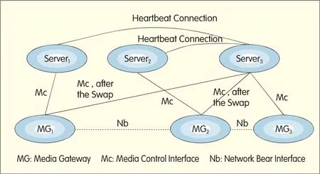
Figure 4.?N +1 mutual standby dual-home architecture.
A heartbeat connection between a standby node and an active node is necessary for achieving the goal that the standby can detect any faults of the active.The heartbeat connection can be based on either IPor Time Division Multiplexing(TDM),however,the IP-based heartbeat is recommended for its easy networking.
The IP-based heartbeat connection may use User Datagram Protocol(UDP),Transmission Control Protocol(TCP)or Stream Control Transmission Protocol(MTP)and IP,two mainstream signaling bearers in existing mobile communications networks,there are different backup solutions to them.
There are two backup schemes for MTP-based signaling protocols,including the Mobile Application Part(MAP),CAMEL Application Part(CAP),ISDN User Part(ISUP),Telephone User Part(TUP)and A interface[3].
·Redundancy Backup of Signaling Link
There is a common Signaling Point(SP)in the active and standby configurations.Adjacent offices treat the active and standby servers as in the same office direction,and deploy MTP links to both the active and the standby.
These MTPlinks have different Signaling Link Codes(SLCs):O-7 for the active node;and 8-15 for the standby node.
In normal operation,the links to the active node are activated,while those to the standby node closed.Therefore,MTP Level 3(MTP3)employs the links to the active node to transfer signaling.Once the active server has troubles,the links to the active node will be halted,while the standby server will activate its links.In this situation,MTP3 uses the links to the standby node for signaling transport.
·Route Redundancy
The active server is deployed with SP A,while the standby server with SPs A and B.Adjacent offices regard the active and standby servers as in two office directions with SPA and SPB respectively.The active server has two signaling routes:the direct active route to A,and the backup route to A via B.
In normal operation,MTP3 employs the active route to transfer signaling.If the active node fails to work,MTP3 will change to use the backup route.After receiving the MTP3 signaling with the destination point code A,the standby server will swap the active server to make a local processing.
The MTP3 User Adaptation Layer(M3UA)is used for IPbearing.There is the common SPA in the active and standby server configurations[4].Adjacent network elements may deploy SPAas an Application Server(AS).The AShas two sets of associations to the active and standby servers respectively.The two sets have the identical association number and bandwidth configuration.Normally,the associations to the active server are activated,while those to the standby are inactive;the signaling to the ASis transported to the active server.Once the active server has faults,the associations to the standby are activated,and the signaling to the ASis then transferred to the standby server.
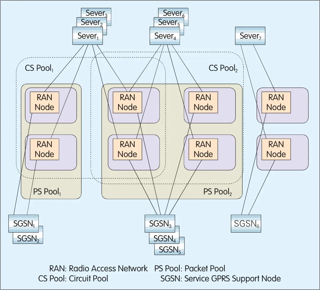
Figure 5.?Typicalpool architecture.
(4)Service Redundancy
The standby server should have the same service characteristics with the active server,because the former will swap the latter to provide services.To fulfill this,the synchronization between service configuration data at the active and standby servers should be supported.Any changes of service configuration data at the Operation and Maintenance(O&M)platform of the active server will be synchronized to the standby server through IPconnection between the two O&M platforms.
2 IuFlex Technology
IuFlex,introduced in 3GPPR5,enables the intra-domain connection route from a Radio Access Network(RAN)node to multiple Core Network(CN)nodes.After a user initiates a service,the RAN node routes the initiation message to a suitable CNnode for service processing.The RAN and CN nodes form a switch pool.
2.1 Networking Model
Figure 5[5]shows a typical pool architecture.As a simple illustration,the figure does not mark up the MGs in CN.
2.2 Service Process
(1)Non Access Stratum(NAS)Node Selection Function(NNSF)
The NNSFenables the RAN node to select the CN nodes by the International Mobile Subscriber Identity(IMSI)or Temporary Mobile Subscriber Identity(TMSI).It can make a user in the pool keep the access to the same CN node throughout,avoiding unnecessary location update caused by variation of user's location in pool.
The mapping relationship between IMSIand CN nodes is not fixed.The RAN node may change the mapping according to time and load.
(2)Network Resource Identifier(NRI)
An NRIexclusively identifies a CN node in the pool.One NRIcannot be reused in the pool and other intersected pools.However,a CNnode is allowed to have multiple NRIs[6].
TMSIcarries the NRImessage between CNand RAN nodes.The NRI message length is O-1Obits,located at from bit 14 to bit 23 of the 32-bit TMSI[7].
NRIhas its mask,which includes NRI's bit length and its start bit in TMSI.NRIcan be deduced from the TMSIand NRImask.The NRImask is exclusive in the switch pool.
In the pool,Null NRIis special.It is used for migration procedure of users in the pool,and does not belong to any CN nodes.
(3)Location Update
If a user in the pool uses IMSIto initiate a location update request,the RAN node will use NNSFto define the corresponding NRIvia IMSI,and routing signaling to the server that the NRI corresponds to.The server receives and handles the request.After the location is updated,the server will initiate a TMSI reallocation procedure.The reallocated TMSIincludes the NRImessage of the server,and is responsible for initiating the user's subsequent services.The RAN makes sure that the subsequent services are routed to the same server for processing[8].
If a user in the pooluses TMSIto initiate a location update request,the RAN node will deduce the NRIfrom the TMSIand NRImask,and,according to the NRI,get to know the server where the user has registered.The server makes location update after the request is routed to it.
(4)Calling Procedure
If a user in the pool employs IMSIto initiate a calling request,the RAN node uses NNSFto obtain NRIcorresponding to the IMSI,and then routes signaling to the server corresponding to the NRI.The server handles the request,and initiates a TMSIreallocation procedure.The reallocated TMSIincludes the NRI message of the server,and is responsible for initiating the user's subsequent services.
If a user in the pool uses TMSIto initiate a calling request,the RANnode will deduce the NRIfrom the TMSIand NRImask,and,according to the NRI,fix the server where the user has registered.
The server makes calling processing after the request is routed to it.
(5)Call Responding Procedure
The calling request includes the Global-CN-IDof the called party.If the request has IMSI,the RAN willstore the relationship of the IMSIand Global-CN-ID temporarily.Once the called party uses its IMSIto respond,the RAN will use the Global-CN-ID to find the server that is responsible for handling the request respond,and send the response to it.
If the request has TMSI,the RAN will identify the connected Mobile Switching Center(MSC)according to the NRIin the TMSI[9].
(6)Redundancy Processing
If one server in the poolfails to work,the RAN will identify it,and transfer the service requests allocated to it to other available servers.In this way,the redundancy of servers in the pool is fulfilled.
The new server will handle location update requests initiated by the registered users at the malfunction server,and initiate a TMSIreallocation procedure.The reallocated TMSI includes the NRImessage of the new server,and is responsible for the initiation of users'subsequent services.
If a registered user at the malfunction server initiates a calling,the RAN will distribute the request to an available server in the pool.However,as the TMSI in the request is not allocated by the home office of the available server,the server will refuse the calling with an excuse of unknown user.Then the user will use IMSIto initiate a location update request,and re-register at the new server through the NNSF.
(7)User Migration
User migration is another redundancy solution to IuFlex network.Before a server is maintained,its users are migrated to other normally working servers,and the load remains balanced at the same time;after the maintenance is completed,the users are migrated back to the server.
Triggered by the O&M order,user migration is implemented through the following steps:
·The O&M order configures the maintained server status at the RAN node and other servers in the pool.The status is set as being uninstalled.
·The server in the uninstalled status handles services initiated by its registered users,and reallocates a TMSI with Null NRIto the user terminal.The TMSIalso carries non-broadcast Local Area Identification(LAI)at the home office.
·Once the user terminal closes the current service,it will immediately use previously allocated TMSIto initiate a location update request,because the non-broadcast LAIis different from the LAIbroadcast by the RAN.
·Thanks to Null NRIin the TMSI,the RAN,after receiving the location update request,will select a new server according to the capacity of available servers in the pool,and then send the request to the selected server for location update processing and TMSI reallocation.The reallocated TMSIhas NRIof the home office.During the location update,the new server deduces the user's home server from the non-broadcast LAI,and acquires the user's IMSIand authorization encryption data from its home server.
It usually takes 2-3 location update periods to complete migration of all the users of a server.Besides,user migration can be conducted on partial users of a server,so as to fulfill load adjustment among the servers in the pool.
Different from ordinary redundancy,user migration is triggered by the O&M order,and requires the uninstalled server to participate in the migration process.Therefore,user migration is inapplicable to the redundancy of node down caused by a sudden disaster.
3 Comparisons of Dual Home and IuFlex
The dual-home technology can fulfill redundancy of server nodes with no need of coordination of external network elements.Therefore,it is applicable to large trans-regional local networks.Operators can select proper dual-home schemes for new switching offices according to their local networking plans.The IuFlex technology involves the access network.Iu interfaces of RNC are physically connected to multiple MGs in the pool simultaneously.Therefore,IuFlex brings a relatively high cost for network improvement.However,as a redundancy technology,IuFlex also has the capability of load sharing and management,and enables the decrease of signaling traffic in network.Accordingly,the technology is recommended for big cities with dense population and multiple switching offices.
ZTE's switching office project in Shandong is taken as an example here.In the project,new switching offices are required to be built in seven regions in Shandong,China with subscribers of from 1OOthousand to 2OOthousand.In order to improve O&M efficiency,every region is deployed with a MG,and two Mobile Switching Center Servers(MSCSs)are deployed in Jinan and Qingdao separately for the MG management.Figure 6 shows the networking model of the project.As both servers have the capacity of more than 5OOthousand subscribers,any server node faults may lead to large-scale network paralysis.According to the features of this networking model,1+1 mutual standby dual-home redundancy is adopted.If one of the servers in Jinan or Qingdao fails to work,the other server may detect the faults via the heartbeat connection between them,and allows the re-registration of the MGs.Then it swaps the failed server to offer network services.Such dual-home networking not only improves the network security,but also facilitates system maintenance processes such as software/hardware upgrade,and reduces service interruptions caused by server maintenance.
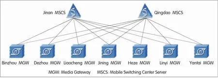
▲Figure 6. ZTE's dual-home networking model in Shandong.
4 ZTE's WCN Switch
As the kernel of ZTE's mobile communication products,its Wireless Core Network(WCN)switch fully supports both dual-home and IuFlex redundancy.It has successfully been applied in large-scale networks.
In dual-home networking,WCN,when used as a standby node,can provide 16 master nodes with redundancy backup.It supports fault detection in less than 6Os,and service recovery in less than 12Os.
In IuFlex networking,WCN can support 16 switches at most in the pool to share load.
5 Conclusion
With different technological implementation,both dual home and IuFlex redundancy can solve switching node faults in mobile communication networks,improving network reliability and Quality of Service(QoS).Therefore,they are getting increasing attention from the operators worldwide.

- ZTE Communications的其它文章
- WiMAX and Its Applications (3)
- An Access Selection Functional Architecturefor Heterogeneous Multi-Mode Terminals
- Ultra Mobile Broadband Technology Overview and Competitive Advantages
- Ambient Network and Its Key Technologies
- Key Technologies of Wireless Heterogeneous Network Security
- Multi-Radio Cooperation Technology and Heterogeneous Network Convergence