Analysis on Velocity Characteristics of Cavitation Flow Around Hydrofoil
2010-07-25 06:21:44LIXiangbin李向賓LIUShuyan劉淑艷WANGGuoyu王國玉ZHANGBo張博ZHANGMindi張敏弟
Defence Technology 2010年3期
LI Xiang-bin(李向賓),LIU Shu-yan(劉淑艷),WANG Guo-yu(王國玉),ZHANG Bo(張博),ZHANG Min-di(張敏弟)
(1.School of Nuclear Science& Engineering,North China Electric Power University,Beijing 102206,China;2.School of Mechanical and Vehicular Engineering,Beijing Institute of Technology,Beijing 100081,China)
Introduction
As a complicated flowing phenomenon,the cavitation involves unsteadiness, multiphase flows, compressing,mass transfer and exchange between vapor and liquid phases[1].So far,these interactions have not been well understood,and the experimental research is the most effective method to reveal these interior laws.Through the experimental observations,under a given Reynolds number and attack angle,the cavitation around a hydrofoil can be divided into four stages,such as incipient cavitation,sheet cavitation,cloud cavitation and supercavitation,according to the cavitation's different morphological characteristics appearing in the change of the cavitation number[2-3].
With the development of flow visualization technique,many methods have been used to study the relations between the flow structures and cavitation.Arakeri and Acosta[4]observed the cavitation in the flow around two axially symmetric bodies with hologram photography method.Katz investigated the effect of the axial shear vortex on the cavitation in the separated region[5].Franc and Michel observed the attached cavitation around different head-type hydrofoils by using sodium fluorescein as colouring agent[6].Since 1990s,with the improvement of the experimental techniques and relative instruments,the high speed camera,laser Doppler velocimeter(LDV),micro-transducers and computer-image processing have been used to investigate the cavitation evolvement in high-speed flow fields,capture its mechanism and interaction with turbulence flows.Kubota observed the influence of the reentrant jet on the unsteady trailing edge of cavitation area[7].WANG,et al researched the static and dynamic characteristics of the attached cavitation around the hydrofoil,and measured the velocity distribution and lift-drag coefficients with LDV[8].The particle image velocimeter(PIV)has been used to measure the cavitation flows as its advantage of non-interfering,transient and full-flow-fields quantitative measurement[9].By using solid tracing particles,Tassin et al discussed the feasibility of investigating cavitation flow with PIV[10].Foeth observed the flow structures of sheet and cloud cavitations[11].Lately,using bubble as tracing particle,Wosnik and Milosevic observed the ventilated supercavitation in turbulent bubbly wakes[12].WANG,et al investigated the multiphase flow dynamics in the supercavitation regime with PIV and high speed photograph[13].
This paper focuses on the hydronautics supercavitation hydrofoil.The digital particle image velocimetry(DPIV)technique is used to observe the velocity characteristics near the hydrofoil.In the DPIV measurements,both the vapor resulted from cavitation and the air bubbles entrained from the inlet are used as the tracer particles to capture the relative information.
1 Experimental Setup
1.1 Cavitation Tunnel
The experiments are carried out in a closed cavitation tunnel,as shown in Fig.1.An axial-flow pump is located about 5 m below the test section to separate it from the cavitation near the pump.A tank of 5 m3in volume is placed in the upstream of the test section to eliminate the undesired free bubbles in the water stream.The top of the tank is connected to a vacuum pump to control the pressure in the tunnel.Between the test section and the tank's outlet,a square guide grid and a straight-line guide grid are used to reduce the turbulence level.The cycle flow is driven by the axial pump.
The position of the hydrofoil located in the rectangular test section of 2cin width is given in Fig.2,wherecstands for the chord length of the hydrofoil.And,the flow phenomena are observed through three windows located on top,bottom and side respectively,which are made of transparent perspex.
The cavitation numberσand Reynolds numberReare defined as
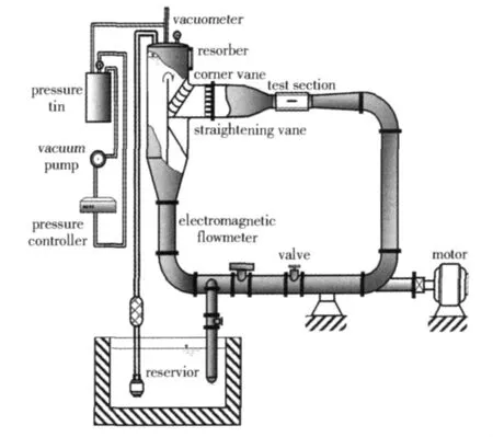
Fig.1 Sketch of cavitation tunnel
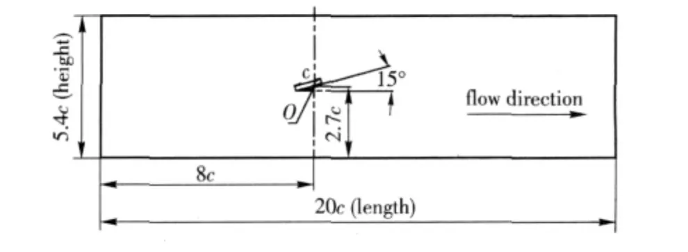
Fig.2 Hydrofoil in test section

whereP∞andUare the reference static pressure,the reference velocity,measured at 210 mm upstream from the hydrofoil mid-chord,Pvthe vapor pressure,ρthe water density,cthe chord length of the hydrofoil,νthe kinematic viscosity of the water.In this experiment,Reynolds number is always 3.5 ×10⁵.
1.2 Supercavitation Hydrofoil
The special hydronautics hydrofoil proposed by Tulin[14],as shown in Fig.3,is adopted in the experiment.It is made of stainless steel,highly polished and clamped on the wall of the test section with a mechanical mounting device,which enables the hydrofoil to be adjusted to a given attack angle.Its suction surface is located in the bottom to view the flowing field easily.The definition of attack angle is also presented in Fig.3.
1.3 DPIV System

Fig.3 Sketch of hydronautics supercavitation hydrofoil
As shown in Fig.4,a 2D-PIV system made by TSI,consists of a double-pulsed Nd:YAG laser emitting sheet laser,a PIVCAM 10-30 CCD camera with resolution of 12 bits,1 024 ×1 024 pixels collecting the instantaneous images,and a synchronizer providing the timing and sequencing of events.The precision of the whole system is within 0.5% ~2%.In the experiment,the pulse laser sheet is output from a light-guide arm located in the bottom of the test section,and illuminates the dydrofoil's mid-section.The captured images are transferred to a computer.

Fig.4 Layout of experimental setup
In the cavitating flow,the free stream carries some air bubbles and the numerous vapor bubbles exist in the cavitating region also.The velocity information inside the cavity can also be obtained by using the vapor bubbles as tracer particles,as mentioned by Wosnik & Milosevic[12].In the experiment,the commercial PIV-software Insight from TSI is used to process the velocity vector fields with an interpretation area of 32 × 32 pixels and 50% overlap in general.The cross-correlation of two image frames are calculated by using fast Fourier transforms(FFT),the peak search is realized with Gaussian algorithm,and the multiple filters are also employed to remove the noise and interference.
2 Results and Discussions
2.1 Flow Structures
In the experiment,the different flow patterns appear in response to the variation of the cavitation numbers by changing the upstream pressure from the test section with constant flow velocity.The typical patterns are captured by high speed camera for convenient comparison,as shown in Fig.5.

Fig.5 Flow structures in different cavitation stages
When the cavitation number is 2.07,the strip or sheet cavitation appears on the hydrofoil suction surface,similar to the attached sheet cavitation.If the cavitation number decreases to 1.15,the shedding of cloud cavitation has formed behind the hydrofoil.And if the cavitation number lowers to 0.44,the hydrofoil's suction surface is covered by cavitation completely,and the supercavitation forms while the cavitation boundary extends backwards,although there is strong fluctuation near the cavitation trail.
2.2 Velocity Distribution
The full flow field is measured by 2D-PIV system,and its time-averaged velocity vector and contour plots are obtained by using post-processing software,as shown in Fig.6 and Fig.7.In the figures,the gray areas indicate no laser light entered since the sheet light comes from the section's bottom.In the sheet cavitation stage,when the cavitation numberσ= 2.07,the whole flow field can be divided into two areas.In the rear portion of the hydrofoil suction surface,the velocity is much lower than that in the main flow region,with high velocity gradient,and extends backwards to form a wake,thus,this area is characterized as low velocity and high fluctuation area.In the other region,no large velocity fluctuation occurs.This area is characterized as main stream(free stream)area.

Fig.6 Velocity vector plots under different cavitation numbers
As shown in Fig.7,with decrease of the cavitation number,the difference in velocity distributions appears.
Firstly,the high-fluctuation region with lower velocity corresponds to the cavitation area,and varies with the cavitation structures.For the flow structures shown in Fig.5,there is little velocity fluctuation in the smaller area of attached sheet cavitation.In the cloud cavitation stage,the shedding and collapse of the cavitation cloud near cavitation trail results in large fluctuation of flow velocity,revealing obvious corresponding relation.

Fig.7 Velocity contour plots under different cavitation numbers
Secondly,with the cavitation number decreases,the lower-velocity distribution area varies continuously,and becomes smaller and moves to downstream.When the cavitation numberσ=2.07,the lower-velocity distribution area,v< 2.5 m/s,extends only along the shearing flow from the separation points ofthe hydrofoil's leading and trail parts.Meanwhile,the higher velocity area still covers the hydrofoil suction surface.When the cavitation numberσ=1.15 andσ=0.44,a relatively stable cavitation area covers the entire hydrofoil suction surface,the lowest velocity area,namely the cavity core,is closely adjacent to the rear of the suction surface.With the decrease of cavitation number,the lowest velocity area moves to downstream and becomes smaller,and the velocity gradient with monotone increasing from inside to outside occurs.
Thirdly,the main-stream velocity distribution in the rear of the hydrofoil varies from even to fluctuant and even again with the decrease of cavitation number.When the cavitation numberσ=2.07, the main stream flows evenly,various velocity areas behave as stratified a distribution along the streamline.When the cavitation number decreases to 1.15,the shedding and collapse of the vortices near cavitation trail result in a large fluctuation of flow velocity,and various velocity gradient distributions appear in the main stream area,which reveals that the flow field is affected violently by the cloud cavitation.When the cavitation numberσ=0.04,the main-stream velocity under the hydrofoil becomes smoothly again.
Finally,in the supercavitation stage,the velocity distribution in the cavitation region corresponding to the front of the hydrofoil's suction surface is similar to that of the main stream,while the other cavitation areas are still lower velocity areas.In various stages before supercavitation,the front of hydrofoil suction surface is lower-velocity area.While in the supercavitation stage,the cavitation area near the leading part of the hydrofoil suction surface is in pure vapor phase,although its rear part is still in the water-vapor mixture phase.Clearly,the difference in the water-vapor distributions results in different velocity distributions[15],and it is a distinct feature in the supercavitation stage.
In order to offer more visual velocity distribution structures,a group of special sections are selected,as shown in Fig.8.Starting from the section at the hydrofoil's leading point,the horizontal distances of the selected sections are 0.5c,1.1c,0.7c and 2.3c respectively.The corresponding velocity distributions under various cavitation numbers are shown in Fig.9.It can be found that the lowest velocity distribution varies with the development of cavitation.In the positions ofx=0.5c andx=1.1c,the lowest velocity distribution curves in the cavity core vary from the initial double-trough shape to smooth single-trough one,and becomes smaller.In the position ofx=2.3c,the lowest velocity is smaller than that in other stages,and it indicates that the lower velocity area moves to downstream.

Fig.8 Sketch of special locations
3 Conclusions
The cavitation flow around the supercavitation hydrofoil can be observed by means of DPIV method.In the PIV measurements,the bubbles entrained by the flow can be used as the tracer particles.The following points can be concluded.
1)The velocity distribution in the whole flow field depends on the development of cavitation areas.The high-fluctuation region with lower velocity corresponds to the cavitation area,and varies with the cavitation structures.
2)With the decrease of cavitation number,the lowest velocity distribution in the cavity core becomes more even,from initial double-trough shape to smooth single-trough one,and its influence becomes smaller as moving to the downstream.
3)The main-stream's velocity distribution behind the hydrofoil is from even to fluctuant and even again with the decrease of cavitation number.In the supercavitation stage,the velocity distribution in the cavitation region,corresponding to the front of the hydrofoil's suction surface,is similar to that in the main stream,while the velocity distribution in other cavitation area is still lower.

Fig.9 Time-averaged velocity distributions in different sections
[1]Andrew J S,Brian D S,Antony P,et al.Heat and masstransfer during the violent collapse of nonspherical bubbles[J].Physics of Fluids,2003,15(9):2576 -2586.
[2]Knapp R T,Daily J W,Hammitt F G.Cavitation[M].New York:McGraw-Hill,1970.
[3]Brennen C E.Cavitation and bubble dynamics[M].UK:Oxford University Press,1995.
[4]Arakeri V H,Acosta A J.Viscous effects in the inception of cavitation on axisymmetric bodies[J].Journal of Fluids Engineering,1973,95(4):519-527.
[5]Katz J.Cavitation phenomena within region of flow separation[J].Journal of Fluid Mechanics,1984,140(4):397-436.
[6]Franc J P,Michel J M.Attached cavitation and the boundary layer:experimental investigation and numerical treatment[J].Journal of Fluid Mechanics,1985,154(1):63-90.
[7]Kubota A,Kato H,Yamaguchi H,et al.Unsteady structure measurement of cloud cavitation on a hydrofoil section using conditional sampling technique[J].Journal of Fluids Engineering,1989,111(2):204-210.
[8]Wang G Y,Senocak I,Shyy W,et al.Dynamics of attached turbulent cavitating flows[J].Progress in Aerospace Sciences,2001,37(6):551-581.
[9]Adrian R J.Twenty years of particle image velocimetry[J].Experiments in Fluids,2005,39(2):159 -169.
[10]Tassin A L,Li C Y,Ceccio S L,et al.Velocity field measurements of cavitating flows[J].Experiments in Fluids,1995,20(2):125-130.
[11]Foeth E J,Van Doorne C W H,Van Terwisga T.Time resolved PIV and flow visualization of 3D sheet cavitation[J].Experiments in Fluids,2006,40(4):503 -513.
[12]Wosnik M,Milosevic I.Time-resolved particle image velometry(TR-PIV)in ventilated and naturally cavitating flows[C]∥ The Sixth International Symposium on Particle Image Velocimetry, Pasadena, California,USA,2005.
[13]LI Xiang-bin,WANG Guo-yu,ZHANG Min-di,et al.Structures of supercavitating multiphase flows[J].International Journal of Thermal Sciences,2008,47(10):1263-1275.
[14]Tulin M P.The history and principles of operation of supercavitating propellers[C]∥RTO AVT/VKI Special Course:Supercavitating Flows.Belgium:Von Karman Institute for Fluid Dynamics,2001:1 -25.
[15]LI Xiang-bin,WANG Guo-yu,ZHANG Min-di,et al.Observation of supercavitation aspects around a hydronautics hydrofoil[J].Transactions of Beijing Institute of Technology,2007,27(3):214 -217.(in Chinese)

- Defence Technology的其它文章
- Influence of Accelerated Aging on Detonation Performance of Explosives
- Research on Additional Loss of Guidance Optical Fiber
- An HLA/RTI Architecture Based on Multi-thread Processing
- A Fuzzy Adaptive Algorithm Based on“Current”Statistical Model for Maneuvering Target Tracking
- Quantitative Analysis of Components in OC-CS Sprays by High Performance Liquid Chromatography with Double Wavelength UV Detection
- A New Chaotic Genetic Hybrid Algorithm and Its Applications in Mechanical Optimization Design