直驅式電液傳動系統力的控制研究
2013-08-22 11:23:32萬二平徐正昭
機床與液壓 2013年24期
周 雄,萬二平,徐正昭
1.重慶科技學院,重慶 401331;2.寧波南車新能源科技有限公司,浙江 寧波 315111;3.重慶大學,重慶 400044
1.Introduction
Direct-drive electro-hydraulic drive system is a new hydraulic servo control system developed in recent years,which mostly uses flow servo motor,with fixed displacement pump instead of the traditional servo valve and variable pump,it use ACservo motor drive dosing pumps,dosing pumps drive hydraulic cylinders directly[1-4]. Through the exchange speed of motor itself,commutation,the torque limit function to replace flow control valves,directional control valves,and pressure control valve.Therefore,the direct-drive servo system can change direction of movement and speed of the actuator easily,and greatly reduce the oil losses in the throttling.Compared with conventional hydraulic servo system,it with high energy efficient,compact integrated,easy to operate,etc.Right now,it has been applied in many fields and has achieved great economic benefits[5].
The paper analyze the principles and characteristics of direct-drive electro-hydraulic system establish open direct drive electro-hydraulic drive system,and establish the mathematical model of system platform,build experimental platform and do some experimental analysis.Carry out experimental studies of pressure control of direct drive electro-hydraulic drive system and provide a reference for further work and improvements direction.
2.Principle of electro-hydraulic drive system
The experimental system uses a direct drive open electro-hydraulic drive system,AC servo motor drive one-way screw driven hydraulic cylinders,it can realize frequency control,reverse solenoid valve controlled by the PLC to achieve commutation function.Pressure sensor achieves the pressure feedback control loop[6-7].Displacement sensor achieves displacement closed-loop control.When Piston rod stretch,the oil enter cylinder upper chamber.The oil of lower chamber back to tank.When the piston rod retracted,solenoid valve commutation,the oil enters the lower chamber,the oil of upper chamber back to tank.It realizes the inverter circuit commutation functions.
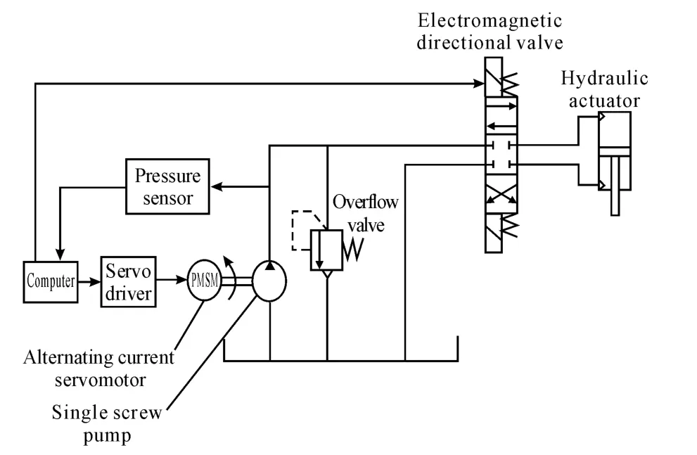
Fig.1 Schematic of energy-efficient hydraulic power system
Figure a direct-drive electro-hydraulic experimental platform for traditional systems operating principle.
3.Composition of experimental system and component
3.1.Composition of experimental system
The item is the Chongqing municipal natural science foundation,applied joint by Chongqing University and Chongqing Technology college,the system is the"electro-hydraulic drive and control”test bed.The experiment is carried out with the screw pump,it uses PLC as the control system,it consists of servo motor,hydraulic cylinders,and a hydraulic loading system[8].The hydraulic loading system can be used to simulate different load conditions of the operation,monitoring and control system can be used to detect the operating parameters.The system operation can be controlled by computer.Fig.2 shows the direct-drive servo-controlled electro-hydraulic transmission experiment system schematic.
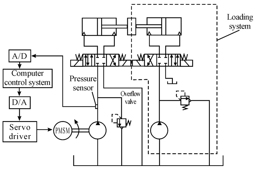
Fig.2 Direct-drive electro-hydraulic drive system(including loading section)
Three-phase power access servo drive input side,through control signal of PLC and servo drive,the 380V/50Hz power supply voltage signal is converted into a sinusoidal step synchronous,motor driven pump through rigid coupling(screw pump)rotates.The test pump output pressure oil,the oil through three ways valve driven a single hydraulic cylinder rod asymmetric doing stretching exercise,hydraulic cylinders telescopic movement rely valve commutation.Relief valve is connected with the open tank,set a certain pressure to prevent system overload according to the conditions of the specific circumstances.The oil with low pressure of Asymmetric hydraulic cylinder outlet port through the value back into the tank.Loading system is similar,mainly by the open tank,general motors,hydraulic pumps,pressure relief valve and a hydraulic cylinder specification as composition.
3.2.System component
The System consists of the following components:
Controller system:SIMATIC S7-200,include RM231 and RM232.Servo motor:Yaskawa SGMGH-13ACA61,Yaskawa servo drive SGMGH-13A.Hydraulic cylinder:Chongqing Hai Chung company hydraulic cylinders,stroke 50 mm,diameter 50 mm,Rod 36 mm.Screw:Italian Saitema continuum high pressure pump,pump displacement 4 cc.Relief:6 L bell set pressure 12 Mp.Sensor:KTC displacement sensors,transmitters Yokogawa EJA430A.Simulated load:Equivalent load 5~10 Mp.Data acquisition system:Yokogawa MW-100 signal acquisition instrument.
4.Electro-hydraulic drive system mathematical model
4.1.Mathematical model of motor speed
Depend on the principles of motor system and basic formulas,derived part of the transfer function block diagram of the motor speed from the literature,shown in Fig.3.The outer ring is the servo motor speed control loop,the PID is internal drive control link.
In order to analyze and experimental convenience,idealization the model to inertia,it still meets the requirements of system analysis:
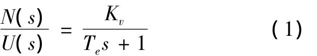
In formula:N(s)is AC servo system output speed(r/s);U(s)is AC servo system input command voltage(V);Teis AC servo system speed gain,set by the driver,adjustable,(r/s/V);Kvis AC servo system electrical time constants(s).

Fig.3 Permanent magnet synchronous servo motor system transfer function block diagram
Optical encoder as a part of the scale factor.
Displacement sensor and pressure sensor transfer function is:
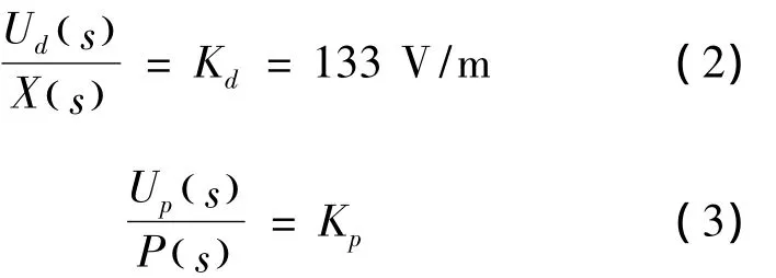
In formula:Ud(s)is displacement sensor voltage(V),Kdis displacement sensor gain(V/rad),Up(s)is pressure sensor voltage(V).Kpis pressure sensor gain(V/MPa).
4.2.Pump control system transfer function
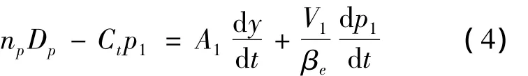
When System works,low pressure chamber working pressure is always 0,ignore the oil return chamber leak,the resulting forward movement of the piston continuity equation:
Reverse movement of the piston continuity equation:

In formula:Ctis total leakage coefficient(including the inner cylinder and the pump discharge and leakage coefficient)(m3/s· Pa),npis pump speed(r/s),Dpis pump displacement(m3/r),A1is hydraulic cylinder rod chamber area(m2),A2is hydraulic cylinder rod chamber area(m2),V1is bit asymmetric cylinder pressure chamber volume(m3),V2is rod chamber when the median volume(m3),βeis bulk modulus of elasticity(Pa),Q2is hydraulic cylinder return oil chamber flows(m3/s),y is piston displacement(m),p1is high-pressure chamber pressure(MPa),p2is low pressure chamber pressure(MPa).
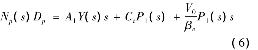
According to the assumption,hydraulic oil flows through the fill valve pressure losses are negligible,the pressure inside the tank as constant Pressure.Consider the pressure of low pressure chamber is constant,linear analysis contains low pressure chamber pressure can be omitted items on formula(6)for pull-type transformation we have:
Hydraulic cylinder and load force balance equation is:
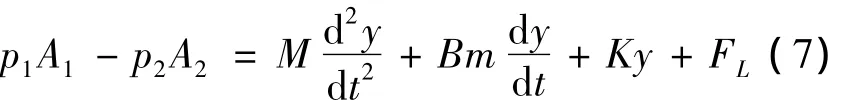
In formula:M is the total load equivalent quality(kg),Bmis viscous drag coefficient N/(m/s),K is load spring stiffness(N/m),FLis load disturbances.
For 3-20 doing the initial value of 0 LAPLACE transform establish the hydraulic cylinder pressure pump control block diagram shown in Fig.4:

Fig.4 Cylinder pump control block diagram of the forward movement
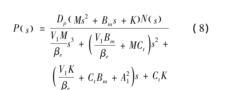
In this experiment,two isolated circuits can be regarded as the gain of the proportional component is 1.Forward movement of the piston rod,in order to facilitate accurate simulation data obtained in this transfer function is no longer on simplification.Pressure control experimental platform mathematical model is:
Reverse movement when the piston rod,since the test system is a reversing valve assume the role of one-way pump—Screw pump,so the forward and reverse motion equation is the same,the entire servo system transfer function is the same,not in this list.
In formula;K'is open-loop gain,K'=KvDp/A2;pump displacement,Dp=4 × 10⁻⁶m3;the cylinder rod chamber area,A1=1.963 ×10⁻³m2;the cylinder rod chamber area,A2=9.46 ×10⁻⁴m2;the total cylinder leakage coefficient,Ct=7.8 × 10⁻¹¹m3/s/Pa;C,effective bulk modulus of elasticity,βe=7 ×10⁸N/m2;Asymmetric Cylinder large cavity volume median and pipes,V1=0.83 × 10⁻³m3;small chamber in the cylinder asymmetric bit volume,V2=0.51 ×10⁻⁴m3;viscous drag coefficient,Bm=500 N/(m/s);the high pressure chamber volume of the total volume,V=1.33 ×10⁻³m3.
5.Computer simulations
Establish direct drive electro-hydraulic drive system simulation model with Simulink.About the pressure control experiments,this system do experiment simulation with step load 1 000 N and 500 N with PID.Fig.5 is 500 N of the PID control response,Fig.6 is 1 000 N of the PID control response,as shown in Fig.5 and Fig.6.

Fig.5 Step force 500 N response

Fig.6 Step force 1 000 N response
Experiments show that PID algorithm simulation graph shows the pressure of direct-drive electro-hydraulic system has a good dynamic response characteristic;it has small overshoot,simulation overshoot of 0.1%or less,PID theoretical simulation pressure response time can be up to 0.1 s,system response is very rapid.
6.Experiments and analyze
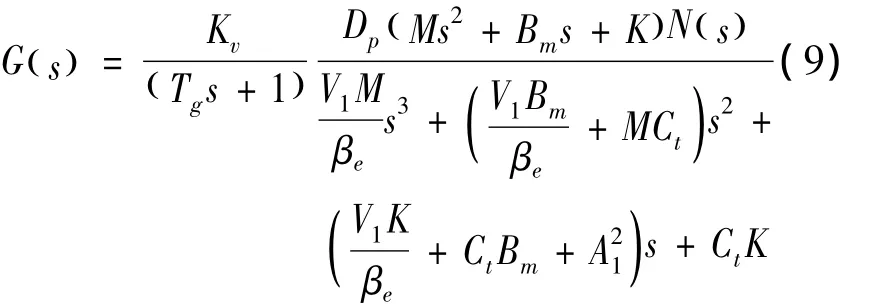
For the direct-drive electric hydraulic drive system,respectively,made of 5 MPa and 10 MPa step load response experiment,as shown in Fig.7 and Fig.8,the abscissa is a time axis,per unit of 10 seconds and the vertical axis is the analog amount of voltage per unit of 1 V,0~5 V voltage range corresponding simulated load 0 ~13 MPa.
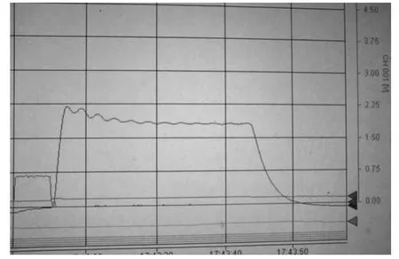
Fig.7 Equivalent load step response 5 MPa
Fig.8 Equivalent load step response 10 MPa
Experimental results show that the step force response is slow,5 MPa(Fig.7)force response time is about 2 s,and overshoot is up to 14%;when load is 10 MPa(Fig.8)overshoot reaches 12%,about 0.6 MPa,it indicates that the pressure control system can track step force signal effectively,but the response is slow,It shakes frequently when it reach steady state,the step response is not ideal.Through access to information and comparative analysis,it is mainly because of the following reasons:
1)In this study,use manual pressure relief valve,pressure relief than the column can be used effectively reduces overshoot,improve response;
2)Hydraulic cylinder stroke is too small.Observed experimentally in the pressure control signal,the maximum stroke hydraulic cylinders rushed directly,and then slowly retreated to the setting pressure,which result the overshoot Serious in Fig.8,and pre-steady state oscillation frequency is inconsistent with frequency of steady state.In this study,the hydraulic cylinder stroke is only 50 mm,the hydraulic cylinder stroke of the current research conducted in this field,generally above 200.
3)As used in this experiment open system,pipeline length up to 1 m,and it’s analog control,the pump is too small,so many factors in this experimental system result the pressure response time is very slow,only about 2 s.
7.Conclusions
The paper Established an open direct drive electro-hydraulic system and platform mathematical model,use Matlab/Simulink software model for the simulation analysis to verify the mathematical model of the platform is accurate,it can accurately describe the system,and analyze the experimental system,experiments show that the open direct-drive electro-hydraulic drive system with screw pump can track step force effectively,but the effect is not ideal.For some open direct drive electro-hydraulic drive system pressure control,it needs further study.
[1] LIU Qinghe.Servo direct drives.Electrohydraulic Compendium of Technical Information,1999:1-3.
[2] JIANG Jihai,TUWanli,CAOJian.Rocket steering volume control with direct-drive servo system[J].Fluid Power Transmission and Control.2005,1.
[3] ZHANG Ding,XU Bing,YANG Huayong,et al.Variable speed pump controlled hydraulic cylinder experimental simulation of hydraulic and pneumatic,2003(1):18-20.
[4] LI Gejiang,LI Weiyi,WANG Hanjie.Direct-drive volume control servo power system studies[J].Machine Tool& Hydraulics,2010(20):44-45.
[5] QIN Erwei.Direct drive servo position and pressure control studies[J].Harbin Institute of Technology Thesis,2010(6).
[6] LI Renmin.Asymmetric Cylinder Servo System analysis and design tools and hydraulic.2008.
[7] LI Haitao,DENG Ying.MATLAB programming tutorial[M].Beijing:Higher Education Press,2002.
[8] XIONG Wei,WANG Haitao.Hydraulic pressure test bench fuzzy PID control system design[J].Machine Tool& Hydraulics,2008,36(10):88-91.
猜你喜歡
環球人文地理(2022年8期)2022-09-21 03:49:42
學苑創造·B版(2021年2期)2021-03-15 05:50:49
意林·全彩Color(2019年11期)2019-12-30 06:08:38
重慶行政(公共人物)(2018年5期)2018-11-06 07:42:18
少兒科學周刊·兒童版(2017年9期)2018-03-15 15:00:11
重慶文理學院學報(社會科學版)(2017年5期)2017-10-23 01:30:02
今日重慶(2017年5期)2017-07-05 12:52:25
兒童故事畫報·發現號趣味百科(2017年4期)2017-06-30 12:41:53
兒童故事畫報·發現號趣味百科(2016年6期)2016-08-19 06:35:19
兒童故事畫報·發現號趣味百科(2015年10期)2016-01-20 00:47:36
