Simulation of hydraulic control system of deepwater subseablowout preventer stacks
2014-09-05 05:47:39FeiGEHongGUOBoLIZhengXU
機(jī)床與液壓 2014年6期
關(guān)鍵詞:閥門
Fei GE,Hong GUO,Bo LI,Zheng XU
1Great SimTechnoloby Co.,Ldt.,Beijing 100036,China;2China National Offshore Oil Corporation,Beijing 100027,China
Simulationofhydrauliccontrolsystemofdeepwatersubseablowoutpreventerstacks
Fei GE?1,Hong GUO2,Bo LI2,Zheng XU1
1GreatSimTechnolobyCo.,Ldt.,Beijing100036,China;2ChinaNationalOffshoreOilCorporation,Beijing100027,China
The oil and gas industry has been constantly affected by numerous blowouts since it was evolved.Blowout which is caused mainly by kick,leads to loss of valuable reserves and also causes property damage along with loss of life.Subsea blowout preventer (BOP) stack is the key equipment which ensures the safety of wellbore operation.Once the blowout occurs,the control system of BOP will actuate the corresponding valve and close the preventer within a specified time.This paper investigated the dynamic behavior of hydraulic control system of deepwater subsea BOP stacks.Mathematic simulation models of the ram and annular preventers are established by using SimulationX software.Different cases are studied to verify whether it is appropriate to be operated according to API requirements at the water depth of 1 524 m.
Subsea drilling,Blowout preventer,Hydraulic control system,Simulation
1.Introduction
Blowout in the oil and gas industry is a potential risk of human life injury,economic loss or environmental damage.There have been many reported incidents of blowouts in the past causing great damage to both human life and environment.A lot of money and hard work have been researching on how to prevent a blowout or constrain it with the minimum of damage.
Blowout is caused mainly by kick.During the time of drilling the pressure of the formation should be kept under control.The formation pressure can be kept in control by using drilling fluids which should have a density more than that of formation fluids.If the density of formation fluids is higher than the density of drilling fluids,the formation fluids can enter the borehole and circulate along with drilling fluids,which can pave the way for blowout[1].
A subsea blowout preventer (BOP) system plays an extremely important role to provide safe working conditions for drilling activities in deep water regions.Subsea BOP failures could cause catastrophic accidents such as the explosion of the deep-sea petroleum drilling rig deepwater horizon and the oil spill off the coast of Louisiana on April 20,2010.The subsea BOP on the deepwater horizon rig was believed to have failed isolating the well before and after the explosions.The subsea BOP might have been faulty before the blowout,or it might have been damaged because of the accident[2].In the wake of recent disasters in oil and gas exploration and production,the performance evaluation of subsea BOP systems could be recognized.
Relatively simple and economical hydraulic blowout preventer (BOP) control systems must be replaced by complex and expensive multiplex electric systems at depths where the hydraulic signal,traveling at the speed of sound,becomes too long for the function to be executed within the prescribed time period.In subsea applications,the total time to operate (close or open) a BOP can be split into two parts: signal time and fill-up time.The signal time is the time required for the pilot signal from the surface to reach the corresponding valve in the subsea control pod.The fill-up time is the elapsed time between activation of the subsea pod valve and full execution of the BOP function.
The purpose of this paper is to determine whether an electro-hydraulic multiplex controls could be applied to water with depth of 1 524 m.Previous tests carried out by other companies have indicated that there was a strong possibility that a well-designed control system could perform as desired.API closing times are 45 s for rams and 60 s for annular BOP.The main task of this study is to build a mathematic simulation model for the BOP ram and annular functions and check if it is appropriate to be operated according to API requirements at the water depth of 1 524 m.
The software that is used is SimulationX,which is an object-oriented program to analyze and optimize the dynamic behavior of fluid power components and systems.The built-in features of the hydraulic model elements include non-linear behavior of valves,mechanical and volumetric efficiency of actuators,complex friction and end stop models,and real gas and fluid behavior.Moreover,it provides a tailored subsea hydraulic library for subsea control applications.This allows for non-linear dynamic and flow behavior of the individual components in the analysis of the complete system interaction.
2.System description
The subsea BOP system mainly consists of the subsea BOP control system and the subsea BOP stack.A typical subsea BOP system is illustrated in Figure 1.
The subsea BOP control system includes surface and subsea components.The surface components,located in the drilling rig,mainly consist of the central control unit (CCU).It is the kernel of the control system that provides full functional and pressure regulation capability.The CCU is micro processor-based,and typically utilizes triple modular redundancy (TMR) controllers to transmit commands from the surface to the subsea control pods.The subsea components of the control system are two completely independent control pods,the subsea blue pod and the subsea yellow pod,which afford redundant control of all subsea functions.Each pod includes subsea electronic module used to receive the command signals initiated on the surface.
The conFigureurations of subsea BOP stack vary because of the differences in drilling regions,ocean depths,and so on.Until now,no definite configuration standards have been established.As secondary barriers during drilling (the primary barrier is the drilling mud),the BOP stack is designed to close the well annulus or the drill pipe.Two types of preventers,the annular preventer and the ram preventer,are utilized.During deep water drilling,the BOP stack can be equipped with one or two annular preventers,although the BOP stack is usually equipped with four or more ram preventers.The different preventer configurations provide different levels of performances for the subsea BOP system.Specifically,a blind shear ram preventer is used to shear the pipe and seal the well,which is regarded as an emergency device.As shown in Figure.1,the typical subsea BOP stack is equipped with two annular preventers and four ram preventers,including a blind shear ram and three pipe rams.
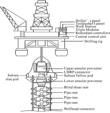
Figure 1.Typical architecture of a subsea BOP system[3]
The subsea BOP stack is usually equipped with two hydraulic connectors,the LMRP connector and the well head connector.The LMRP connector is located in the middle of two annular preventers,which is used to connect the LMRP to the BOP stack.The well head connector is used to connect the BOP stack to the well head.
The annular preventers,ram preventers,connectors,and other components such as the flexible joint,choke/kill valves,and choke/kill lines are integrated to form the whole subsea BOP stack.
3.System model in SimulationX
SimulationX contains a library of generic models for components and valves that are included in the most common deepwater systems.Moreover,it provides lots of basic hydraulic and mechanical elements,which makes it easy to set up a tailored complicated model such as the subsea BOP stack system.
3.1.Annularblowoutpreventer
An annular-type blowout preventer can close around the drill string,casing or a non-cylindrical object,such as the kelly.Annular blowout preventers are also effective at maintaining a seal around the drill pipe even as it rotates during drilling.
An annular blowout preventer uses the principle of a wedge to shut in the wellbore.Figure 2 shows the photo of an annular preventer.It has a donut-like rubber seal,known as an elastomeric packing unit,reinforced with steel ribs.The packing unit is situated in the BOP housing between the head and hydraulic piston.When the piston is actuated,its upward thrust forces the packing unit to constrict,sealing the annulus or open hole.Annular blowout preventer uses a “wedge-faced” (conical-faced) piston.As the piston rises,vertical movement of the packing unit is restricted by the head and the sloped face of the piston squeezes the packing unit inward,toward the center of the well bore.Forces acting on the piston during its actuation are shown in Figure 3.Where,q3andq4represent the working pressure and the well pressure,respectively[4].
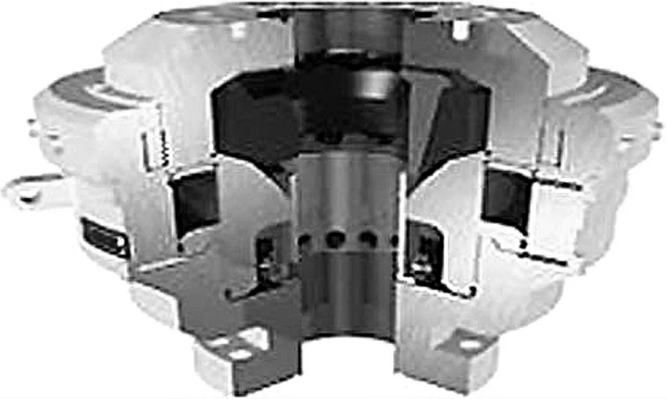
Figure 2.Annular blowout preventer
The elasticity of packing unit in annular preventer is estimated by using finite element method.It is assumed that the last 3% of stroke is used to squeeze the packing unit around pipe.The estimated behavior of the annular element is shown in Figure 4.
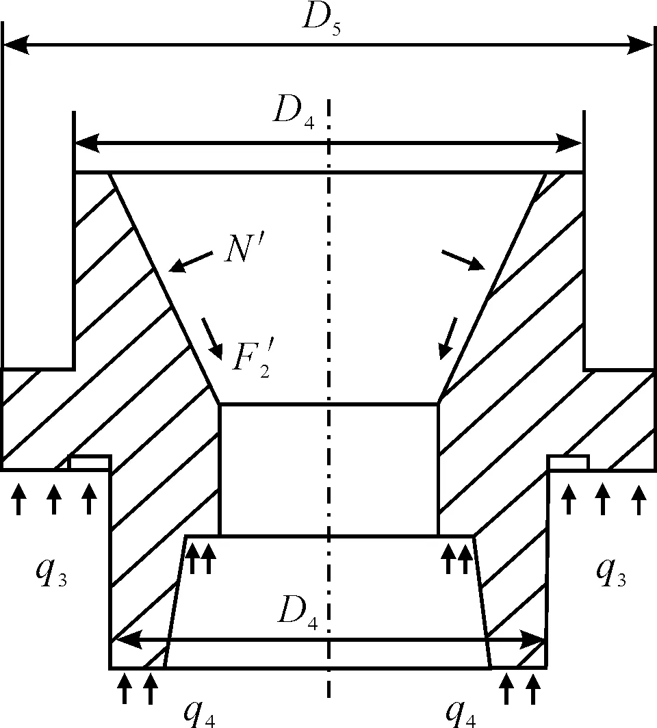
Figure 3.Piston in annular preventer
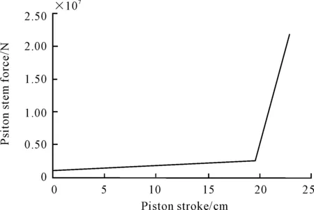
Figure 4.Annular preventer compression force
Figure 5 presents the model for an annular preventer.The model comprises elements from SimulationX library that are dedicated to hydraulics,in conjunction with the elements from the mechanical library.Annular preventer control pod is simplified into a hydraulic control system comprising of necessary elements including pressure regulator,directional valves and hose lines.
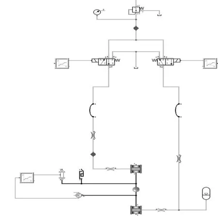
Figure 5.Model for an annular preventer
3.2.Ramblowoutpreventer
A ram-type blowout preventer is similar in operation to a gate valve,but uses a pair of opposing steel plungers,rams.The rams extend toward the center of the wellbore to restrict flow or retract open in order to permit flow.The inner and top faces of the rams are fitted with packers (elastomeric seals) that press against each other,against the wellbore,and around tubing running through the wellbore.Figure 6 shows a typical ram blowout preventer.
Rams are of four common types such as pipe,blind,shear and blind shear.In addition to the standard ram functions,variable-bore pipe rams are frequently used as test rams in a modified blowout preventer device known as a stack test valve.Ram blowout preventers for use in deepwater applications universally employ hydraulic actuation.Threaded shafts are often still incorporated into hydraulic ram preventers as lock rods that hold the ram in position after hydraulic actuation.By using a mechanical ram locking mechanism,constant hydraulic pressure need not be maintained.Other types of ram locks,such as wedge locks,are also used.
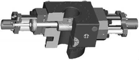
Figure 6.Ram blowout preventer
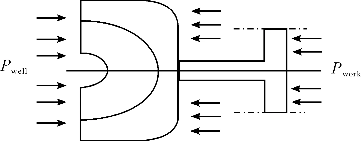
Figure 7.Piston in ram preventer
Pressure exerting on the piston in ram preventer is shown in Figure 7[4].The model for a ram preventer is presented in Figure 8.Wedge lock is adopted in the model.The ram preventer control pod is also simplified into a hydraulic system comprising of necessary elements including pressure regulator,directional valves and hose lines.
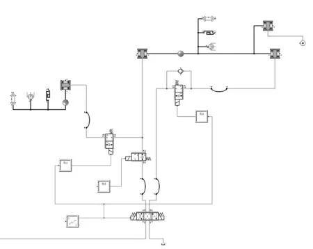
Figure 8.Model for a ram preventer
4.Simulation results
The main task of this study is to understand the subsea hydraulic system behavior of BOP stacks under normal conditions and verify whether it is appropriate to be operated according to API requirements at the water depth of 1 524 m.The closing times of API are 45 seconds for ram preventer and 60 seconds for annular preventer.
The evaluated system is similar to that used in Deepwater Horizon.There are three hydraulic pumps at the water surface providing the required working pressure.The length of the rigid conduit line is 1 524 m with the outer diameter 88.9 mm.The total effective gas volume of LMRP accumulators is 908 L and the pre-charge pressure is 27.6 MPa.
One important enquiry is to determine if the system capacity is capable to operate several actuator functions in series or parallel at the required water depth.Cases taking into account of different operation sequences of blowout preventers are simulated and the results with time plot are presented in details.
4.1.Closingupperandlowerannularpreventersinseries
In this case,upper annular preventer (UAP) is actuated to close when the time is 2 s.At the end of its actuation,lower annular preventer (LAP) started to be closed when the time is 32 s.The pressure regulator in the control pod is set to 10.3 MPa which adds the static head pressure.
Figure 9 shows the pressure trends and actuator positions for two annular preventers.The required closing time from starting to be closed until the packing unit reaches the pipe is simulated to be 22 s for each annular preventer.The annular preventer packing unit is set up to close around the pipe at the last 3% of stroke.That is where the regulator pressure starts to rise again.
The LMRP accumulators are pre-charged with nitrogen gas to 27.6 MPa at 20 ℃ at surface and charged to 34.5 MPa added static head pressure.When the two annular preventers are operated,the LMRP accumulator oil volume drops to the minimum of 294 L including 3.8 L dead volume as presented in Figure 10.At the same time,the supply pressure drops to the minimum of 43.3 MPa.
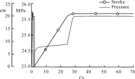

Figure 9.Pressure trends and actuator positions for UAP and LAP
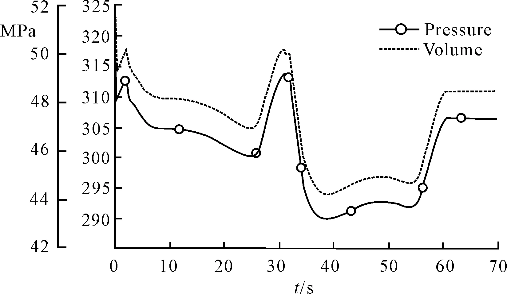
Figure 10.LMRP accumulator pressure and oil volume for series operation
Figure 11 shows the pump flow from the three surface HPU pumps while two annular preventers are operated in series.As can be seen,the three pumps are all actuated during the operation.
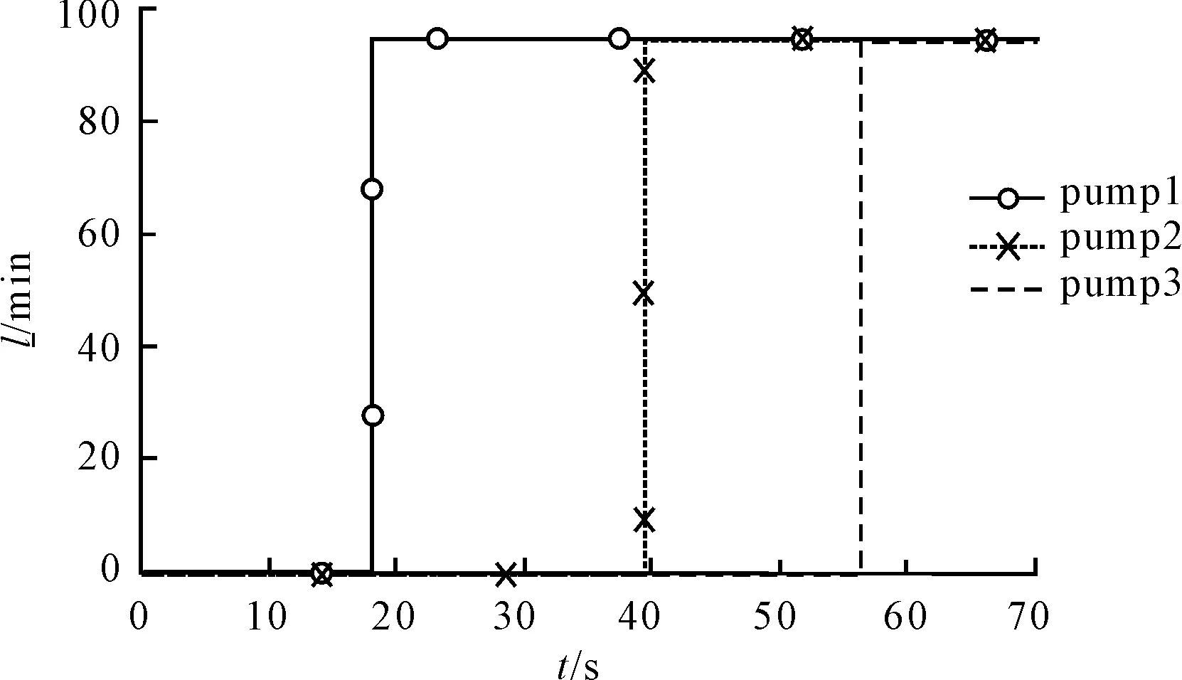
Figure 11.Surface pump flows for series operation
4.2.ClosingUAPfollowedbyLAPandonerampreventerinparallel
In this case,UAP is actuated to close when the time is at 2 s.At the end of its actuation,LAP and one ram preventer start to be closed when the time is at 42 s and 45 s,respectively.This opening sequence gives a parallel operation between the last annular preventer and the ram preventer.
The pressure regulators for annular preventers are set to the same as the last case,while for ram preventer it is set to 20.7 MPa added static head pressure.Figure 12 shows that all blowout preventers operate as expected and there is no sign of reduced system capacity from the preventer behavior.
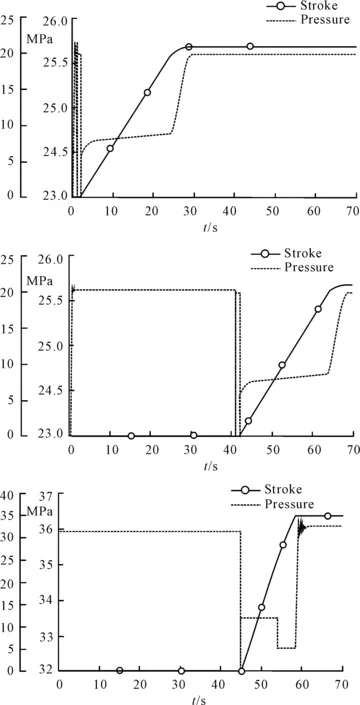
Figure 12.Pressure trends and actuator positions for parallel operation
When operating one annular preventer followed by a second annular preventer and a ram preventer in parallel,the LMRP accumulator oil volume drops to the minimum of 252 L,as shown in Figure 13.At the same time,the supply pressure drops to the minimum of 35.4 MPa.
Figure 14 shows the pump flow from the three surface HPU pumps while opening one annular preventer followed by a second annular preventer and a ram preventer in parallel.As can be seen,all three pumps start and together supply 284 L/min to the system.
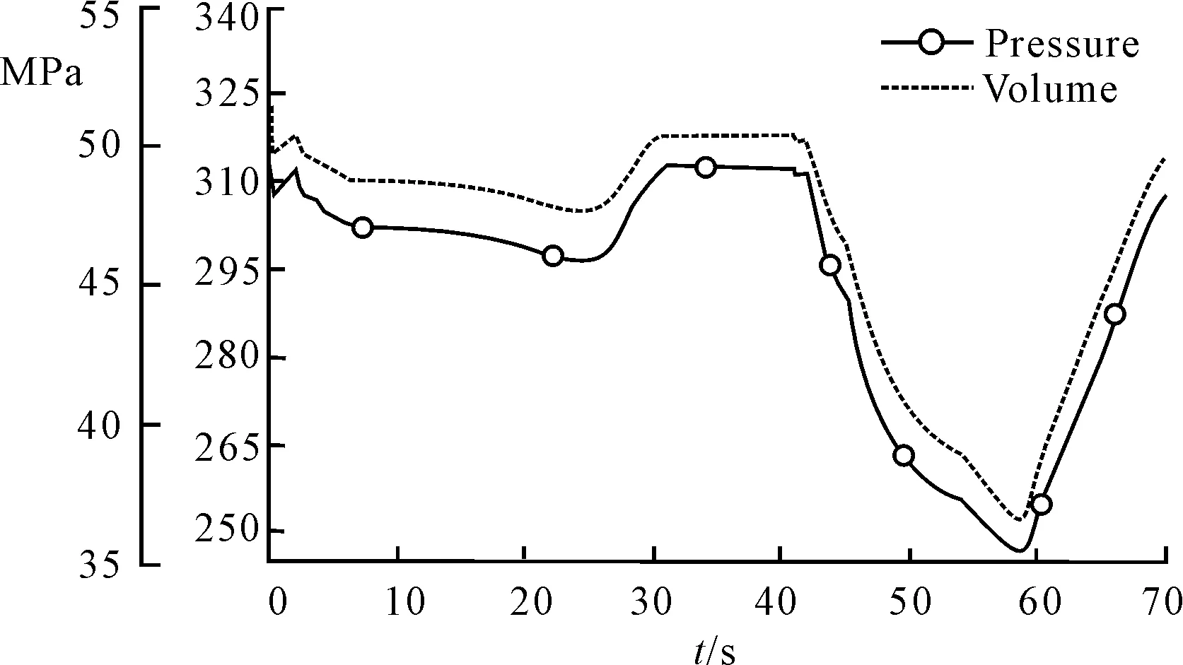
Figure 13.LMRP accumulator pressure and oil volume for parallel operation
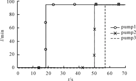
Figure 14.Surface pump flows for parallel operation
Other cases are also simulated including two ram preventers and the different operation sequences.Similar results show that all blowout preventers can operate as expected and there is no sign of reduced system capacity from the preventer behavior.
5.Conclusion
A complete model is set up to check if the evaluated subsea hydraulic system is appropriate to be operated according to API requirements at the water depth of 1 524 m.The simulation results show that the closing times for annular and ram preventers are both less than the specified values according to API.Moreover,with series or parallel operation,all blowout preventers can operate as expected and there is no sign of reduced system capacity from the preventer behavior.It is demonstrated that the evaluated hydraulic control system is appropriate to be operated at the water depth of 1 524 m.
[1]Khan M F.A critical review of well control procedures for the prevention of blowout (loss of kick)[D].Canada: Dalhousie University,2010.
[2]Harlow W F,Brantley B C,Harlow R M.BP initial image repair strategies after the Deepwater Horizon spill[J].Public Relat.,2011,Rev.37,80-83.
[3]Cai B P,Liu Y H,Liu,Z K,et al.Performance evaluation of subsea blowout preventer systems with common-cause failures[J].Journal of Petroleum Science and Engineering,2012(90/91): 18-25.
[4]Sun Z G.Research on parametric design and simulation technology for the blowout preventer[D].Beijing: China University of Petroleum,2009.
深水防噴器組液壓控制系統(tǒng)仿真
葛 斐?1,郭 宏2,李 博2,許 征1
1北京力合大科科技有限公司, 北京 100036;2中海油研究總院,北京 100027
井噴是海洋石油安全鉆探生產(chǎn)的重要威脅,人為操作失誤或元器件失效都可能導(dǎo)致井噴。防噴器組(BOP)安裝在水下井口頭,是控制井噴的核心部件,一旦發(fā)生井噴,BOP控制系統(tǒng)驅(qū)動(dòng)閥門關(guān)閉井口,保證油井的安全。研究了深水防噴器組包括其液壓控制系統(tǒng)的功能,在系統(tǒng)仿真軟件SimulationX中建立防噴器組的詳細(xì)模型,包括環(huán)形防噴器和閘板防噴器及防噴器組的液壓控制系統(tǒng)。仿真分析了1 524 m水深下防噴器在不同操作順序下的封井過程,驗(yàn)證了BOP閥門關(guān)閉所用時(shí)間符合API規(guī)范要求,仿真結(jié)果與平臺(tái)實(shí)測(cè)數(shù)據(jù)基本吻合。
深水鉆井;防噴器;液壓控制系統(tǒng);仿真
TM571.4
2013-10-20
? Fei GE,PhD.E-mail: gefei@gsimx.com
10.3969/j.issn.1001-3881.2014.06.013
猜你喜歡
流程工業(yè)(2022年3期)2022-06-23 09:41:10
流程工業(yè)(2022年3期)2022-06-23 09:41:08
流程工業(yè)(2022年3期)2022-06-23 09:41:02
流程工業(yè)(2022年3期)2022-06-23 09:40:50
流程工業(yè)(2022年5期)2022-06-23 07:19:22
流程工業(yè)(2022年5期)2022-06-23 07:19:16
中國(guó)核電(2021年3期)2021-08-13 08:57:02
中國(guó)石油石化(2021年8期)2021-07-20 07:36:12
煤氣與熱力(2021年3期)2021-06-09 06:16:18
智富時(shí)代(2018年5期)2018-07-18 17:52:04

- 機(jī)床與液壓的其它文章
- Investigation of helical ball micro milling with variable radial immersion*
- Numerical simulation of the double suction balance type screw compressor working process*
- Parameter optimization of electro-hydraulic proportionalsystem of PID based on the improved ant colony algorithm
- Flying cutter machining and cutter design based on the machining principle of cycloid rotational indexing
- Simulation of multi-modal control in electro-hydraulicposition servo-system*
- Optimal design and security verification of flying cutterbased on finite element analysis