A linear-to-circular polarization converter based on I-shaped circular frequency selective surfaces?
2017-08-30 08:25:34JiaLiangWu吳家梁BaoQinLin林寶勤XinYuDa達新宇andKaiWu吳凱
Chinese Physics B 2017年9期
Jia-Liang Wu(吳家梁),Bao-Qin Lin(林寶勤),Xin-Yu Da(達新宇),and Kai Wu(吳凱)
1 Information and Navigation College,Air Force Engineering University,Xi’an 710077,China
2 Air and Missile Defense College,Air Force Engineering University,Xi’an 710051,China
A linear-to-circular polarization converter based on I-shaped circular frequency selective surfaces?
Jia-Liang Wu(吳家梁)1,?,Bao-Qin Lin(林寶勤)1,Xin-Yu Da(達新宇)1,and Kai Wu(吳凱)2
1 Information and Navigation College,Air Force Engineering University,Xi’an 710077,China
2 Air and Missile Defense College,Air Force Engineering University,Xi’an 710051,China
In this paper,a linear-to-circular polarization converter using a three-layer frequency selective surface based on I-shaped circular structure resonant is presented and investigated.Numerical simulations exhibit that when the normal ypolarized waves impinge on this device propagating towards+z direction,the two orthogonal components of the transmitted waves have a 90°phase difference as well as the nearly equal amplitudes at the resonant frequency of 7.04 GHz,which means that the left-hand circular polarization is realized in transmission.For validating the proposed design,a prototype which consists of 25×25 elements has been designed,manufactured and measured.The measured results are in good agreement with the simulated ones,showing that the polarization conversion transmission is over?3 dB in the frequency range of 5.22–8.08 GHz and the axial ratio is below 3 dB from 5.86 GHz to 7.34 GHz.
polarization converter,metasurface,frequency selective surface
1.Introduction
Circularly polarized(CP)wave is preferred in many applications,such as long distance communication and remote sensing systems,in terms of its simplified transmitter–receiver alignment and its robustness against the environment interference.For this purpose,a variety of CP antennas have been carried out in the literature.[1–4]Conventional methods to realize circular polarization consist of introducing radiating systems with a planar array and special feed configurations.An alternative approach of generating CP waves is to insert a LP-to-CP converter on top of linearly polarized(LP)array,which can convert LP waves to the CP ones effectively.Therefore,a lot of efforts have been conducted to manipulate the polarization state of EM waves.Conventional devices for polarization conversion are mainly designed by using the optical gratings and birefringent materials.However,such methods generally lead to the bulky volume,which prevents the polarization converter being applied to particular engineering systems.
Metasurface is a two-dimension equivalent of material, which has been investigated widely for their unique electromagnetic and optical properties over the past decades.[5–9]Recently,metasurface has been considered as a particular case of broadband polarization converter based on open planar structure for high-gain antenna system.This structure can be implemented by using frequency selective surfaces(FSS)which provide different transmission characteristics of two orthogonal components of the incident LP waves.The FSS can be inductive impendence for one component and capacitive im-pendence for another component.Thus,a phase difference between two components of the transmitted wave can be obtained.If the two components have the same amplitude and the phase difference is equal to 90°,the incident LP wave can be transformed into a CP wave.For this case,different structures of FSS for LP-to-CP converters have been introduced in the literature,including cross-shaped dipoles,[10,11]spiltring slots,[12–15]meander lines,[16,17]T-shaped slots,[18]and bisected split-ring.[19]In spite of the advantages tendered by the aforementioned structures,they tend to be low-gain and operate at narrow bandwidth,which have still been the main shackle for particular applications.
In this paper,a novel I-shaped circular patch element is proposed to design the LP-to-CP polarization converter based on three-layer patch–aperture–patch(PAP)FSS.Ansoft HFSS software is used to model the element and investigate the performance of elements.By investigating the transmission characteristics for x-and y polarization,we present that the proposed device is competent to transmit incident LP waves into the CP ones.The proposed polarization converter can maintain a stable performance for the various incidence angles,and the simulation and measurement results are in good agreement.Compared to the previous designs in Refs.[10]–[19], the proposed polarization converter has a simpler-geometry but the wider axial ratio bandwidth,higher transmittance and less insertion loss,indicating that it may possess potential applications in the design of CP antennas.
2.Design of linear-to-circular polarization converter
Figure 1 illustrates the topology of the LP-to-CP converter.This device is an anisotropic structure,which can convert the incident LP wave into a CP wave.Consider an incident normal y-polarized LP wave Ei,which travels towards the+z direction onto the polarization converter.The electric filed vector of the incident EM wave can be expressed as Ei=Ey=ayE0ejkz,and it can be decomposed into the vertical and horizontal components.The polarization converter behaves differently in frequency response of these two components.Therefore,the electric fields of the transmitted wave can be expressed as
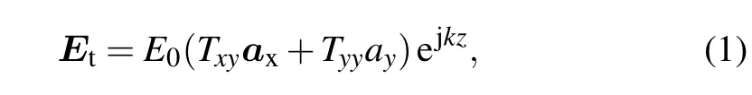
where E0represents the magnitude of the incident LP wave;axand ayindicate the unit vectors along the x-and y-directions, respectively;k represents the free space wave number;and jare defined to represent the transmission coefficients of the device for the x-and ypolarizations,respectively.To obtain a CP output wave within the operating frequency range,the amplitudes and phases of transmission coefficients Txyand Tyyshould be related based on
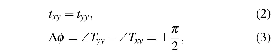
where Δφ represents the phase difference between y-and x component of the transmitted wave,which determines the form of the CP output wave.If Δφ=π/2,the transmitted wave is left-handed circular polarized(LHCP),while the transmitted wave is right-handed circular polarized(RHCP)if Δφ=?π/2.
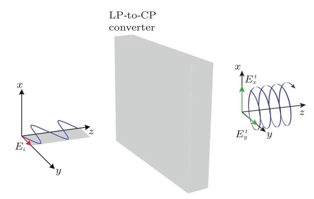
Fig.1.(color online)Schematic illustration of the linear-to-circular polarization under the incident normal y-polarized EM wave.
The unit cell of the proposed LP-to-CP converterisshown in Fig.2(a).It consists of two overlapped dielectric substrates separated by a metallic ground sheet with a small circular aperture to achieve a second-order band-pass response.[20,22]Based on the theory of PAP FSS,we combine the design idea of I-shaped circular micro-strip patches in the design of LP-to-CP converter.Two back-to-back I-shaped circular patches are printed on opposite sides of the dielectric substrates,and the geometry of the patch element is depicted in Fig.2(b).
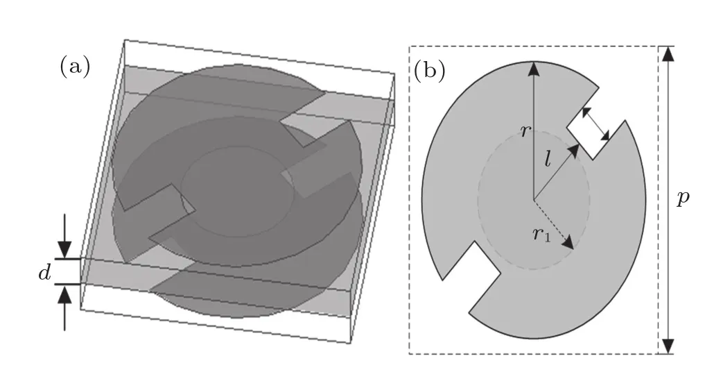
Fig.2.Unit cell of the proposed polarization converter with(a)3D view and(b)top view.
To elucidate the operation principle of the polarization converter based on three-layer PAP FSS,the electric field of y-polarized incident LP wave Eion the top patch will be developed,as shown in Fig.3(b).Since the proposed metasur-face is an anisotropic structure with a pair of mutually perpendicular symmetric axis,the y-polarized incident wave can be resolved into two orthogonal components E1and E2.The equivalent circuit model of the radiative element valid for the components E1and E2are shown in Fig.4,where the middle structure resonator is an ensemble of coplanar-waveguide (CPW)resonator.In this circuit model,the components E1and E2will see the new unit cell with the impendences Z1and Z2,respectively,given by

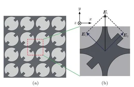
Fig.3.(color online)(a)Top patches of the polarization converter.(b) New unit cell of the top patches.
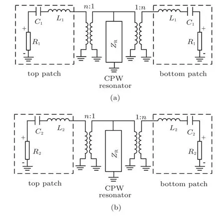
Fig.4.Equivalent circuit model of the polarization converter seen by(a) E1 and(b)E2.
It can be seen from Fig.3 that there is a phase difference between Z1and Z2due to the different gap spacing between diagonal patches.Since the impendence Z1is less capacitive and more inductive than Z2,the components E1will lead E2by ang(Z1?Z2)after going through the top patch.If|Z1|=|Z2| and ang(Z1?Z2)=90°by adjusting the dimensions of the patches,the y-polarized incident LP wave can be converted into a LHCP one.
In addition,based on the design in Ref.[23],we introduce the circular structure into the CPW resonator to obtain a second-order band-pass response.The CPW resonator and two patches are coupled at localized coupling points,where the CPW resonator structure can be altered to carry a net magnetic current,and the dimension of CPW resonator determines the coupling degrees.In the circuit model,the two patches are modeled as two series LC resonators,and the circular aperture presents a resonance at the center frequency.Therefore, we combine the design idea of I-shaped circular micro-strip patches and the theory of PAP FSS to design LP-to-CP converter.By adjusting the dimensions of the patches as well as the dimension and position of the aperture,an incident lineal EM wave at the certain frequency can be received effectively by the upper micro-strip patch,and the transmission wave as the radiant wave of the nether micro-strip patch would be the circularly polarized one.
In this design,the repetition period of the unit cell is p= 12 mm,the radius of the circular patch element is r=5.5 mm, and the radius of the circular aperture is r1=3.6 mm.The geometrical parameter w is the width of the slot in the I-shaped circular patch,and l is the length from the center of patch to the slot.The thickness of both two dielectric substrate is d=1.8 mm,and the relative dielectric constant and loss tangent are εr=2.65 and tanδ=0.001,respectively.In addition, the thickness of the metallic groundsheet is t=0.017 mm.
For investigating the performance of our design,the element is simulated by using the commercial full-wave electromagnetic solver Ansoft HFSS.Periodic boundaries and Floquet mode excitations are introduced to implement the infinitearray approach for element analysis.In order to obtain better performance of the proposed polarization converter,a parameter study is implemented to evaluate the effects of the parameters w and l on the axial ratio(AR)at different frequencies. The AR of the transmitted wave can be calculated by
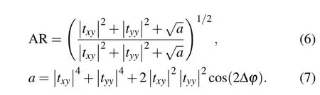
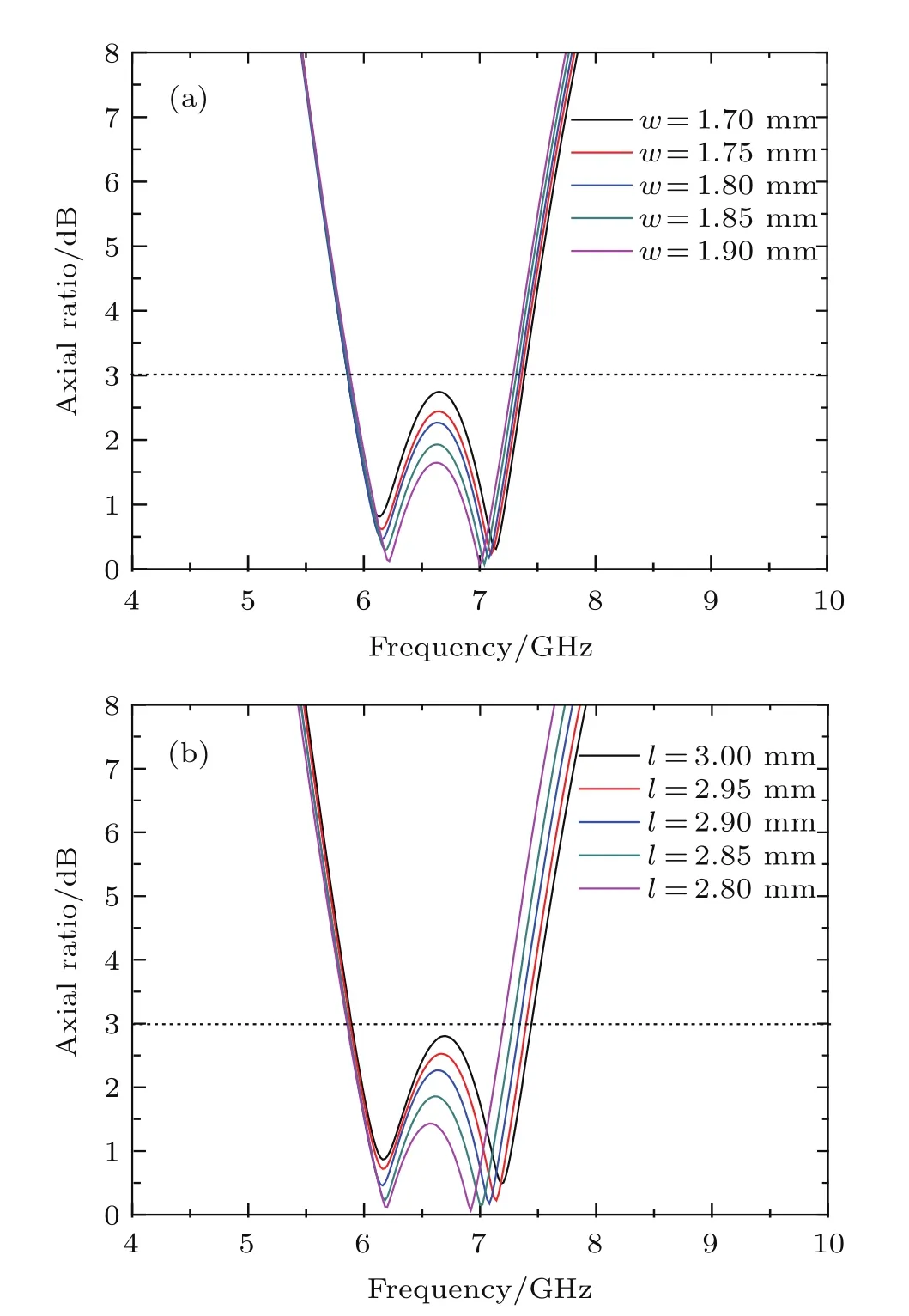
Fig.5.(color online)Simulated results of the axial ratio with different(a) w and(b)l.
The calculated AR versus different parameters w andlare shown in Fig.5(a)and 5(b),respectively.From the optimization process,it can be found that the AR curves have two lowest dips at around 6.2 and 7.1 GHz.The blue curves show the AR performance by using the optimized parameters, and the dimensions for these parameters are w=1.8 mm and l=2.9 mm.It can be seen clearly that AR is lower than 3 dB in the frequency range from 5.86 GHz to 7.34 GHz,and it has two lowest dips of 0.46 and 0.17 dB at 6.16 and 7.08 GHz, while a peak of 2.27 dB at 6.64 GHz between the two lowest dips.
As shown in Fig.5(a),when the parameter w is decreased from 1.8 mm to 1.7 mm by 0.05 mm,the frequency range of 3-dB AR remains almost the same,but the values of two lowest dips are larger,while the peak between the two lowest dips goes higher.When the parameter w is increased from 1.8 mm to 1.9 mm by 0.05 mm,the values of two lowest dips and in band peak are a littler smaller,but the frequency range of 3-dB AR is narrower.Figure 5(b)shows that,when the parameterlis decreased from 2.9 mm to 2.8 mm by 0.05 mm,the values of two lowest dips and in-band peak are a littler smaller,but the frequency range of 3-dB AR is much narrower.Whenlis increased from 2.9 mm to 3 mm by 0.05 mm the frequency range of 3-dB AR remains almost the same,but the values of two lowest dips are larger,while the in-band peak goes higher.Considering the factors of 3-dB axial ratio bandwidth (ARBW)and the minimum AR value,we select the element with geometrical parameters of w=1.8 mm and l=2.9 mm for our design.
3.Simulation and analysis
As for the designed polarization converter,numerical simulation was performed by using Ansoft HFSS.The simulated results under y-polarized EM wave normal incidence from+z direction are presented in Fig.6,where rxyand ryyrepresent the amplitudes of reflection coefficients for x-and y-polarization,respectively.As shown in Fig.6(a),the amplitudes of reflection coefficients rxyand ryyare both close to zero around the resonant frequency of 7.04 GHz,while the values of txyand tyyare nearly unity.In addition,from Fig.6(b)it can be seen that the phase difference Δφ is very close to 90°at the frequency of 7.04 GHz,which means that a nearly pure CP wave is obtained.Thus,it can be concluded that the ypolarized wave is converted into a LHCP one at the frequency of 7.04 GHz.
To assess the performance of the proposed polarization converter at different frequencies,we consider the axial ratio AR and total transmittance T.The axial ratio and total transmittance can be calculated respectively by using Eq.(6)and
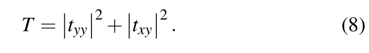
Figure 7 presents the calculated results of the axial ratio and total transmittance.It can be seen that the total transmittances areall over?3 dB in the frequency range from 5.22 GHz to 8.08 GHz,corresponding to a relative bandwidth of43%.Besides,in the frequency range of5.86–7.34 GHz,the values of maximum and minimum insertion loss are 2.47 dB at 5.86 GHz and 0.007 dB at 6.96 GHz,respectively.The bandwidth of 3-dB axial ratio is about 22.4%from 5.86 GHz to 7.34 GHz,while the axial ratio at the resonant frequency of 7.04 GHz is about 0.39 dB.

Fig.6.(color online)Simulated results of the polarization converter at ypolarized normal incidence.(a)The magnitudes of cross and co-polarized reflection and transmission coefficients.(b)The phase difference between the co-polarization and cross-polarization transmitted waves.
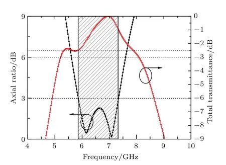
Fig.7.(color online)Simulated results of axial ratio and total transmittance at y-polarized normal incidence.
To evaluate the response of the proposed polarization converter to the angle of incidence,simulations have been carried out under different angles of incidence.The calculated results of total transmittance,together with the axial ratio for various angles of incidence from 0°to 60°in x–z plane are shown in Fig.8.It can be observed that for incidence angle in the range of 0°–45°,the proposed polarization converter operates in a relatively stable situation in term of total transmittance and axial ratio.When the incidence angle increases to 60°,the total transmittance of the transmitted signal is depressed quickly with a minimum insertion loss of 0.68 dB at 7.3 GHz.In addition,the frequency range of 3-dB axial ratio is from 6.02 GHz to 7.28 GHz with a relative bandwidth of 18.9%.
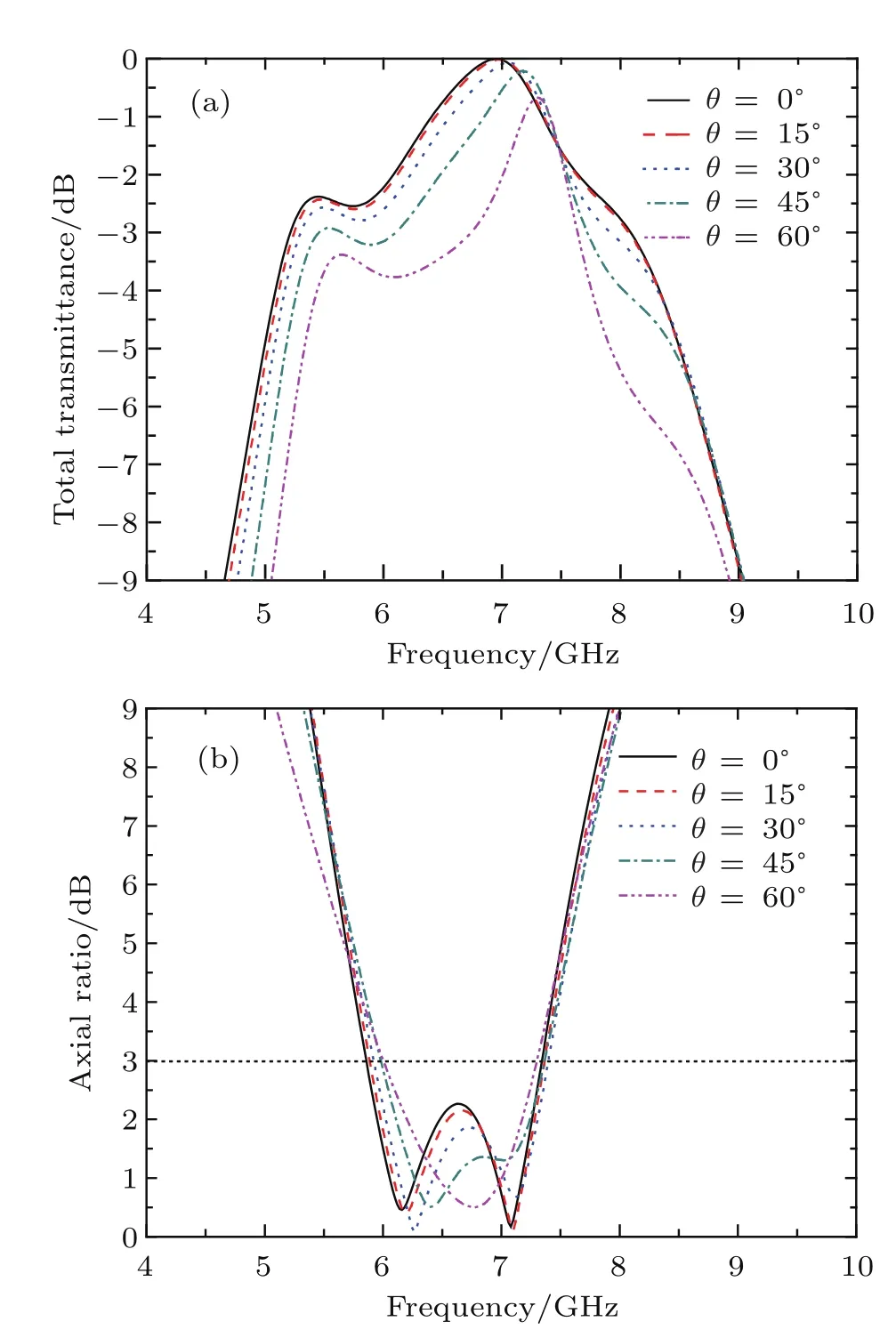
Fig.8.(color online)Response of the proposed polarization converter for various angles of incidence:(a)total transmittance and(b)axial ratio.
4.Experimental validation
In order to validate the performance of the proposed polarization converter,a sample containing 25×25 unit cells with the size of 300×300 mm2is fabricated by using printed circuit board(PCB)technique,and the photograph of the fabricated prototype is shown in Fig.9.The measurement setup contains two standard gain horn antennas both connected to the two ports of an Agilent E8363B network analyzer.One horn antenna acts as a transmitter while the other one acts as a receiver.The fabricated prototype is placed between the two horn antennas.The frequency responses of the fabricated prototype were measured under the normal incident y-polarized wave in a frequency range of 4–10 GHz,and the axial ratio was calculated by using Eq.(4).The simulated and measured results of the total transmittance and axial ratio are plotted in Fig.10.It is found that a good accordance between the measured results and the simulated ones is obtained.It should be pointed out that the random phase error,losses in elements and substrate,blockages of gain horn antennas and measurement errors could affect the performance of polarization converter negatively.
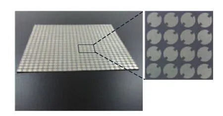
Fig.9.Photograph of fabricated prototype.

Fig.10.(color online)The comparison between the measured and simulated results of(a)total transmittance and(b)axial ratio.
5.Conclusion
In this work,we have proposed a linear-to-circular polarization converter based on three-layer PAP FSS.A novel I-shaped circular patch element has been introduced and optimized to achieve a desirable radiation performance.Numerical simulations exhibit that the polarization conversion transmission is over 3 dB in the frequency range of 5.22–8.08 GHz, while the minimum insertion loss is only 0.007 dB.The axial ratio is below 3 dB from 5.86 GHz to 7.34 GHz.The frequency response of the proposed device is stable for the various incidence angles from 0°to 45°.A prototype of the polarization converter was fabricated and experimentally validated. The measured results and the simulated ones are in good accordance,indicating that the proposed polarization converter possesses the ability to generate CP signals for particular engineering systems.
[1]Li T J,Liang J G,Li H P and Liu Y Q 2016 Chin.Phys.B 25 094101
[2]Li W H,Zhang J Q,Qu S B,Shen Y,Yu J B,Fan Y and Zhang A X 2016 Acta Phys.Sin.65 024101(in Chinese)
[3]Cong L L,Fu Q,Cao X Y,Gao J,Song T,Li W Q,Zhao Y and Zheng Y J 2015 Acta Phys.Sin.64 224219(in Chinese)
[4]Zhang H L,Hu B J and Zhang X Y 2012 Chin.Phys.B 21 027701
[5]Alqadi M K and Alzoubi F Y 2014 Chin.Phys.B 23 087506
[6]Guo W J,Chen Z G,Cai L B,Wang G Q and Cheng G X 2015 Acta Phys.Sin.64 070702(in Chinese)
[7]Li L Y,Wang J,Du H L,Wang J F and Qu S B 2015 Chin.Phys.B 24 064201
[8]Heng H and Yang L 2014 Chin.Phys.B 23 068101
[9]Han J F,Cao X Y,Gao J,Li S J and Zhang C 2016 Acta Phys.Sin.65 044201(in Chinese)
[10]Kiani G and Dyadyuk V 2012 Antennas and Propagation Society International Symposium(APSURSI),July,2012,Chicago,USA,p.1
[11]Sohail I,Ranga Y,Esselle K and Hay S 2013 European Conference on Antennas and Propagation(EuCAP’13),April,2013,Goteborg,Sweden,p.2141
[12]Euler M,Fusco V,Cahill R and Dickie R 2010 Microw.Antennas Propag.4 1764
[13]Euler M,Fusco V,Cahill R and Dickie R 2010 IEEE Trans.Antennas Propag.58 2457
[14]Wang J,Wu W and Shen Z X 2014 Antennas and Propagation Society International Symposium(APSURSI),July,2014,Memphis,USA,p.1
[15]Yan S and Vandenbosch G A E 2013 Appl.Phys.Lett.102 103503
[16]Letizia M,Fuchs B,Zorraquino C,Zurcher J F and Mosig J R 2012 Prog.Electromagn.Res.B 45 309
[17]Joyal M and Laurin J 2012 IEEE Trans.Antennas Propag.60 3007
[18]Biscarini M,Sardi G M,Maritini E,Caminita F and Maci S 2013 European Conference on Antennas and Propagation(EuCAP’13),April, 2013,Goteborg,Sweden,p.1
[19]Martinez-Lopez L,Rodriguez-Cuevas J,Martinez-Lopez J I and Martynyuk A E 2014 IEEE Antennas Wireless Propag.Lett.13 153
[20]Abbaspour-Tamijani A,Schoenlinner B,Sarabandi K and Rebeiz G M 2003 Antennas and Propagation Society International Symposium 2 817
[21]Tamijani A A,Sarabandi K and Rebeiz G M 2004 IEEE Trans.Microw. Theory Tech.52 1781
[22]Cui T,Huang J Z,Liu X and Zeng G H 2016 Chin.Phys.B 25 020301
[23]Zhou H,Qu S B,Xu Z,Wang J F,Ma H,Peng W D,Lin B Q and Bai P 2011 IEEE Antennas Wireless Propag.Lett.10 507
19 November 2016;revised manuscript
20 April 2017;published online 11 August 2017)
10.1088/1674-1056/26/9/094201
?Project supported by the National Natural Science Foundation of China(Grant Nos.61471387,61271250,and 61571460).
?Corresponding author.E-mail:wujia2538@126.com
?2017 Chinese Physical Society and IOP Publishing Ltd http://iopscience.iop.org/cpb http://cpb.iphy.ac.cn

- Chinese Physics B的其它文章
- Relationship measurement between ac-Stark shift of 40Ca+clock transition and laser polarization direction?
- Air breakdown induced by the microwave with two mutually orthogonal and heterophase electric field components?
- Collective motion of active particles in environmental noise?
- Temperature dependence of heat conduction coefficient in nanotube/nanowire networks?
- Analysis of dynamic features in intersecting pedestrian flows?
- Heat transfer enhancement in MOSFET mounted on different FR4 substrates by thermal transient measurement?