Study of Design and Construction Technology of Ultra-large-span Tunnel at Badaling Great Wall Station
2018-04-19 06:49:06ZHANGMinqingLYUGangHEZhijunLIUJianyouJIAOYunzhouLUODuhao
隧道建設(shè)(中英文) 2018年3期
關(guān)鍵詞:一致性
ZHANG Minqing, LYU Gang, HE Zhijun, LIU Jianyou, JIAO Yunzhou, LUO Duhao
(1. Engineering Management Center of China Railway Corporation, Beijing 100844, China;2. China Railway Engineering Consulting Group Co., Ltd., Beijing 100055, China;3. China Railway No.5 Engineering Group Co., Ltd., Changsha 410117, Hunan, China)
0 Introduction
With the development and utilization of underground spaces, people are building increasing numbers of large-span and large-section underground works, especially urban underground stations, to support the application functions. In general, tunnels are classified as small-span (excavation span of 5 m to 8.5 m), middle-span (excavation span of 8.5 m to 12 m), large-span (excavation span of 12 m to 14 m), extra-large-span (excavation span of 14 m to 16 m), and ultra-large-span (excavation span of more than 16 m)[1-3].
Larger tunnel excavation span and section area lead to more difficult excavation and higher construction safety risk[4-6]. For tunnels with a large span and section, there are three critical factors ensuring safe construction, i.e., the support system design, excavation method determination, and surrounding rock deformation control. To study the process of progressive destruction of the surrounding rock of ultra-large-span tunnels growing with the increase of their buried depth, Li et al.[7]used the test system of a large 3D geological mechanical model with uniform gradient loading and developed materials similar to weak, broken surrounding rock and its support system to conduct a large-scale model test. This provided a true representation of the full process of the progressive destruction of the surrounding rock of sections built by the full-face excavation method and bench cut method as well as the weak, broken surrounding rock of the working face retaining section. To master the deformation features of the large-section tunnel in the stratum of the Xigeda Formation and ensure stability of the surrounding rock during construction of the large-section tunnel, Wang et al.[8]studied the time-space effect of the deformation of the large-section tunnel in the stratum of the Xigeda Formation during construction using the temporary 3-bench inverted arch method; this was based on the reconstruction of the Tongzilin Tunnel of the Panzhihua-Miyi Section of Chengdu-Kunming Railway and used the method combining numerical simulation and multi-section site monitoring. Jiang et al.[9]studied the 8-lane ultra-section tunnel of an expressway and developed an optimized design scheme and construction procedure based on structural calculation and engineering analogy. Based on the loess tunnel works of the Zhengzhou-Xi′an Passenger-dedicated Railway, Gao[10]provided reasonable directions for the design and construction of large-section shallow-buried loess tunnels and set forth a construction method that can reduce surface cracks. Teng[11]proposed several technical solutions for the construction of large-section shallow-buried tunnels in soft plastic clay in northeastern cold areas and determined the best solution upon comparison. Using the methods of theoretical analysis, site testing and numerical research, Zhang[12]conducted an optimization study of both the surrounding rock deformation features and the construction parameters of large-section shallow-buried tunnels and determined the major factors leading to surrounding rock deformation.
As described above, in the past, for large-section tunnel construction, steel frames, shotcrete and system rockbolts were typically used as the primary support system and the temporary 3-bench inverted arch method (large-section tunnels) or dual-side heading method (ultra-section tunnels) was adopted. The study of deformation control during construction based on two control criteria (total deformation and deformation in steps) was absent. In the present paper, by taking the large-span transition section tunnel at Badaling Great Wall Station of the new Beijing-Zhangjiakou Railway as an example, a new support design idea, new excavation method, and dual principles and criteria for surrounding rock deformation control of undercut tunnels with an ultra-large span and ultra-large section are studied.
1 Project overview
The new Badaling Tunnel is 12.01 km in length and is the longest tunnel of the new Beijing-Zhangjiakou Railway. Badaling Great Wall Station is an underground station within the new Badaling Tunnel. The tunnel is below the Guntiangou Parking Lot of the Badaling Scenic Spot and is adjacent to the Badaling Great Wall. With a buried depth of 102 m. The station is the high-speed railway station with the largest buried depth in the world.
With a total length of 470 m and underground floor area of approximately 36 000 m2, the station has a 3-level underground structure,i.e., the platform level, entrance level and exit level from the bottom to the top. At the platform level, there are a total of 5 parallel tunnels, including the excavation passages on both sides of the station. In total, the station has 78 chambers with 88 section types. The intersections of the chambers are dense. The minimum horizontal interval and vertical interval between the chambers are 2.27 m and 4.45 m, respectively. The building structure is very complicated, making the station the underground station with the most complicated building structure in the world.
As shown in Figs. 1, 2 and 3, a 163-m large-span transition section is set at each end of the Badaling Great Wall Station; it is connected to the main-track tunnel via the transition sections. The transition section is the traffic tunnel with the largest excavation span (32.7 m) and excavation section area (494.4 m2) in the world, resulting
in great construction difficulty and high safety risk. Table 1 shows the statistics of traffic tunnels with ultra-large span and ultra-large section both in China and abroad.
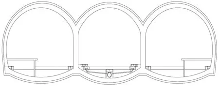
Fig. 1 Badaling Great Wall Station
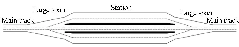
Fig. 2 Alignment of Badaling Great Wall Station
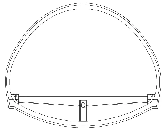
Fig. 3 Large-span section of Badaling Great Wall Station
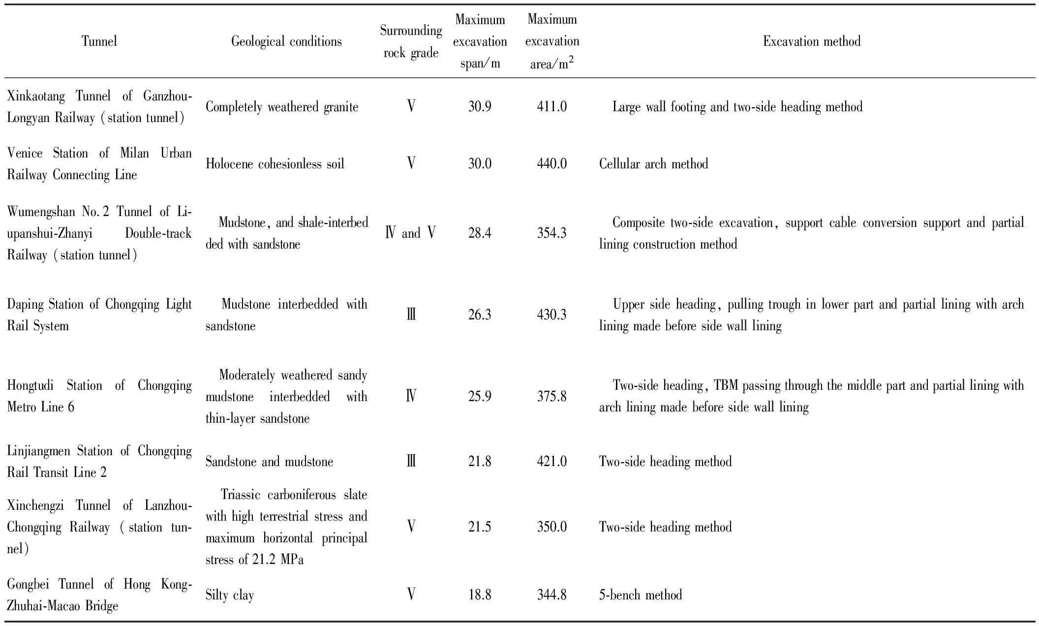
TunnelGeologicalconditionsSurroundingrockgradeMaximumexcavationspan/mMaximumexcavationarea/m2ExcavationmethodXinkaotangTunnelofGanzhou?LongyanRailway(stationtunnel)CompletelyweatheredgraniteⅤ30.9411.0 Largewallfootingandtwo?sideheadingmethodVeniceStationofMilanUrbanRailwayConnectingLineHolocenecohesionlesssoilⅤ30.0440.0CellulararchmethodWumengshanNo.2TunnelofLi?upanshui?ZhanyiDouble?trackRailway(stationtunnel) Mudstone,andshale?interbeddedwithsandstoneⅣandⅤ28.4354.3 Compositetwo?sideexcavation,supportcableconversionsupportandpartialliningconstructionmethodDapingStationofChongqingLightRailSystem MudstoneinterbeddedwithsandstoneⅢ26.3430.3 Uppersideheading,pullingtroughinlowerpartandpartialliningwitharchliningmadebeforesidewallliningHongtudiStationofChongqingMetroLine6 Moderatelyweatheredsandymudstoneinterbeddedwiththin?layersandstoneⅣ25.9375.8 Two?sideheading,TBMpassingthroughthemiddlepartandpartialliningwitharchliningmadebeforesidewallliningLinjiangmenStationofChongqingRailTransitLine2SandstoneandmudstoneⅢ21.8421.0Two?sideheadingmethodXinchengziTunnelofLanzhou?ChongqingRailway(stationtun?nel) Triassiccarboniferousslatewithhighterrestrialstressandmaximumhorizontalprincipalstressof21.2MPaⅤ21.5350.0Two?sideheadingmethodGongbeiTunnelofHongKong?Zhuhai?MacaoBridgeSiltyclayⅤ18.8344.85?benchmethod
2 Engineering geology and hydrogeology
The site of Badaling Station is in the Jundushan Low-and Medium-Mountain Areas, which are characterized by large land undulation and developed gullies; overall landform is high in the northeast and low in the southwest. The ground elevation generally ranges from 600 m to 1 030 m, with an elevation difference between 200 m and 400 m. The lush vegetation is dominated by shrubs. The granite complex of Badaling medium-size stock developing in the scope of the station is distributed in the Chadao Village-Qinglong Bridge area with outcrop of approximately 25 km2. The rock mass contacts the volcanic rock of Tiaojishan Formation and Donglingtai Formation on its north side, contacts the Yingwoliang rhyolite porphyry and Shanghuayuan quartz diorite on its east side and contacts the Donglaoyu granite, Xiqiaozi granite, and Mesozoic volcanic rock on its south side and west side, respectively. The granite is generally hard, with a saturated uniaxial compressive strength of 40 MPa to 60 MPa. The intrusive rock dikes of Badaling develop very well and exist in 10 forms: quartz porphyry dike, rhyolite porphyry dike, granite porphyry dike, diorite porphyrite dike, diabase dike, gabbro dike, orthophyre dike, Ivernite dike, alnoite dike, and eurite dike. With a width ranging from 2 m to 5 m, most of the dikes have an NNW strike, dipping eastwards with an angle of 60°- 70°. Table 2 shows the classification of the surrounding rock of the large-span transition section at the station.
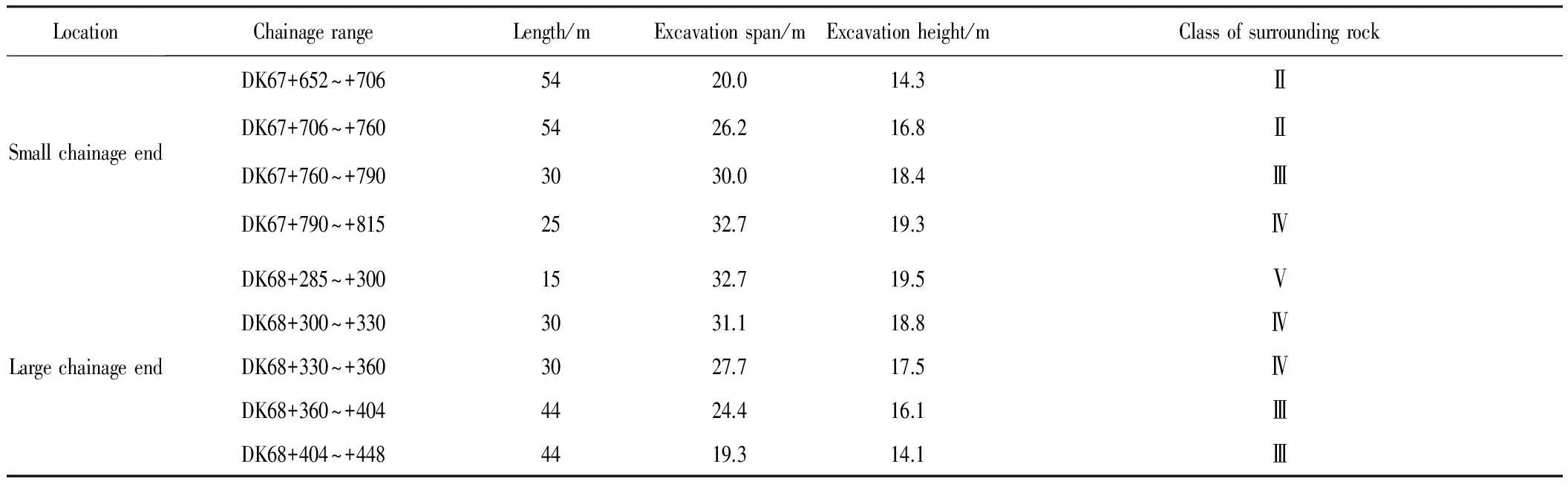
Table 2 Classification of surrounding rock of large-span transition section at station
In the station site area, the major geological structures are of the Yanshan Period, and fractures develop easily in these structures. The backbone is the NE fracture that is parallel to the Badaling box anticline axis accompanied by a NW fracture under horizontal tension nearly perpendicular to it. In addition, normal faults composed of nearly EW and nearly SN shear fracture faces and NNW shear fracture zones develop as well. In this area, fault F2 intersects the tunnel at DK68+260~+300, and the angle between it and the track is 35°. The fracture is a compresso-shear fracture with an attitude of 263°∠86°. Its hanging wall is of porphyritic monzonite granite, and its foot wall is of granite. There is crushed stone in the fault zone. There are 3 major sets of joints developing in the area. Groundwater in the area is bedrock fissure water with a normal yield of approximately 2 400 m3/d and a maximum yield of approximately 7 000 m3/d.
3 Design of the support system
With an excavation span of 19.3 m to 32.7 m, the large-span transition section at Badaling Station shows the features of ultra-large span and variable span. Therefore, based on the conventional method of "advance reinforcement, advance support, primary support, and secondary lining", a new definition was provided to each support function and a structural design and safety checking calculation for loads borne by the structure was conducted.
(1) Advance reinforcement and advance support. For class Ⅴ surrounding rock, the advance grouting reinforcement was employed to improve the surrounding rock and promote its cohesion and inner frictional angle. Support via pre-grouting with small ducts was used for classes Ⅲ and Ⅳ surrounding rock, and support by pipe umbrella was used for class Ⅴ surrounding rock to avoid separation and collapse, prevent formation of cavities and loose zones, and stabilize the self-supporting capacity of the surrounding rock during construction. The advance reinforcement and support were only used for safety and protection during the excavation and were not subject to checking calculation of loads borne by the structure.
(2) Steel frame support. In consideration of the large excavation span and large section of the tunnel, to avoid separation upon excavation, classes Ⅲ, Ⅳ and Ⅴ surrounding rocks were supported with grid steel frames for protection, which were not subject to checking calculation of loads borne by the structure.
(3) Anchor bolts, anchor cables and shotcrete. According to the theory of surrounding rock bearing arch, all the surrounding rock loads during the construction were borne by the bearing arch composed of anchor bolts, anchor cables, shotcrete and surrounding rock. Based on this theory, the safety checking calculation of loads borne by the structure was performed.
(4) Secondary lining. A service life of 300 years was designated for the operation period. In this case, the prestress of anchor bolts and cables as well as loads borne by reinforcing bars in the secondary lining were not taken into consideration. The loads borne by the secondary lining was calculated as a plain concrete structure. To enable the tunnel to achieve a 300-year service life, a 7-cm protective layer made of reinforcing bars was designed using raw materials such as moderate-heat cement, grade Ⅰ fly ash, shaped aggregate, and shrinkage-compensating material, and innovative technical measures including secondary concrete mixing, automatic intelligent vibration, and moisture protection with self-stick film were implemented.
3.1 Design of the support structure
See Table 3 for the design parameters of the support structure of the large-span transition section at Badaling Great Wall Station.
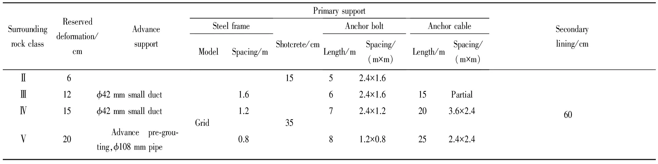
Table 3 Design parameters of support structure of large-span transition section at Badaling Great Wall Station
Remarks: (1) The spacing between anchor bolts and cables includes both the circumferential and longitudinal spacing. (2) According to the tunnel excavation span and classification of surrounding rock, 6-8 anchor cables were set for each excavation section in case of class Ⅲ surrounding rock, 13-15 were set in case of class Ⅳ surrounding rock, and 21-23 were set in case of class Ⅴ surrounding rock. (3) Depending on the engineering geology, a total of 92 anchor bolts were designed for the large-span section at the small chainage end and 603 were designed for the large-span section at the large chainage end. (4) A tension of 100 kN was set for prestressed anchor bolts and 1 000 kN was set for prestressed anchor cables. (5) Reinforced concrete was used for the secondary lining.
3.2 Checking calculation of loads borne by structures
3.2.1 Anchor bolt supporting force
It is calculated using the following formula.
(1)
wherepbis the anchor bolt supporting force (kPa),Fbis the designed tension of anchor bolts (kN),Sb1is the circumferential spacing between anchor bolts (m), andSb2is the longitudinal spacing between anchor bolts (m).
It is calculated using the following formula.
(2)
wherepais the anchor cable supporting force (kPa),Fais the designed tension of anchor cables (kN),Sa1is the circumferential spacing between anchor cables (m), andSa2is the longitudinal spacing between anchor cables (m).
3.2.3 Shotcrete supporting force
It is calculated using the following formula.
(3)
wherepsis the shotcrete supporting force (kPa),σsis the shotcrete shear strength (kPa), anddsis the shotcrete thickness (m).
3.2.4 Bearing arch thickness
It is calculated using the following formula.
(4)
wheredbis the bearing arch thickness (m),Lb1is the free end length of anchor bolts (m), andγis the curvature radius of the tunnel sides (m).
3.2.5 Safety factor
據(jù)相關(guān)調(diào)查結(jié)果顯示:在回答“我碰到問題首先找誰商量”時(shí),選擇同伴選項(xiàng)的占70%,選擇父母的占10%,選擇老師的占8%,選擇其他的占12%。這表明,當(dāng)學(xué)生碰到麻煩時(shí),他們首先想到的是自己的同伴。社會(huì)心理學(xué)的研究證明,與在各方面接近自己的人交往,人們普遍更能打開話題,交友交心,因?yàn)槿穗H吸引具有一致性原則,相似的人更容易相互肯定,更容易進(jìn)行平等交往,也更能增強(qiáng)交往的效果。
It is calculated using the following formulas.
(5)
(6)
whereKarchcrownis the safety factor of arch crown,Ksidewallis the safety factor of side wall,Cgis the cohesion of medium-hard rock or soft rock upon improvement by grouting (kPa),φgis the inner frictional angle of medium-hard rock or soft rock upon improvement by grouting (°),His the excavation height of the tunnel (m),Lis the excavation width (span) of the tunnel (m),qis the vertical load (kPa), andkis the lateral pressure factor.
Checking calculation of the structural design safety factor of the large-span section (32.7 m) was conducted using the formulas above; the results are given in Table 4.
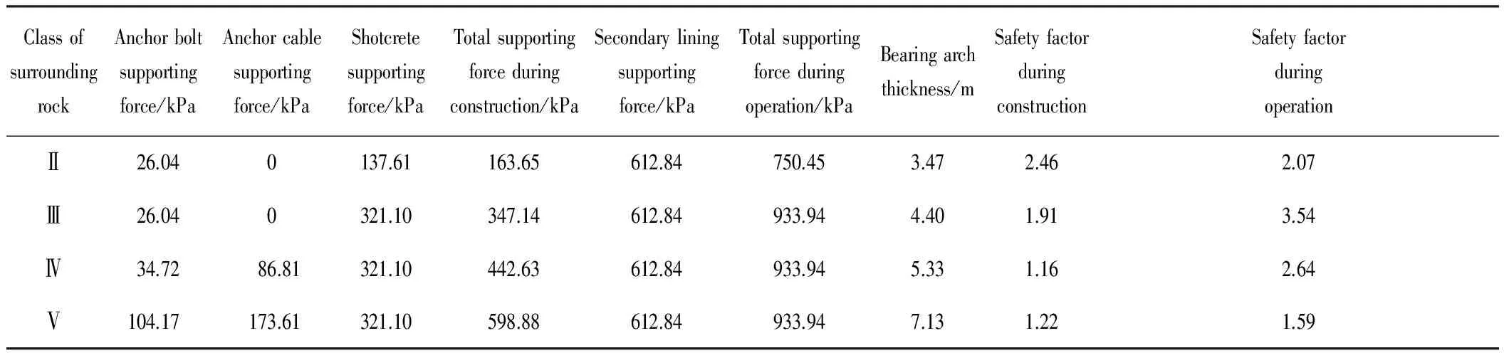
Table 4 Checking calculation of structural design safety factor of large-span transition section at Badaling Great Wall Station
According to the checking calculation, if the designed supporting parameters are adopted, then the tunnel structural design will be safe and reliable during construction and operation.
4 Tunnel excavation methods
In general, excavation methods applied to large-span and large-section tunnels are determined according to the engineering geology and the designed supporting measures. At present, the CRD method or two-side heading method is widely used. Such excavation methods have many disadvantages and complicated load conversion, introducing difficulties for construction using mechanical equipment. The large-span transition section at Badaling Great Wall Station is the tunnel with the maximum excavation span and section in the world. According to our calculation based on modeling, the innovative method of "triangle" type excavation was developed, as shown in Fig. 4.
The design of the "triangle" type excavation method involves the following: tunnel top excavation first, excavation in layers, reserving the core, and locking the critical points. The method exhibits the following four features.
(1) Simple and clear excavation methods
Where the "triangle" type excavation method is used, based on the principle of "being even horizontally and vertically", the large-span tunnel will be divided into three layers, and its excavation will be performed in 11 steps, forming a cross section in the shape of a "triangle". The method is simple and clear.
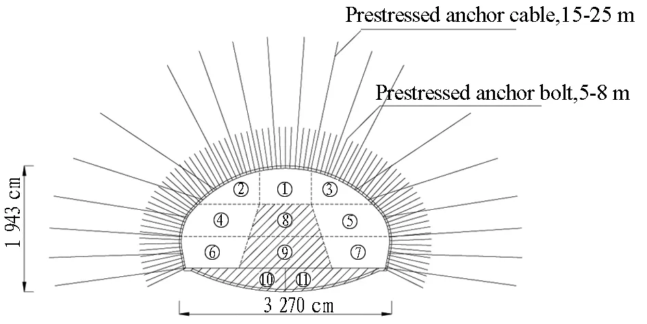
Fig. 4 "Triangle" type excavation method applied to large-span transition section at Badaling Great Wall Station
(2) Safe and reliable structure
In construction, tunnel top (① in the Fig.4) excavation should be performed first to verify the geological conditions in advance and take necessary reinforcement measures accordingly. Next, excavation in layers and steps (②, ③, ④, ⑤, ⑥, and ⑦ in the Fig.4) should be performed according to the principle of "reserving the core, excavating from top to bottom and from two sides to the middle". Finally, the core and inverted arch should be excavated step by step to form a closed support system (⑧, ⑨, ⑩ andin the Fig.4). If this method is used, then the support system should be composed of the pre-grouting small ducts or pipe umbrellas, grid steel frames, shotcrete, prestressed anchor bolts, or cables. During construction, support should be completed promptly for excavation of each part to ensure the construction safety.
(3) High level of mechanization
For each step, the tunnel excavation width is 8-12 m and the height is 5-6 m, allowing for the use of large mechanical equipment.
(4) High construction efficiency
The key to the work involves the excavation and construction of anchor bolts/cables. Multiple sets of equipment can operate at the same time during excavation on a large section, thereby significantly increasing the construction efficiency.
The essence of the "triangle" type excavation method for an ultra-large section is summarized as follows: (1) anchor bolts/cables must be set in place according to the design requirement; (2) prestressed anchor bolts/cables must be able to reach the quick tension. In general, tensioning will be performed within 1-3 days after grouting, and they should reach the design tension at that time.
5 Deformation control
Deformation control is the key for safe construction. In view of the large excavation span and section of the tunnel, the total deformation and the deformation arising in each step were controlled at the same time to perform dynamic management of safe construction.
5.1 Criteria for total deformation control
The currentTechnicalCodeforMonitoringMeasurementofRailwayTunnel(Q/CR 9218-2015) is applicable to single-track tunnels with a span of less than 7 m, double-track tunnels with a span of 7 m to 12 m, and loess tunnels with a span of 12 m to 16 m. The tunnel has an excavation span of 32.7 m, much larger than the scope specified by the current technical code. Therefore, it is necessary to conduct a special study and establish thecriteria for its total deformation control.
5.1.1 Ultimate strain of rock mass
According to the rockmass mechanics and the Hoek-Brown strength empirical formula, the ultimate train of rockmass should be calculated using the following formulas[13]:
(7)
(8)
Em=(0.023 1RQD-1.32)·Er
(9)
whereεmcis the ultimate strain of rockmass,σmcis the compressive strength of rockmass (MPa),Emis the elastic modulus of rockmass (MPa),σrcis the compressive strength of rock block (MPa),σ3is the minimum principal stress (MPa), i.e., the confining pressure borne by the rockmass,mb, s and a are empirical factors reflecting the rockmass characteristics, RQD is the indictor of rockmass integrity, andEris the elastic modulus of the rock (MPa).
5.1.2 Critical deformation of rockmass
The critical deformation of rockmass based on the ultimate strain of rockmass and was obtained it was used as the value for the total deformation control.

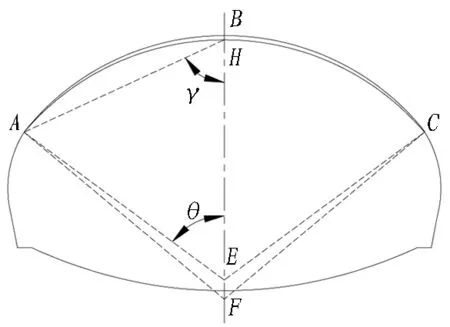
Fig. 5 Calculation model of rockmass critical deformation of tunnel arch crown

(10)
According to the rock mechanical parameters measured on site, the ultimate strain and criticaldeformation of the rockmass were calculated using the formula above. To simplify the site management, the criteria was established for total deformation control of the large-span transition section of the Badaling Tunnel based on two classes: 19.3 m to 25.0 m and 25.0 m to 32.7 m. See Table 5.
5.2 Criteria for Deformation Control in Steps
In view of the large excavation span and section of the tunnel, it is necessary to conduct deformation control in each of the construction steps to ensure safety; otherwise, the structure may become unstable after the deformation exceeds the limit with increase of the span and section. The deformation in each step of excavation was calculated based on numerical simulation; the results are shown in Fig. 6.
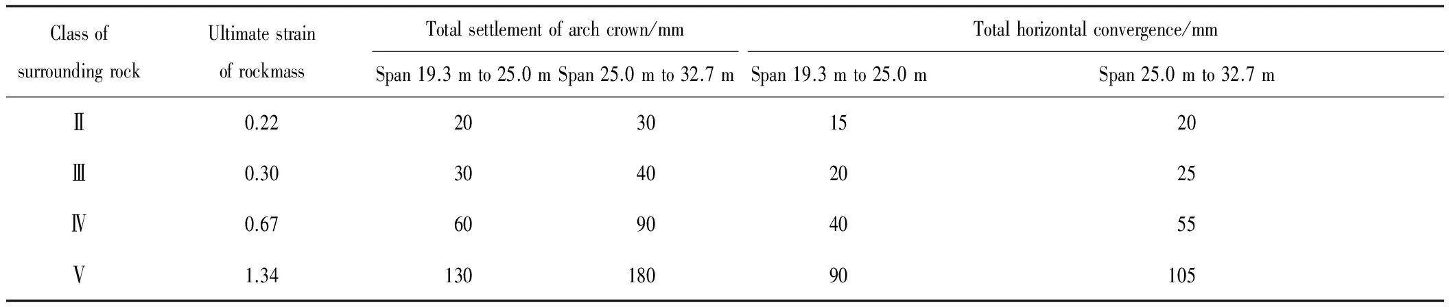
Table 5 Criteria for total deformation control of large-span transition section at Badaling Great Wall Station
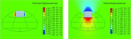
(a) 1st step of excavation

(b) 2nd step of excavation
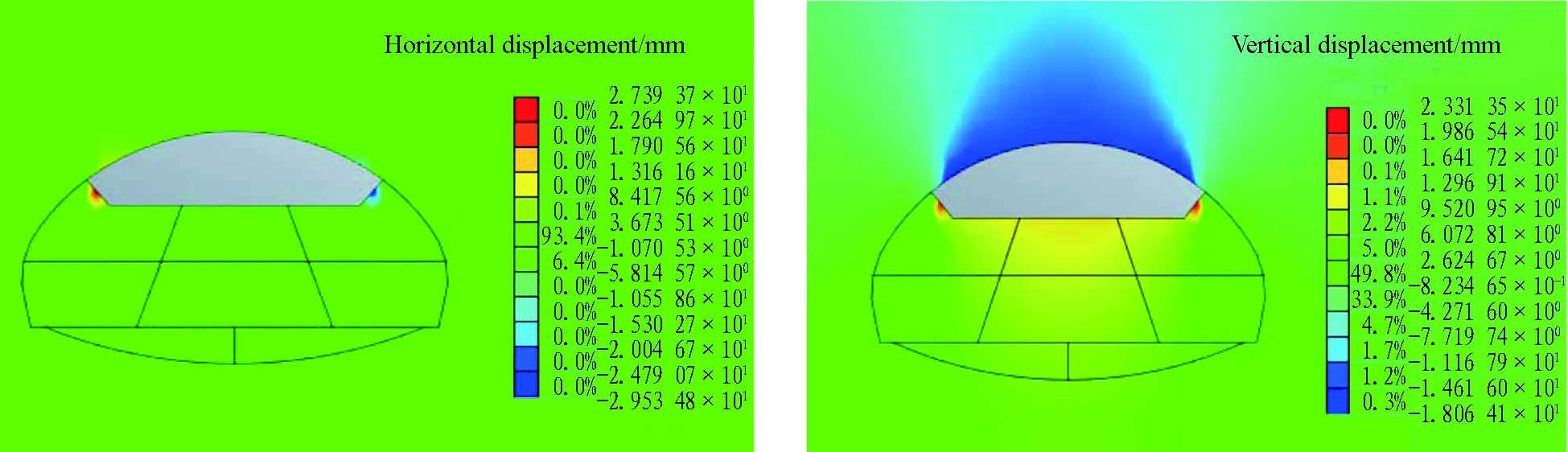
(c) 3rd step of excavation
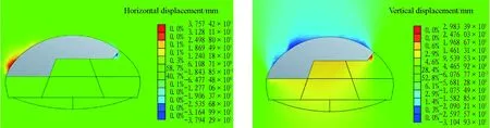
(d) 4th step of excavation
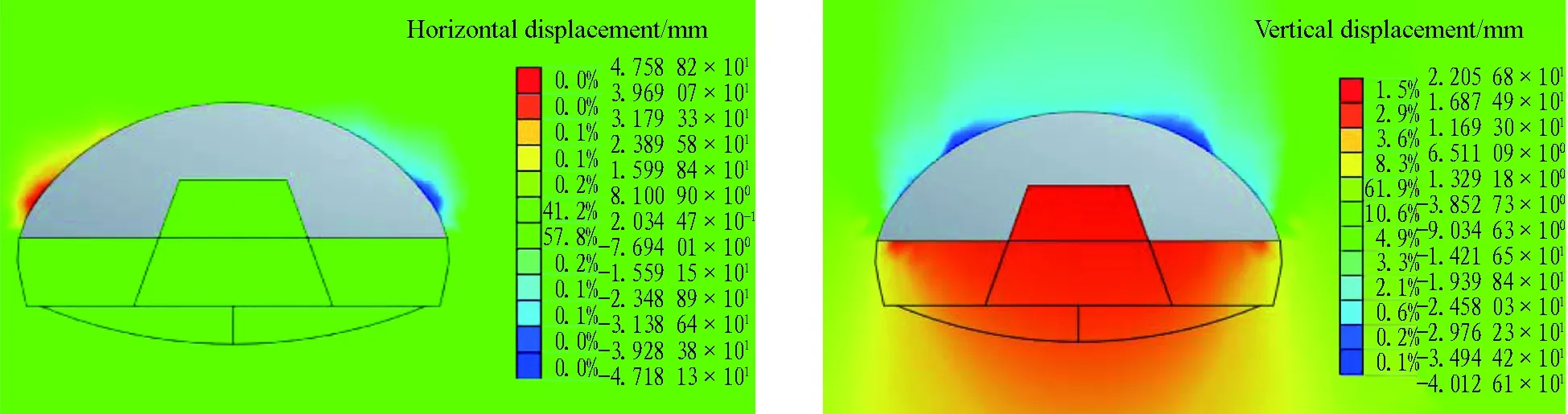
(e) 5th step of excavation
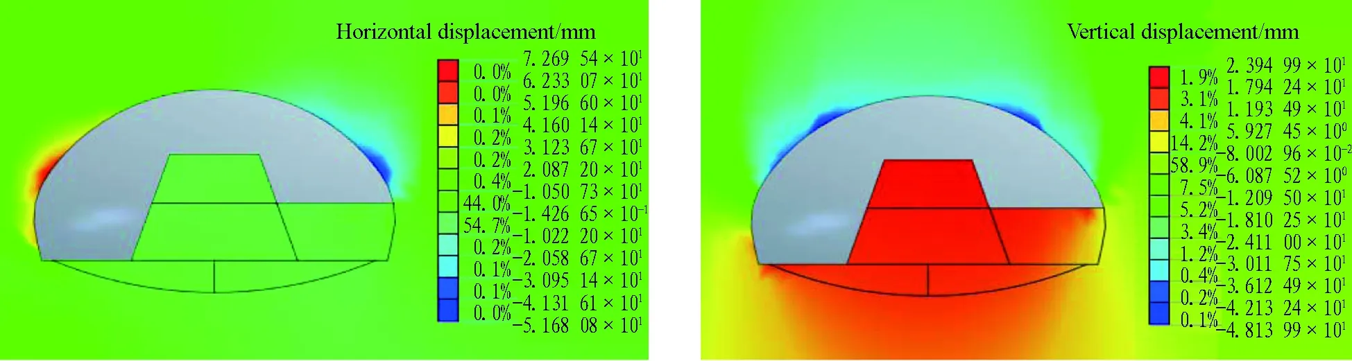
(f) 6th step of excavation
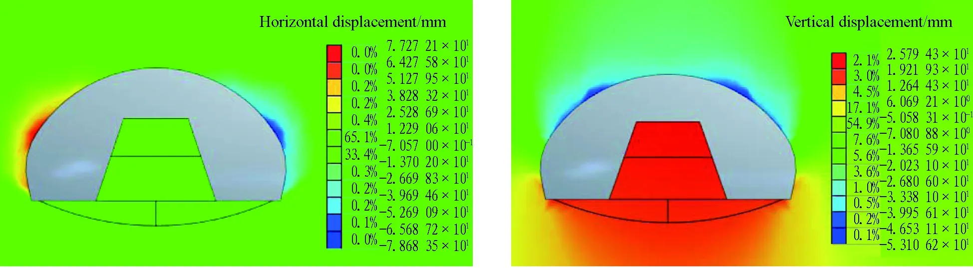
(g) 7th step of excavation
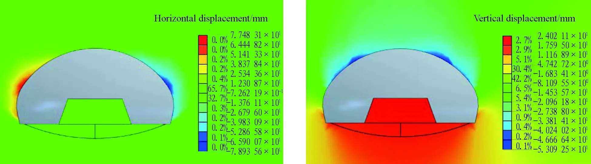
(h) 8th step of excavation
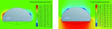
(i) 9th step of excavation

(j) 10th step of excavation
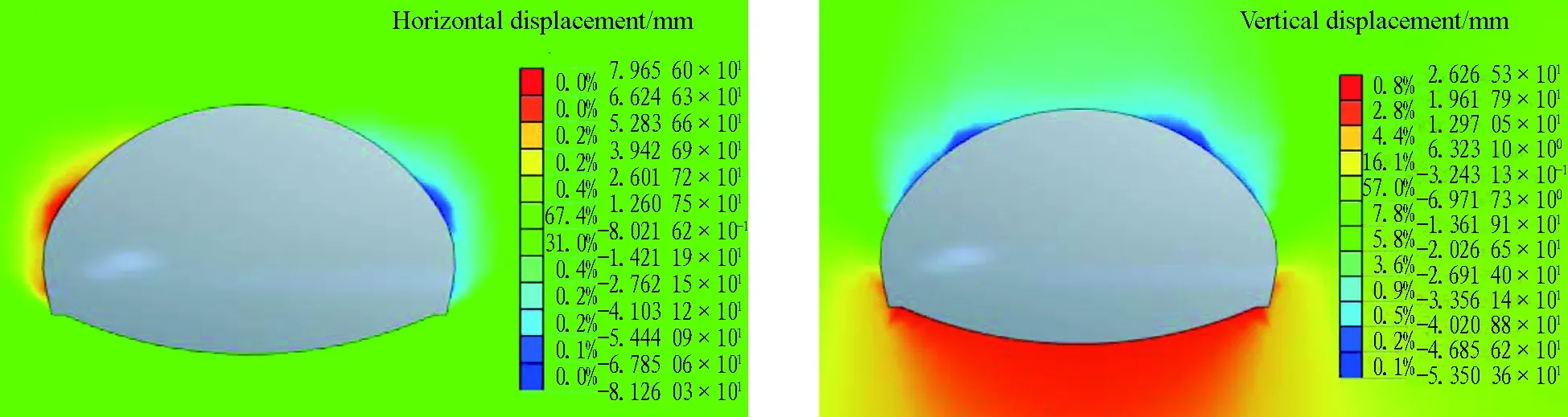
(k) 11th step of excavation
According to the numerical simulation results, the percentage of the deformation in each step was calculated (see Fig. 7); the calculated percentage of each step was used as the criterion for deformation control in the step.
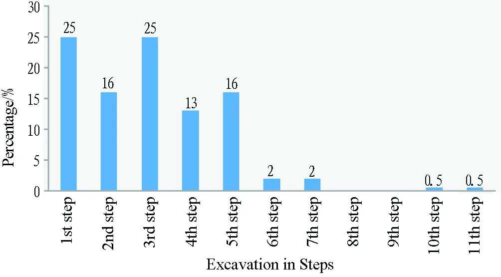
Fig. 7 Percentages of deformation in each step of "Triangle" type excavation
Fig. 7 shows that the deformation mainly arises in the tunnel-arch making stage (1st-5th steps), accounting for approximately 95% of the total, followed by that arising in the side-making stage (6th and 7th steps), accounting for 4% of the total, followed by the smallest deformation only accounting for 1% in the inverted arch-making stage (10th and 11th steps).
5.3 Management of Deformation Control in Levels
According to theTechnicalCodeforMonitoringMeasurementofRailwayTunnel(Q/CR 9218-2015), management in levels was performed based on the deformation in steps, the total deformation and the deformation rate, as shown in Table 6.
6 Conclusions and Experience
(1) According to the checking calculation, our support system for the large-span transition section at Badaling Great Wall Station has a safety factor of 1.16-2.46 during the construction period and 1.59-3.54 during the operation period, i.e., its engineering structure is safe and reliable.
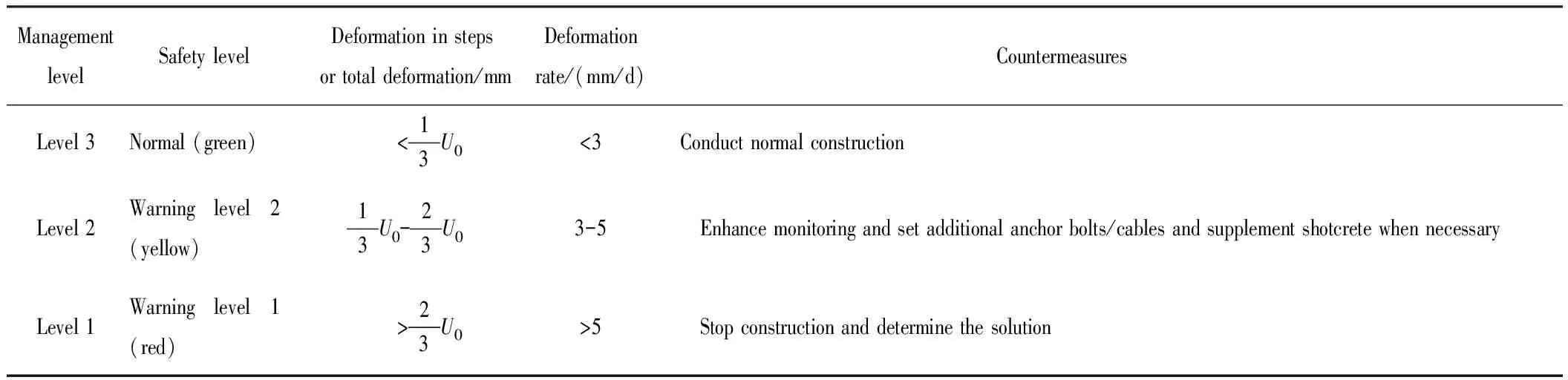
Table 6 Management of deformation control in levels
Remark:U0is the ultimate deformation, i.e., the control value of deformation in each step or the total deformation.
(2)The innovative triangle-type excavation applied to the tunnel with an ultra-large span of 32.7 m and section of 494.4 m2has advantages such as simple and clear methodology, safe and reliable structure, high applicability of machinery and high construction efficiency; thus, it can be popularized.
(3)Based on the ultimate strain, criteria for total deformation control of the large-span transition section at Badaling Great Wall Station were calculated. Depending on different surrounding rock classes and spans, in the case of class Ⅱ surrounding rock, the total settlement is 20-30 mm and total horizontal convergence is 15-20 mm; in the case of class Ⅲ surrounding rock, the total settlement is 30-40 mm and the total horizontal convergence is 20-25 mm; in the case of class Ⅳ surrounding rock, the total settlement is 60-90 mm and the total horizontal convergence is 40-55 mm; in the case of class Ⅴ surrounding rock, the total settlement is 130-190 mm and the total horizontal convergence is 90-105 mm. These values were used as the basis for the deformation control management on site.
(4)According to the numerical simulation, the innovative method of triangle-type excavation results in deformation that is mainly centralized in the tunnel arch-making stage, accounting for approximately 95% of the total, followed by that in the side-making stage, accounting for 4% of the total, with the smallest deformation only accounting for 1% in the inverted arch-making stage. These values were used as the basis for the deformation control management on site.
(5)The deformation measured during the on-site monitoring of the works is much less than the result of the theoretical calculation; this difference demands a further study upon completion of the works.
Acknowledgement
The study was supported by Technological Research and Development Project of China Railway Corporation (2017G007-A).
:
[1] Ministry of Railways of the People′s Republic of China.Technical guide of construction of high-speed railway tunnel engineering[S]. Beijing: China Railway Publishing House, 2011.
[2] Technical code for railway tunnel in loess: Q/CR 9511-2014[S].Beijing: China Railway Publishing House, 2014.
[3] Technical specification for monitoring measurement of railway tunnel: Q/CR 9218-2015[S].Beijing: China Railway Publishing House, 2015.
[4] GUAN Baoshu, ZHAO Yong. Construction technology of soft rock tunnel[M]. Beijing: China Communications Press, 2011.
[5] ZENG Wei,ZHANG Minqing. Analyses of causes for the de-formation intrusion structure ambit of tunnel on Yichang-Wanzhou Railway and its treatment[J]. Journal of Railway Engineering Society, 2008(3): 42.
[6] SONG Ye, WANG Xindong, WANG Gang, et al.Technology for monitoring construction of large section loess tunnel of passenger dedicated line[J]. Journal of Railway Engineering Society, 2010(1): 52.
[7] LI Liping, LI Shucai, ZHAO Yong, et al. 3D geomechanical model for progressive failure progress of weak broken surrounding rock in super large section tunnel[J]. Chinese Journal of Rock Mechanics and Engineering, 2012, 31(3): 550.
[8] WANG Zhijie, XU Ruining, HE Nengfang. Study of deformation characteristics of large coss-section tunnel in Xigeda Fm Strata[J]. Tunnel Construction, 2016, 36(12): 1412.
[9] JIANG Shuping, HUANG Lunhai, HU Xuebing. Design and study of highway tunnel with super-large cross section[J]. Chinese Journal of Underground Space and Engineering, 2005, 1(1): 54.
[10] GAO Jianguo.Design and construction of large section shallow loess tunnel[J]. Communication Standardization, 2011(11): 141.
[11] TENG Fei. Large cross section of soft and plastic clay ground in cold region shallow-buried tunnel construction scheme[J]. Northern Communications, 2011(6): 143.
[12] ZHANG Quanquan. Study of the deformation characteristics and construction parameter optimization of shallow buried tunnel surrounding rock [D]. Kunming: Kunming University of Science and Technology, 2015.
[13] LIU Yourong, TANG Huiming. Rock mass mechanics[M]. Beijing: Chemical Industry Press, 2009.
猜你喜歡
遼寧教育(2022年19期)2022-11-18 07:20:42
公民與法治(2022年5期)2022-07-29 00:47:28
汽車實(shí)用技術(shù)(2022年9期)2022-05-20 05:51:26
教學(xué)考試(高考物理)(2021年5期)2021-11-08 10:31:22
歷史教學(xué)問題(2021年4期)2021-11-05 07:02:34
中醫(yī)眼耳鼻喉雜志(2021年1期)2021-07-22 07:38:14
裝備制造技術(shù)(2020年11期)2021-01-26 00:39:12
中國(guó)公共安全(2017年11期)2017-02-06 05:28:08
電測(cè)與儀表(2016年7期)2016-04-12 00:22:18
燕山大學(xué)學(xué)報(bào)(2015年4期)2015-12-25 02:19:49

- 隧道建設(shè)(中英文)的其它文章
- Statistics of Railway Tunnels in China as of 2017
- 高速鐵路隧道支護(hù)參數(shù)的計(jì)算研究
- 2018年世界隧道大會(huì)暨國(guó)際隧協(xié)(ITA)第44屆年會(huì)將在迪拜舉辦
- Chinese Longest Sea-crossing Metro Tunnel:Wuyuan Bay Station-Liuwudian Station Section of Xiamen Metro Line #3
- Extra-large Undersea Shield Tunnel in Composite Ground:Maliuzhou Traffic Tunnel in Zhuhai
- Construction Technologies for Tunnels in Special and Complicated Geology of Lanzhou-Chongqing Railway