Experimental research on steady-state operation characteristics of gas–solid flow in a 15.5 m dual circulating fluidized bed system
2021-06-26 10:02:48YangjunWeiLemingChengErdongWuLiyaoLi
Yangjun Wei,Leming Cheng,Erdong Wu,Liyao Li
State Key Laboratory of Clean Energy Utilization,Zhejiang University,Hangzhou,Zhejiang 310027,China
Keywords:Chemical looping Dual CFB Steady-state operation Hydrodynamics
ABSTRACT Gas-solid hydrodynamic steady-state operation is the operating basis in a chemical looping dual-reactor system.This study reported the experimental results on the steady-state operation characteristics of gas–solid flow in a 15.5 m high dual circulating fluidized bed(CFB)cold test system.The effects of superficial gas velocity,static bed material height and solid returning modes on the steady-state operation characteristics between the two CFBs were investigated.Results suggest that the solid distributions in the dual CFB test system was mainly determined by the superficial gas velocity and larger solid inventory may help to improve the solid distributions.Besides,cross-returning mode coupled with self-returning is good for steady-state running in the dual-reactor test system.
1.Introduction
Chemical looping technology (CLT) has developed quickly over the recent 2–3 decades [1].It is recognized as a dual-reactor technology.This technology is based on the process where oxygen carriers (MexOy-1) carry oxygen from the air and deposit it as lattice oxygen (MexOy) in one reactor.Then,these carriers flow into another reactor to consume fuel,accomplishing redox reactions between two reactors [2].Therefore,it is significantly essential to accomplish the mass and heat balance in the dual-reactor system.
The two reactors of CLT demand to be matched in mass flow with each other to achieve balanced operation.The types of the reactor include circulating fluidized bed (CFB),bubbling fluidized bed (BFB),spout fluidized bed and moving bed (MB),according to the chemical looping units from 0.5 kWth to 3 MWth [3].The characterization of pressure distribution around a dual fluidized bed system [4,5] could be more complex than a single fluidized bed [6–8].Operating experiences suggest that a combination of two different fluidized beds owns distinctive gas–solid steadystate operation characteristics and operating mechanisms.
The imbalanced operation happened in the dual-reactor system.Many dual fluidized beds(DFB)units for chemical looping required operating adjustment before steady operations [9–16].To study the operating performance of a DFB,gas–solid hydrodynamics of the cold test models are valuable and will aid the optimal design for the hot system.Results of a 120 kWth scaling-down DFB cold test system at Technical University of Vienna showed the solid concentrations in the fuel reactor (FR) and air reactor (AR) were imbalanced when the operating parameters varied[17].In a hydrodynamically scaled 10 kWth Ca-looing (CaL) DFB cold model,all pressure drop terms exhibited sinusoidal fluctuations when the riser was operated at the velocity above the maximum stable operating region [13].Besides,superficial gas velocity was found to be critical to dampening the impact of the slug and fluctuation of the 100 kWth chemical-looping combustor.And the solid circulating rate was largely subject to fluidization velocity [18].Therefore,operating parameters including superficial gas velocity,solid inventory,particle size,particle density,aeration of solid returning system,as well as reactor geometric parameters are essential to systemic balance and gas–solid steady-state operation.
Due to the advantages of gas–solid mixing and high reaction rate,dual circulating fluidized beds (DCFB) system has developed in large scale chemical looping system recently [14,19,20].Literature shows pilot-scaled units were incapable of long-term autothermal operation with high carbon capture efficiency [1,9,21].It indicates it is elementary to understand the method to operate steadily and the steady-state operation characteristics for a DCFB system.
In this study,a 15.5 m dual CFB cold test system was constructed to study its gas–solid steady-state operation characteristics.The effects of important parameters,including superficial gas velocity in each reactor,static bed material height and solid returning modes on steady-state operation were investigated.
2.Experiment
The schematic diagram of the 15.5 m dual CFB test system is shown in Fig.1.It includes a gasifier with I.D.280 mm and a regenerator with I.D.300 mm.Both the gasifier and regenerator are circulating fluidized bed,associated with a cyclone,standpipe and solid returning system.The height above the air distributor of both fluidized beds H is 15.5 m.They are made of plexiglass.The test system was fully surrounded by grounded copper wires to prevent the effect of static electricity.
As shown in Fig.1,the solid is fluidized within the gasifier (2),regenerator(11)and then enters the cyclone(3),(12),respectively.The solid separated by the cyclone passes the main standpipe (4),(13) and is collected in the solid distributing chamber (5),(14).There are two solid returning modes from the distributing chamber to the gasifier and regenerator,which are named as self-returning mode and cross-returning mode,respectively.During solid exchange process between gasifier and regenerator,the crossreturning mode is applied,i.e.(6b)-(7b)-(18) and (15c)-(16c)-(9)paths.The self-returning mode is given as (6a)-(7a)-(8) and(15d)-(16d)-(17) paths.
The pressures in the system were measured along the circulating loops by 50 calibrated pressure transducers.The solid circulation flux Gswas determined by the solid accumulating velocity of a cut off valve in the standpipe.The stop period was limited in a certain range to minimize its error.The air flows of the primary air and solid returning systems were measured by airfoil flowmeters and rotor flowmeters,respectively.

Fig.1.Schematic of the dual CFB test unit.
Quartz sand (>99% SiO2) with a mean sizeof 168 μm was used as the bed material.Its density and bulk density are 2417.34 kg﹒m-3and 1506.43 kg﹒m-3,respectively.The terminal velocity (ut) is 1.15 m﹒s-1and the minimum fluidization velocity(umf) is 0.05 m﹒s-1.
During the tests,the pressures inside of the reactors were set below atmospheric pressure,which is similar to that as a CFB furnace.Test conditions are given in Table 1.It was considered as a steady-state condition when the mass flows are balanced between two CFBs.It was determined as the pressures along the system kept steadily for more than 30 min,and then the data were collected.

Table 1 Test conditions
In Fig.1,the ΔPGa(or ΔPRe)is the pressure drop of the main bed between A and B(or F and G).It can be determined by Eq.(1),manifesting the solid mass in the furnace [22].

where W is the mass of solid in the main bed and A is the crosssectional area of the corresponding CFB.The solid inventory in each reactor at steady condition is characterized by f,as given in Eq.(2),in whichpresents the bulk solid fraction and Hstis the static bed material height.

A ratio of solid inventory I,as given in Eq.(3),is utilized to describe the discrepancy with respect to solid inventory distributions between two reactors at steady-state operation.When I is about 1.0,it suggests that the solid inventory in two reactors are similar.When I is higher than 1.0,it manifests that more solid is fluidized in the gasifier,and vice versa.In this case,the solid distributions between gasifier and regenerator are uneven.

The effects of superficial gas velocity,static bed material height and solid returning modes on pressure distributions,solid inventory distributions I and solid suspension density are studied,describing the gas–solid hydrodynamic steady-state characteristics of the dual CFB system.
3.Results and Discussion
3.1.The effects of superficial gas velocity on gas–solid hydrodynamic steady-state operation
Superficial gas velocity is one of the key parameters influencing the gas–solid hydrodynamic steady-state operation.Tests of operating with similar and different superficial gas velocities in both reactors were carried out.They were operated in cross-returning mode.Experimental results are given from Figs.2–5.Fig.2 and Fig.3 present the pressure distributions and solid suspension density profiles when both reactors were run at similar superficial gas velocity,while those at different velocity are shown in Fig.4 and Fig.5.
Fig.2 shows the pressure distributions profile at similar superficial gas velocities.The fluidization numbers varied from 30 to 40.The differences between two superficial gas velocities in the gasifier and regenerator were less than one fluidization number,resulting from the adjustment accuracy of the air flows.It can be seen the pressure curves of the dual CFB system appeared as two similar triangles at gas–solid hydrodynamic steady-state operation.This indicates the pressure of the system was balanced.The pressure of the solid returning systems (E and J in Fig.1) were the highest to maintain solid circulation.The pressure of PAand PFin the dense region increased as the superficial gas velocities decreased,while the pressure at the exit of the furnace B/G,and the cyclone C/H,D/I varied a little.Calculated with the measured pressures,the solid inventory distributions I of two reactors was about 1.0.It means the solid inventory in two reactors was even at similar superficial gas velocities.
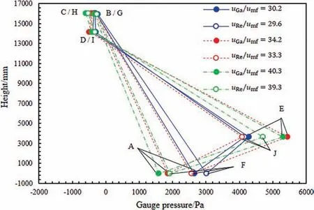
Fig.2.Pressure distributions when both reactors run at similar superficial gas velocities (Hst=350 mm;cross-returning mode;Ga:gasifier;Re:regenerator).

Fig.3.Solid suspension density when both reactors run at similar superficial gas velocities (Hst=350 mm;cross-returning mode;Ga:gasifier;Re:regenerator).

Fig.4.Pressure distributions when both reactors run at different superficial gas velocities (Hst=390 mm;cross-returning mode;Ga:gasifier;Re:regenerator).

Fig.5.Solid suspension density when both reactors run at different superficial gas velocities (Hst=390 mm;cross-returning mode;Ga:gasifier;Re:regenerator).
Fig.3 gives solid suspension density along the reactor height,corresponding to Fig.2.The average solid suspension densities in dense beds were in a range of 300–1500 kg﹒m-3and those in dilute region were within 5–10 kg﹒m-3.As the superficial gas velocity rose,the solid suspension densities decreased in dense regions of both reactors while they increased in the dilute regions.Accordingly,mass and heat transfer of the gas–solid flow would be intensified in the dilute region.However,it may be weakened to some extent in dense regions at higher superficial gas velocity.There are two dense regions at the bottom of two CFBs.Both reactors were at circulating fluidized state.It agreed with the results in Fig.2,where pressure distributions as well as the solid inventory in gasifier and regenerator were similar.
Fig.4 shows the pressure distribution profiles at different superficial gas velocities in the two reactors.The differences between two superficial gas velocities were more than two fluidization numbers.Compared to those at similar fluidization numbers in both reactors (Fig.2),the pressure curves at different superficial gas velocity presented two different triangles when the system was at steady condition.The pressure profiles with higher velocity in regenerator (uRe/umf=36.3,uGa/umf=34.1) are shown by solid lines,while the dash lines present the results with higher velocity in gasifier(uGa/umf=32.3,uRe/umf=30.2).It can be seen the pressure of the dense region in gasifier PAwas higher than that of regenerator PFwhen the fluidization number of regenerator was higher,and vice versa.The solid inventory ratio I was more than 3.5 at uRe/umf=36.3 and uGa/umf=34.1.It was less than 0.5 at uGa/umf=32.3 and uRe/umf=30.2.It suggests that most of the solid was in either gasifier or regenerator while few solid was in the other when solid inventory ratio I was out of 0.5–3.5.The solid inventory distributions between two reactors were uneven at different superficial gas velocity.
Fig.5 gives solid suspension density along the reactor height,corresponding to Fig.4.It can be seen the suspension density profiles of the dense region in one reactor were in a range of 200–25 0 kg﹒m-3,while those in the other reactor were around 5–25 kg﹒m-3when both reactors ran at different superficial gas velocity.When the fluidization numbers were 34.1 in gasifier and 36.3 in regenerator,most of solid inventory was fluidized in the gasifier.This led to a much higher solid suspension density of the dense region in gasifier while the regenerator was almost empty.Similarly,when the gasifier was operated at uGa/umf=32.3 and regenerator at uRe/umf=30.2,few solid was suspended in gasifier while the most solid was fluidized in the regenerator.In this case,the gasifier stayed at pneumatic conveying state.It explained the pressure curves of the dual CFB system showed two different triangles and the solid inventory ratio was out of 0.5–3.5.The system was operated unevenly in this situation.
3.2.The effects of static bed material height on gas–solid hydrodynamic steady-state operation
Fig.6 shows the pressure distributions when the static bed material heights of two reactors Hstwere 350 and 260 mm.Both fluidization numbers in the gasifier and regenerator were about 30 and their differences were less than one fluidization number.As the Hstincreased,more solid was suspended in the reactors and the pressure in the dense region increased.Besides,the pressure curves appeared as two similar triangles at Hst=350 mm,while those were shown differently at Hst=260 mm.Calculated with the measured data,the ratio of solid inventory I at Hst=350 mm was about 1.0 while that at Hst=260 was larger than 1.0.It indicates the solid inventory distributions in two CFBs at higher static bed material height was even.

Fig.6.Pressure distributions when both reactors run at different static bed material heights (solid lines:uGa/umf=30.2 and uRe/umf=29.6;dash lines:uGa/umf=30.6 and uRe/umf=30.2;cross-returning mode;Ga:gasifier;Re:regenerator).

Fig.7.Solid suspension density when both reactors run at different static bed material heights (cross-returning mode;Ga:gasifier;Re:regenerator).
Fig.7 gives solid suspension density along the reactor height,corresponding to Fig.6.The average suspension densities of dense bed in two reactors were in a range of 900–1200 kg﹒m-3and those in dilute region were within 5–10 kg﹒m-3at Hst=350 mm.By contrast,the suspension densities of dense region fell to 100–400 kg﹒m-3when Hstwas 260 mm.And less solid was suspended in dilute region,with average gas–solid density 2–5 kg﹒m-3.There are two dense regions in gasifier and regenerator at both Hst=260 and 350 mm.It means both gasifier and regenerator were at circulating fluidized state.However,the unevenness of solid inventory distributions between two reactors was alleviated as the static bed material height increased.Therefore,a static bed material height at about 350 mm was good to operate the dual CFB system steadily.
3.3.The effects of solid returning modes on gas–solid hydrodynamic steady-state operation
Fig.8 shows the two solid returning modes.Cross-returning mode was showed in Fig.8(a)while cross-returning mode coupled with self-returning was given in Fig.8 (b).Fig.9 shows the pressure profiles operating in different solid returning modes when Hstwas about 395 mm.The difference between two superficial gas velocities in either mode was two fluidization numbers.
In Fig.9,it can be seen the pressure curves of the dual CFB system appeared as two different triangles at different superficial gas velocities when the system was operated in cross-returning mode.It agreed with the results discussed in Fig.4.The solid distributions ratio I was less than 0.5,which means the discrepancy of solid inventory in two reactors was large.By contrast,the pressure difference between the two dense regions,∣PA-PF∣,decreased when the self-returning mode was put into operation.The pressure curves of the dual CFB system was displayed as two different triangles in this mode,but higher pressure of the dense region was in the gasifier where the superficial gas velocity was also higher.It suggests cross-returning mode coupled with self-returning may influence the gas–solid hydrodynamic characteristics of the dual CFB system.The solid distributions ratio I was less than 3.5.The solid inventory distributions were improved to some extent.

Fig.8.Solid returning modes (a) Cross-returning mode;(b) Coupled with selfreturning.
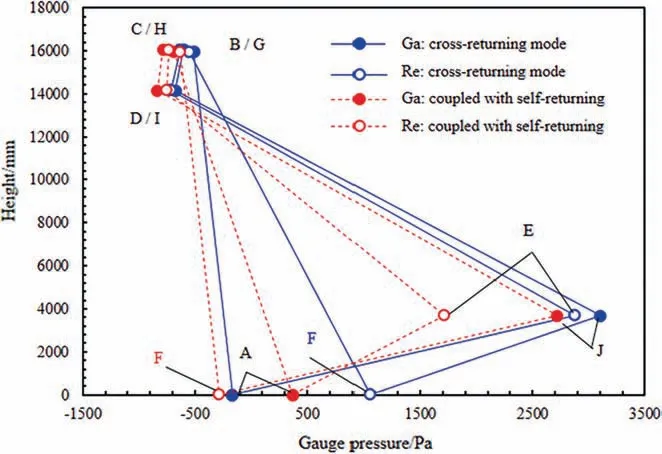
Fig.9.Pressure distributions when both reactors run in different solid returning modes (cross-returning mode:uGa/umf=32.3,uRe/umf=30.2;coupled with selfreturning:uGa/umf=32.2,uRe/umf=30.3;Ga:gasifier;Re:regenerator).
Fig.10 gives solid suspension density along the reactor height,corresponding to Fig.9.It can be seen the difference of solid suspension densities in the dense region between two reactors were large when the system ran in cross-returning mode.The average suspension densities in the dilute region in both reactors were about 2.5 kg﹒m-3.Most solid was fluidized in regenerator while the gasifier was almost empty when the superficial gas velocity in the gasifier was two fluidization numbers higher than that in the regenerator.However,when the system was operated with self-returning as shown in Fig.8 (b),the solid suspension density of the dense region in the gasifier was about 150 kg﹒m-3and that in the regenerator was about 25 kg﹒m-3at uGa/umf=32.2,uRe/umf=30.3.It was different from the results discussed in cross-returning mode.It suggests cross-returning mode coupled with self-returning may affect the solid distributions in two reactors.

Fig.10.Solid suspension density when both reactors run in different solid returning modes.
3.4.Steady-state operation characteristics for the dual CFB test system
The summarized test results of the superficial gas velocity in each reactor,static bed material height and solid returning modes on the ratio of solid inventory distributions in two reactors at steady operation are plotted in Fig.11 (a).An empirical equation was summarized as Eq.(4).It can be seen the ratio I varied exponentially with the

where Hst/H is a dimensionless bed material height.a is 1.41–1.83 and b is 916.9–927.2 for the cross-returning mode,while a=2.11 and b=553.9 for the cross-returning mode coupled with selfreturning.It can conclude that the superficial gas velocity,static bed material height and solid returning modes were important parameters influencing the distributions of the pressure in the system and the solid inventory in two CFBs.Especially,the I was mainly determined by the superficial gas velocity.As showed in Fig.11(a),when I was about 1.0,the pressure curves of the system appeared as two similar triangles and there were two dense regions at the bottom of two CFBs.The solid inventory was distributed evenly and both reactors ran at circulating fluidized state.However,when I was out of 0.5–3.5,i.e.either exponentially large or small,the pressure curves appeared as two different triangles and the solid suspension densities in the dense regions show a large difference.In this case,either gasifier or regenerator was at circulating fluidized state while the other ran at pneumatic conveying state.Fig.11 (b) shows the enlarged picture of the specific region in Fig.11 (a).

Fig.11.The solid inventory distribution I versus operating parameters(Ga:gasifier;Re:regenerator).

Fig.12.Superficial gas velocity regions for steady-state operation of the dualreactor system (Ga:gasifier;Re:regenerator).
Fig.12 gives the relationship between the superficial gas velocities in the two reactors.The experimental data at steady-state operation in Fig.11 (a) were displayed by the empty points.The dual CFB system was able to run steadily at uRe/uGa=0.90–1.05.The solid ones were marked out from the empty ones,representing those at I=0.5–3.5 in Fig.11 (b).And their predictions,according to Eq.(4) and the fitting lines in Fig.11 (b),were showed in the marking regions.It can be seen that the solid points were included in the marking regions.It is noted that the superficial gas velocities in two reactors play a key role in the solid inventory distributions and steady operation.The marking regions represents that both gasifier and regenerator were operated at circulating fluidized state.However,when two superficial gas velocities were set above the marking regions,most solid was fluidized in the gasifier while the regenerator ran at pneumatic conveying state,and vice versa.The fluidization numbers in one reactor were directly proportional to those in the other.
As a conclusion of the steady-state operation characteristics for the dual CFB test system,it is recommended that uRe/uGain a range of 0.90–1.05,the static bed material heights Hst>320–390 mm and self-returning modes can be selected for steady-state running.
4.Conclusions
The effects of superficial gas velocity,static bed material height and solid returning modes on the hydrodynamically steady-state operation characteristics were investigated in a 15.5 m dual CFB test system.The conclusions are concluded as follows:
(1) The superficial gas velocity,static bed material height and solid returning modes are important parameters to run a dual CFB system steadily.In particular,the superficial gas velocity plays a key role in solid distributions in two CFBs.The system was able to run steadily at uRe/uGa=0.90–1.05.
(2) A larger amount of solid inventory is good to improve the solid distributions between two reactors.
(3) The cross-returning mode coupled with self-returning is recommended for steady-state running.
Nomenclature
A CFB cross-sectional area,m2
g acceleration of gravity,m﹒s-2
Gssolid flux,kg﹒m-2﹒s-1
h/H relative height of measured position
H height/longitude of a CFB,m
Hststatic bed height,mm
I solid inventory distributions ratio,%
P gauge pressure,Pa
ΔP pressure drop,Pa
uGasuperficial gas velocity of gasifier,m﹒s-1
umfminimum fluidization velocity,m﹒s-1
uResuperficial gas velocity of regenerator,m﹒s-1
usolidreturningoperating velocity of the solid returning system,m﹒s-1
utterminal velocity,m﹒s-1
W mass of solid,kg
ρssolid density,kg﹒m-3
Subscripts
A or F measured position of gasifier or regenerator in Fig.1
Ga gasifier
Re regenerator
Declaration of Competing Interest
The authors declare that they have no known competing financial interests or personal relationships that could have appeared to influence the work reported in this paper.
Acknowledgements
The authors are grateful for the financial support of National Key Research and Development Program of China(2018YFB0605403).
 Chinese Journal of Chemical Engineering2021年4期
- Chinese Journal of Chemical Engineering的其它文章
- Structure-dependent re-dispersibility of graphene oxide powders prepared by fast spray drying
- Synthesis and optimization of high surface area mesoporous date palm fiber-based nanostructured powder activated carbon for aluminum removal
- Preparation and antibacterial properties of polycaprolactone/quaternized chitosan blends
- Synthesis of zinc oxide nanoparticles reinforced clay and their applications for removal of Pb (II) ions from aqueous media
- Synthesis and characterization of high strength polyimide/silicon nitride nanocomposites with enhanced thermal and hydrophobic properties
- Modeling viscosity of methane,nitrogen,and hydrocarbon gas mixtures at ultra-high pressures and temperatures using group method of data handling and gene expression programming techniques