Numerical simulations of partial elements excitation for hemispherical high-intensity focused ultrasound phased transducer*
2021-07-30 07:43:48YanqiuZhang張艷秋HaoZhang張浩TianyuSun孫天宇TingPan潘婷PeiguoWang王佩國andXiqiJian菅喜岐
Chinese Physics B 2021年7期
Yanqiu Zhang(張艷秋) Hao Zhang(張浩) Tianyu Sun(孫天宇) Ting Pan(潘婷)Peiguo Wang(王佩國) and Xiqi Jian(菅喜岐)
1School of Biomedical Engineering&Technology,Tianjin Medical University,Tianjin 300070,China
2College of Precision Instruments and Optoelectronics Engineering,Tianjin University,Tianjin 300072,China
3Department of Radiotherapy,Cancer Institute and Hospital of Tianjin Medical University,Tianjin 300070,China
Keywords: high-intensity focused ultrasound,partial elements excitation,simulation,phased transducer
1. Introduction
The high-intensity focused ultrasound (HIFU) is a new method developed in recent years for non-invasive ablation of tumors. It can treat deep tumors noninvasively, with little or no damage to the involved tissues,and can be used repeatedly.Currently, HIFU has been used in the clinical treatment of solid soft tissue tumors,such as breast cancer,uterine fibroids,and prostate cancer.[1,2]However,when HIFU treats the transcranial tumor,due to the large difference between the density and sound velocity of the skull and soft tissues, strong attenuation, and absorption of ultrasound, problems such as thermal injury to the skull and insufficient energy in the treatment target area may occur. Early studies of brain HIFU treatment generally used craniotomy to get ultrasound into the brain.[3-5]Ballantineet al. used HIFU to treat the painful subcutaneous neuromata patients, and the results showed that the skull was burned during transcranial treatment and the pain was relieved after partial removal of the skull in 1960.[6]With the development of transducer technology,researchers can use the phased transducers structure and human skull acoustic parameters to perform control to achieve intracranial ultrasound focusing,but too high temperature may cause damage to the skull and surrounding soft tissues.
Recently,in order to address thermal damage to the skull,researchers have investigated hemispherical phased transducer with large diameters that can maximize the area of ultrasound exposure on the skull surface and reduce thermal deposits.Pernotet al. performed numerical simulation and experimental research on the hexagonal,annular,and random distribution of phased transducer array elements to increase the temperature of the therapeutic target area of the transducer,and the results showed that the random distribution of the transducer array elements can be effective by reducing the side lobe,and the focal area can be adjusted in a small range near the geometric focus in 2003.[7]Concoret al. conducted numerical simulation and experimental research on 500 elements phased transducer with an opening diameter of 300 mm, and the results showed that the hemispherical transducer can reduce the ultrasonic energy per unit skull area while focusing on the target area to reduce the risk of skull burns in 2004.[8]McDannoldet al. used the ExAblate 3000 treatment system with a 512-element hemispherical phased transducer with an opening diameter of 300 mm to conduct clinical trials on three glioma patients at a frequency of 0.67 MHz,but none of them developed coagulative necrosis in the target area in 2010.[9]According to Martin’s quote,the fourth patient was treated with a frequency of 0.22 MHz, and the target area tissue was completely ablated,however,the patient died of intracranial hemorrhage five days later.[10]The large-opening hemispheric transducer can be applied to a deeper target area,but its controllable treatment range is small. Hanet al. designed a corona small-opening phase-controlled transducer with a diameter of 100 mm, and the simulation results showed that the random distribution array can significantly reduce the side-lobe sound pressure amplitude and the focus range of the transducer can be extended in 2014.[11]Dinget al. used concentric rings distributed 64-element spherical coronal phased transducers for transcranial focusing and proposed a hot spot reduction method to reduce the temperature rise at the skull in 2015.[12]Qianet al. based on the 82-element phased transducer to screen safe treatment parameters for HIFU transcranial brain tumor treatment, and the simulation results showed that when the input sound power of the transducer element is large,cavitation damage may occur in normal tissues outside the focal zone region in 2018.[13]
This paper is devoted to exciting the coronal part elements in the randomly distributed large-opening hemispherical transducer to expand the range of adjustable focus areas.First,a numerical simulation is performed based on a 176-element phase transducer with an opening diameter of 125 mm, studied the change in the focal area formed by some elements. And then,these results were then applied to a larger computational 256 elements hemispherical phased transducer with an opening diameter of 300 mm for human brain tumor treatment. Finally,we investigate the rules of focus by spherical coronal witch formed in the therapeutic phased transducer to provide technical solutions and methods for HIFU transcranial treatment.
2. Basic equations
In the simulations,the acoustic nonlinear propagation was described by the Westervelt equation[14]
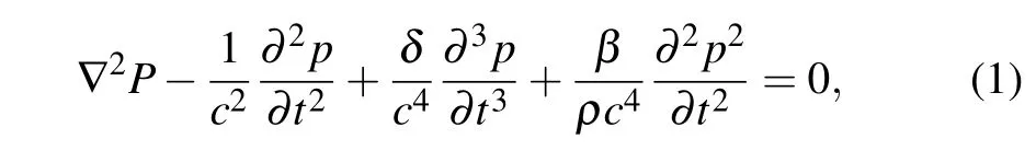
where ?is the Laplace operator,p(in unit Pa) is the acoustic pressure,t(in unit s) is time,ρ(in units kg/m3), andc(in units m/s) are density and sound velocity of the acoustic medium respectively,δis the acoustic diffusion coefficient andδ=2c30α/ω2whereα(in units dB/mm) is the acoustic attenuation coefficient,βis the nonlinear coefficient,ω=2π f(in units rad/s)is the angular frequency,andfis the drive frequency of the transducer.
2.1. Biological heat conduction equation
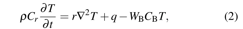
The temperature distribution was calculated through the Pennes’bioheat conduction equation written as[15]
2.2. Thermal dose equation
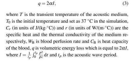
The thermal doset43[16]is defined as
where,Ttis the temperature aftertseconds irradiation,t0andtfinalare the start time and finish time of the irradiation respectively.Ris a constant,ifTt≥43°C,R=0.5 and ifTt <43°C,R=0.25.
3. Simulation model and parameters
3.1. Simulation model
Figure 1 is a simulation model of craniotomy HIFU treatment, including water, brain tissue, and a 125-mm diameter hemispherical transducer. The phased array transducer consisted of 125 elements randomly lied on the hemispherical surface with a 62.5-mm curvature radius and 100-mm diameter.The diameter of each element was 4 mm. The simulation area was a cube with side length of 150 mm. Specifically, the element fill rate was 36%, which is calculated by dividing the total area of the element by the transducer surface.
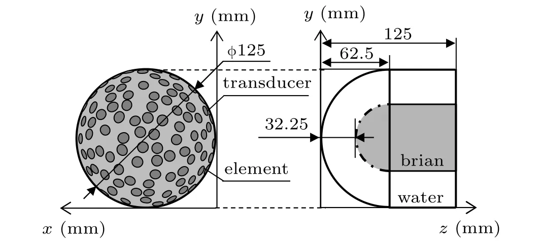
Fig.1. Simulation model of craniotomy HIFU treatment,176-element transducer with 125-mm diameter.
Figure 2 is a simulation model of transcranial HIFU treatment, including water, brain tissue, skull, and a 300-mm diameter hemispherical transducer with a 150-mm curvature radius and 300-mm diameter. The diameter of each element is 8 mm,and the element filling ratio is 36%. In the simulation,a rectangular parallelepiped region with a length and height of 300 mm and a width of 200 mm was calculated, and the parameters such as the structure and shape of the human skull and brain tissues were based on the high-resolution CT of a 49-years old male volunteer’s head provided by Tianjin Medical University Cancer Institute and Hospital. This study is approved by the Ethics Committee of Tianjin Medical University, Tianjin, China, and the written informed consents were obtained from the volunteer. The scan parameters are 120 kV and 135 mA.The slice thickness and spacing are both 3 mm.Simulations were performed with the three-dimensional(3D)FDTD method,in which the spatial step is set to 0.3 mm and the temporal step is 10 ns. The operating frequency of the transducer is 0.7 MHz. Model boundaries are processed using Mur first-order boundary absorption conditions.
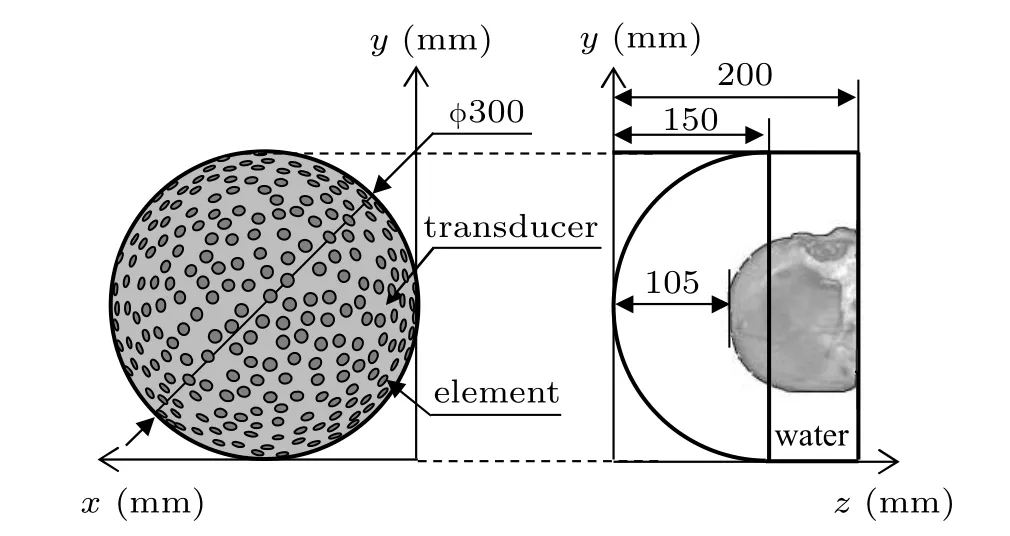
Fig.2. Simulation model of transcranial HIFU treatment,256-element transducer with 300-mm diameter.
3.2. Partial element selection method
3.2.1. Non-circular opening transducer
Figures 3(a)and 3(b)are the places of exciting partial elements that constitute non-circular opening transducer when changing the range of one or two-axis value,where is the area of the selective excitation element. Among them,the colored area is the excitation position.
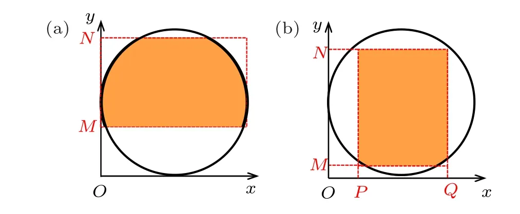
Fig.3. Non-circular opening element excitation position,adjust(a)one coordinate axes from N to M,and(b)two coordinate axes from N to M and P to Q.
3.2.2. Circular opening transducer
Figure 4 is the place of exciting partial elements that constituted a circular opening transducer. The elements around the center ofSclosest to the target pointFwhich was excited.These elements can construct a crown, and the lineSFis the acoustic axis of the partially excited spherical coronal phased transducer.
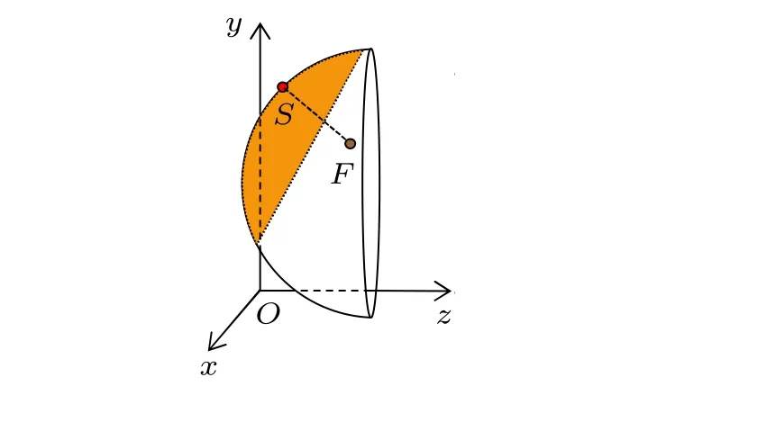
Fig.4. Circular opening elements excitation position.
3.3. Simulation parameters
In this paper, the parameters of the skull and brain tissues such as density (ρ), sound speed (c), attenuation coefficient(α)are obtained from bone porosity(Φ)converted from the Hounsfield unit(H)of the CT images and the calculation method is expressed as follows:[17]
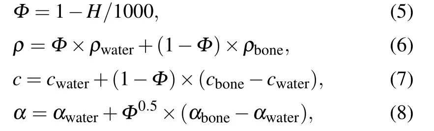
whereρbone,cbone,andαboneare density,speed of sound,and attenuation of cortical skull bone respectively,ρwater,cwater,andαwaterare density,speed of sound,and attenuation of water respectively. Other constant parameters used in the simulation are shown in Table 1.[18]
4. Element driving signal
Figures 5(a) and 5(b) are the processes of driving signal acquisition and focusing. Focus was set as focal targets. An excitation signal that can be focused at focus could be obtained based on the time-reversal method from a point acoustic signalS0(t)=P0sin(2π ft), whereP0is the sound pressure amplitude, andfis ultrasound frequency. By numerical simulation method,the acoustic pressure signalPi(t-Tp)propagating from the sound wave from the point sound source to the elementiwas recorded in sequence. And then,inverting each element according to the time seriesTpat different times to obtain the time inversion signalPi(t) of each element in the transducer. The excitation signal of each array element is produced by Eq.(9).

whereI0is input sound intensity,φiis the phase delay for elementi.
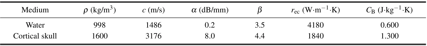
Table 1. Numerical simulation constant parameters.
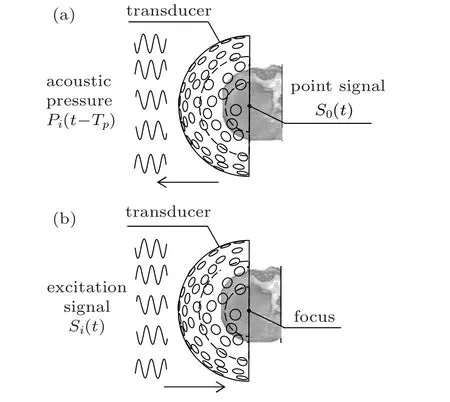
Fig.5. Schematic diagram of(a)acquiring signals and(b)focusing at focus using time inversion.
5. Results
5.1. Hemispherical phase-controlled transducer with 176 elements
5.1.1. Effect of the excitation area ratio
Based on the transducer simulation model shown in 176 elements changing the influence of the ratio of the total area of the selected excitation array to the internal surface area of the transducer(excitation area ratio)from 18%to 36%(entire excitation)to focus with different powers, and the ultrasound propagation time is 3 s. The focus area above 54°C,[19]maximum temperature, maximum sound pressure, and the focus position onzaxis(acoustic axis)are shown in Table 2. From Table 2, the transducer can focus on the target position when the excitation area ratio is 23%(112 elements)or more. And with the increase of the excitation power,the focal area above 54°C and the maximum temperature and maximum sound pressure gradually increase. So we defined the excitation area ratio as 23% which can be accurately focused on the fewest elements and set the power to 50 W in the following study.
5.1.2. Effect of the position of the partial element
Based on Fig.3,112 elements(the excitation area ratio is 23%) at different locations were excited to focus, and the result is shown in Fig.6. Figures 6(a1)-6(f1)are the positions of the exciting element whose outer margin are within the boundary line and closest to array center position, which is the red part. Figures 6(a2)-6(f2)are the focus temperature fields,and figures 6(a3)-6(f3) are the temperature curves of the acoustic axis. From Fig.6,the elements with a 23%excitation area ratio at different positions were focused to form a focus region having almost the same shape. The partial excitation focus area above 54°C is (4.4±0.7) mm2, and the highest temperature is(73±1)°C,which is lower than 81.9°C at entire excitation.
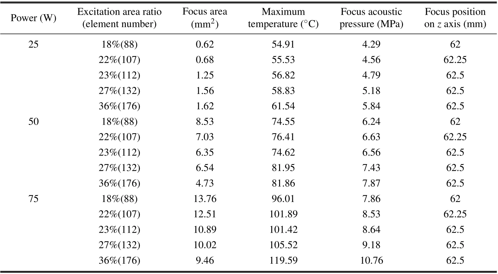
Table 2. 176-element transducer focus results#.
5.2. Hemispherical phase-controlled transducer with 256 elements
Based on the simulation model of the transducer as shown in Fig. 2, the input power is set to 100 W, the stimulus time is set to 20 s for focusing, and the focusing results of 176-element small-opening transducers are used to study this part of focus law.
5.2.1. Effect of the excitation area ratio
Changing the excitation area ratio from 18%to 36%(entire excitation) just like 176-element transducer to focus, the results are shown in Table 3. From Table 3,the transducer can focus accurately when the excitation area ratio is 23%. But when the excitation area ratio is 18%or 22%,the focus position moves forward to a different degree.
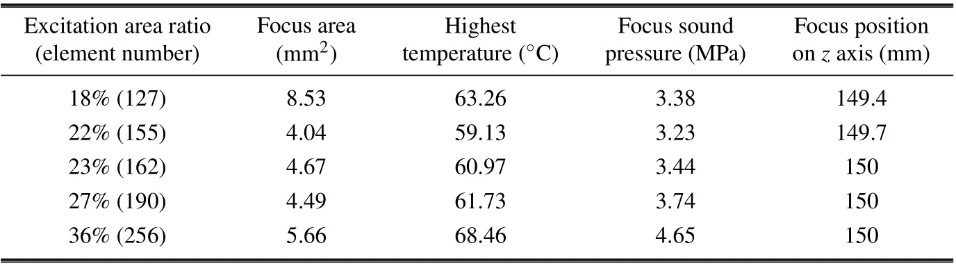
Table 3. 256-element transducer focus results#.
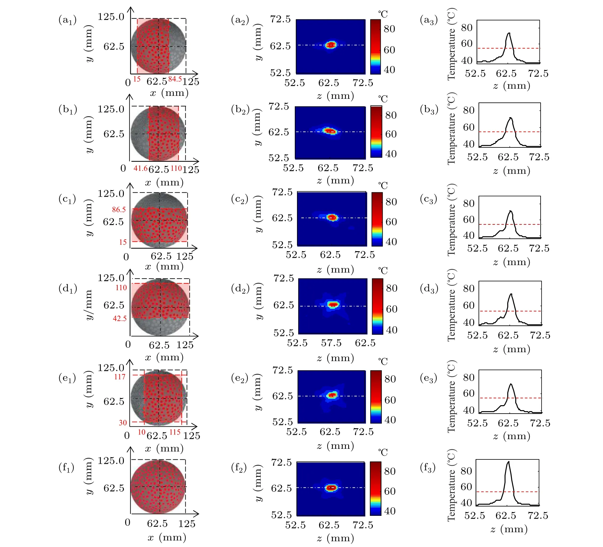
Fig. 6. Focus temperature fields with the 176-element transducer partial excitation, panels (a1)-(f1) are the exciting element areas, panels(a2)-(f2)are the temperature fields,and panels(a3)-(f3)are the acoustic axis temperature curves(P=50 W and t=3 s).
5.2.2. Partial element excitation
Based on Fig.3,162 elements with excitation area ratio is 23%at different locations were excited to focus in a geometric center,and the result is shown in Fig.7.
From Fig.7,the elements with a 23%excitation area ratio at different positions are focused to form a focus region having almost the same shape. The highest temperature at the skull is(38.86±0.04)°C,the partial excitation focus area above 54°C is(3.32±1.3)mm2,and the highest temperature is(58.5±1.86)°C,which is lower than 68.46°C at entire excitation.
5.2.2.1. Focus along the coordinate axis
Based on Fig. 4, 162 elements with the excitation area ratio is 23%at different locations were excited to focus along the coordinate axis at 6-mm intervals. Figures 8 and 9 are the temperature field of thezyplane and its axial temperature curve formed by focusing on thezaxis andyaxis,where the red and black dashed boxes respectively show the results of partial excitation and entire excitation focusing. The left column is the position of the excited elements, the middle two columns are the temperature field,the right column is the temperature curve of control axis, the white curves are the skull outline, the white dotted straight lines are the control axes, and the parts above 54°C are selected as the treatable focal range. From Fig.8,on thezaxis,the maximum control range of partial excitation is from 138 mm to 168 mm, and the maximum control range of the entire excitation is from 150 mm to 168 mm. From Fig.9,on theyaxis,the maximum control range of partial excitation is from 138 mm to 162 mm,and the maximum control range of the entire excitation is from 144 mm to 162 mm. The geometric center of the transducer is(150,150,150).On thezaxis,the adjustable excitation range of the part near the transducer is 12 cm and the entire excitation is almost zero, and away from the transducer, the adjustable range of the partial excitation and entire excitation is the same,both are 18 mm. On theyaxis,partial excitation can increase the entire excitation focus range by 6 mm.
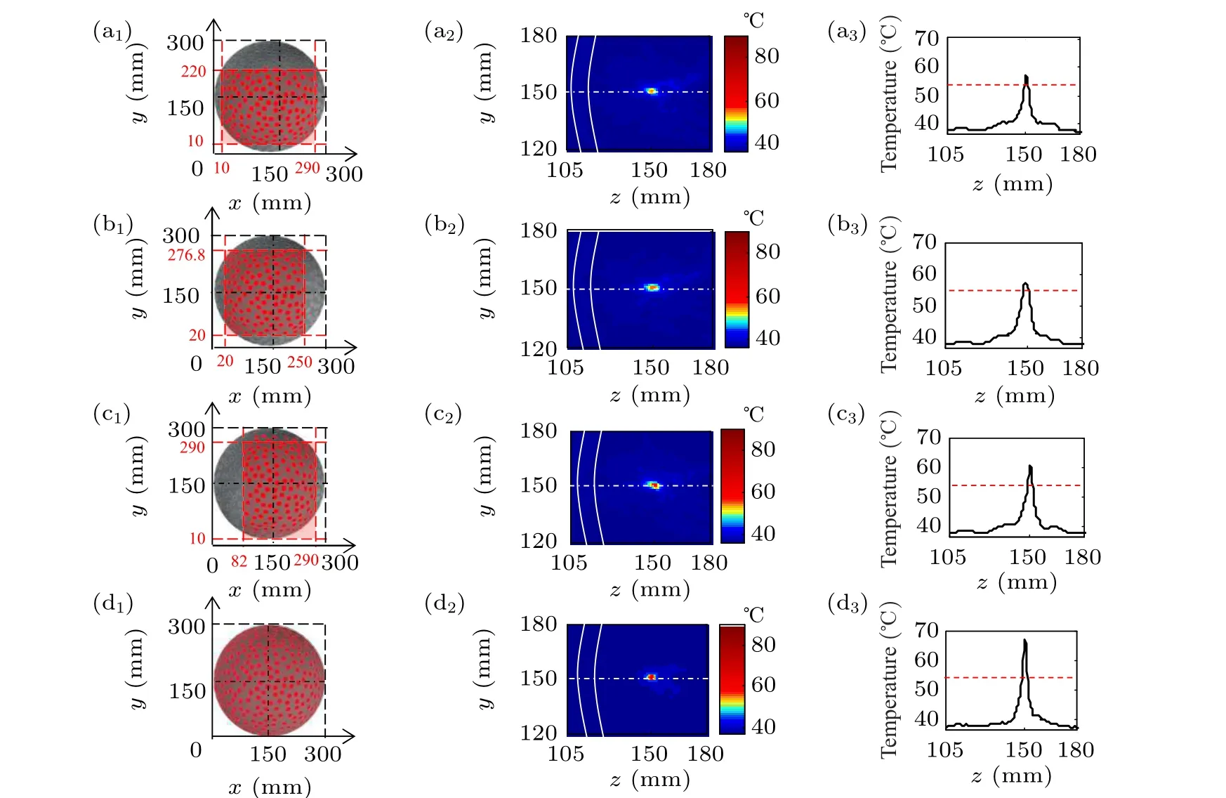
Fig. 7. Focus temperature fields with the 256-element transducer partial excitation, panels (a1)-(f1) are the exciting element areas,panels(a2)-(f2)are the temperature fields,and panels(a3)-(f3)are the acoustic axis temperature curves(P=100 W and t=20 s).
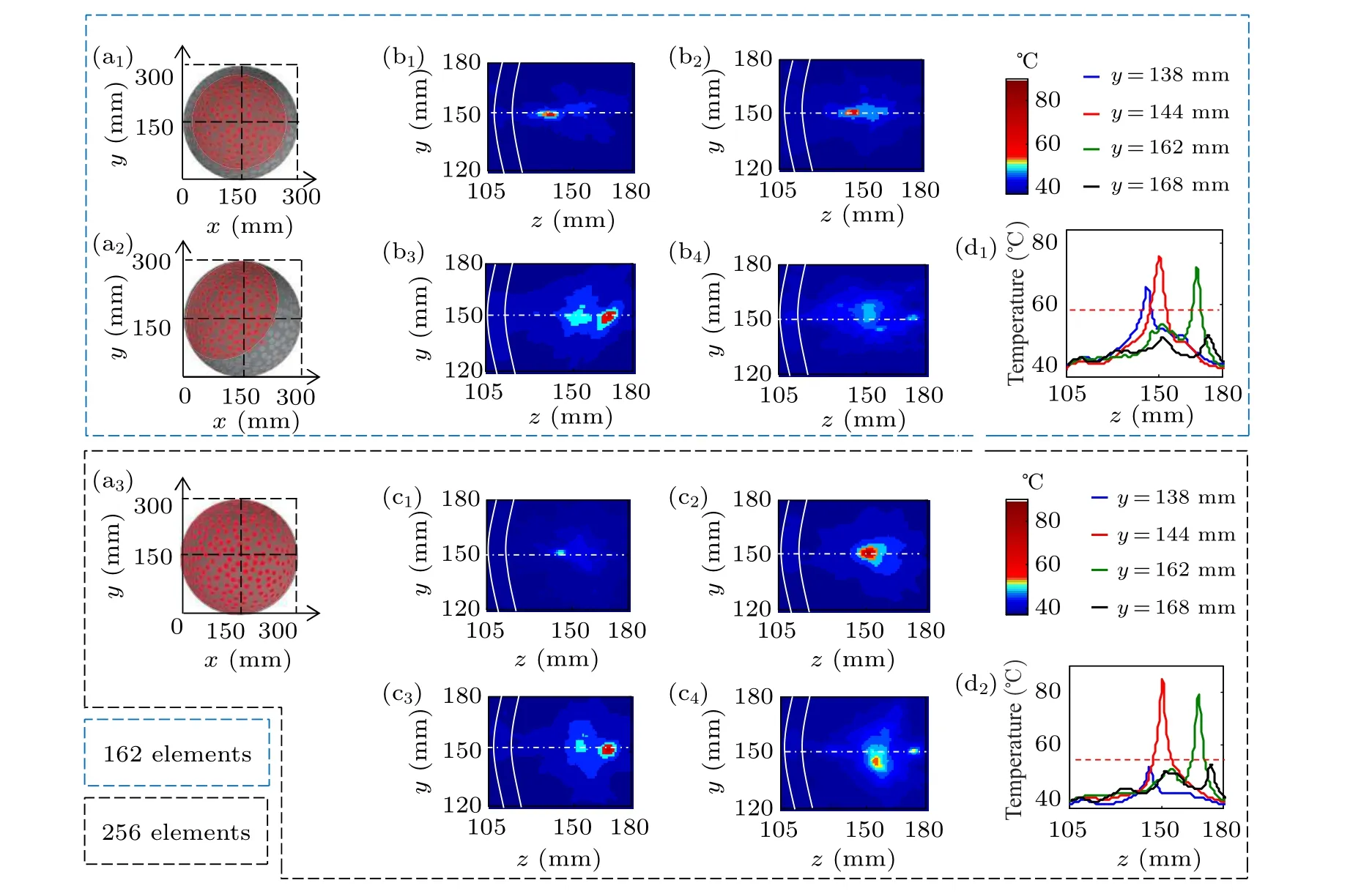
Fig.8.Focus temperature fields under(a1)-(a2)partial or(a3)entire excitation focus on the z axis:panels(b1)-(b4)are the temperature fields at z=138,144,168,174 mm;panels(c1)-(c4)are the temperature fields at z=144,150,168,174 mm; and panels(d1)-(d2)are the temperature curves of the z axis(P=100 W,t=10 s).
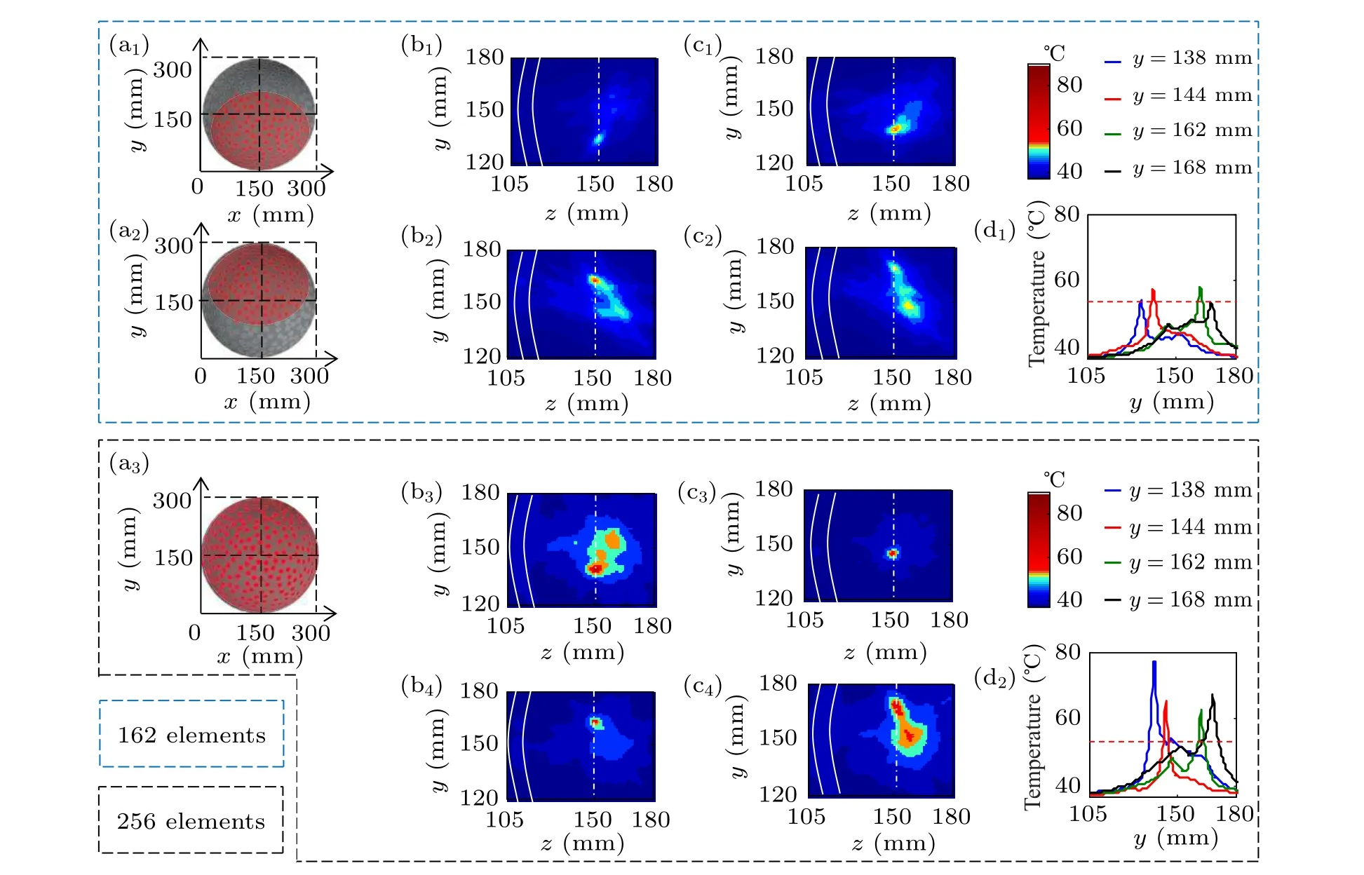
Fig.9.Focus temperature fields under(a1)-(a2)partial or(a3)entire excitation focus on the y axis:panels(b1)-(b4)are the temperature fields at y=132,138,156,162 mm;panels(c1)-(c4)are the temperature fields at y=138,144,162,168 mm;and panels(d1)-(d2)are the temperature curves of the y axis(P=100 W,t=10 s).
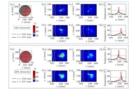
Fig.10. Focus temperature fields with z-y or z-x under(a1)partial and(a2)entire excitation;panels(b1)-(b4)are temperature fields when focus on (156,144,144), panels (c1)-(c4) are temperature fields when focus on (159,141,141); and panels (d1)-(d4) are the corresponding temperature curves in the y direction(P=100 W,t=10 s).
5.2.2.2. Focus of the coordinate axis
Figure 10 shows the temperature distributions when the focal positions were set to(159,141,141)or(156,144,144).From Fig. 10, the temperature of the partial excitation focus region is slightly lower than that of the entire excitation, but the partial excitation focus region is more concentrated, and a non-target secondary focus appears in the entire excitation focus region.
6. Discussion
In this paper,when investigating the focusing range on the vertical acoustic axis of a 256-element large-opening hemispherical phased transducer, only theyaxis focusing results are given (Fig. 9). When the asymmetry of the human skull is not considered, because thex-axis direction and they-axis direction are symmetrical in the numerical simulation model,part of the excitation in thex-axis direction is also larger than the entire excitation. The focus positions (156, 144, 144) in Fig. 10 correspond to points on theOAline in Fig. 11. In Fig.11,Ais symmetrical toA1,B,andB1. Therefore,whenAis(156,144,144),A1is(144,144,144),Bis(156,156,144),andB1is (144,156,144). And the temperature field in Fig. 12 is almost similar to Fig.10. Part of the difference is the effect of skull asymmetry.

Fig.12.Focus temperature fields in point A1(144,144,144),B(156,156,144),and B1(144,156,144)under(a1)-(a3)partial and entire excitation;panels(b1)-(b3)and(c1)-(c3)are the temperature fields at z-y;panels(e1)-(e3)and(f1)-(f3)are the temperature fields at z-x;panels(d1)-(d3)and(g1)-(g3)are the corresponding temperature curves of the z axis(P=100 W,t=10 s).
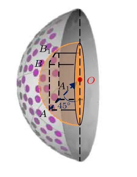
Fig.11. Focus position diagram.
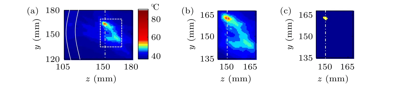
Fig.13. Equivalent thermal dose distribution of partial excitation at(168,150,150),focus temperature field,(b)enlarged view inside the white frame,and panel(c)is the thermal dose(P=100 W,t=10 s).
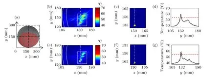
Fig.14. Focus temperature fields under(a)partial excitation at(150,132,150),panel(b)is the temperature fields with P=100 W and t=12 s,panel(e)is the temperature fields with P=200 W and t=5 s,panels(c)-(f)are the enlarged views inside the white frame,and panels(d)-(g)are the temperature curves of the y axis.
It is especially important to ensure the controllability of the focus area. As shown in Fig. 9(b2), when the equivalent thermal dose time is greater than 90 minutes outside the treatable focus area, no thermal damage is formed (Fig. 13). The above analysis and discussion are all based on the focal area of 54°C or more under the same array element excitation power and irradiation time. When the temperature is lower than 54°C, as shown in Fig. 9(b1), an effective focus can be observed by extending the irradiation time (Figs. 14(b) and 14(c))or increasing the input power(Figs.14(d)and 14(e)).
7. Conclusion and perspectives
This paper first takes a numerical simulation model of a small-opening hemispherical transducer with a small amount of numerical simulation calculation as an example. The effects of the focus area, maximum temperature, and focus position of the different numbers of elements are studied to determine the excitation area ratio. Finally,the above results are applied to a hemispherical phase-controlled transducer with a randomly distributed 256-element large-opening,and the temperature fields of the transcranial formations are studied. The specific results are given below.
(i) Array elements with an excitation area ratio of less than 22%move the focus that forms the highest sound pressure forward to the transducer side during excitation,but when excitation area ratio is 23%or more,focus on the target position happens.
(ii)When 23%partial element excitation is used,the controllable range of the treatable focal region formed in the threedimensional space is larger than the full excitation.
This paper proposes that a hemispherical phased transducer with an excitation area ratio of 23% can achieve the same focusing effect at full excitation. This conclusion is similar to Iacopinoet al. who used a 1024-element hemispherical phased transducer with an opening diameter of 300 mm to treat Parkison’s disease and pointed out that at least 700 elements must be stimulated to achieve the predetermined focus effect.[20]
In this paper, only one volunteer’s CT data are used for modeling and numerical simulations. To consider the impact of individual differences revealed by the human body,we will simulate the CT data of heads of more volunteers to build models. Besides, the irradiation conditions will also be discussed to explore their effect on the formation of focal areas.

- Chinese Physics B的其它文章
- Magnetic-resonance image segmentation based on improved variable weight multi-resolution Markov random field in undecimated complex wavelet domain*
- Structure-based simulations complemented by conventional all-atom simulations to provide new insights into the folding dynamics of human telomeric G-quadruplex*
- Dual-wavelength ultraviolet photodetector based on vertical(Al,Ga)N nanowires and graphene*
- Phase-and spin-dependent manipulation of leakage of Majorana mode into double quantum dot*
- Deep-ultraviolet and visible dual-band photodetectors by integrating Chlorin e6 with Ga2O3
- Extended-source broken gate tunnel FET for improving direct current and analog/radio-frequency performance*