Design and Selection of Material for Plastic Gears
2021-09-10 20:34:21NaveenKumarManishKumarSinghAjeetKumar
Naveen Kumar Manish Kumar Singh Ajeet Kumar
Abstract
The use of plastic and polymer composite gears is increasing because of their low cost, lightweight and quiet operation compared to metal gears. Plastic gears find application in printers, cameras, timers, counters, etc. Four different combinations of materials for pinion and gear were selected in the present work, and a comparative study was done to investigate mechanical and thermal properties analytically. Analytical results were validated using SOLIDWORKS and ANSYS. Design 1 and Design 2 were found out to be preferable designs. Maximum principal and maximum shear stress generated were minimum for Design 1 (pinion of Polycarbonate and gear of Acetal copolymer). Simultaneously, the deformation and temperature rise were minimum for Design 2 (pinion of Nylon 66 and gear of Acetal copolymer).
Keywords: ANSYS; Plastic gear; Design; Pinion
1.Introduction
Plastic gears are an excellent alternative to metal gears because of their lightweight, low noise production, low cost, and high corrosion resistance [1] [2]. Historically, plastic gears were used mainly for light-duty applications such as printer, watches, toys, etc., because of their low strength and thermal resistance compared to the metal gears [3] [4]. With the development of stronger and more consistent polymers, plastic gears are also being used for transmitting high power [5]. The most commonly used materials for plastic gears are Acetal Copolymer, Nylon 66, Polycarbonate, Polyester, etc. [5] [6]. Various reinforcements such as glass fibers, natural fibers, carbon nanotubes are also added to the above-mentioned polymer matrices to fabricate composite plastic gears [7] [8] [9] [10]. The properties of plastic gears, such as life and noise production, depend on pinion and gear material [11]. Gears are designed based on the types of failures that occur in the gear while in operation. Gear can fail by mechanical process, environmental and working condition [12]. Fatigue is the main reason for teeth breakage. Each time the tooth is engaged, it is subjected to varying load. Hence alternating bending stresses are developed at the root of the teeth. Various wear mechanisms are adhesive wear, abrasive wear, pitting, plastic flow, etc.
Four different combinations of materials for pinion and gear were selected in the present work, and a comparative study was done to investigate mechanical and thermal properties analytically. Analytical results were validated using SOLIDWORKS and ANSYS.
2.Materials and Method
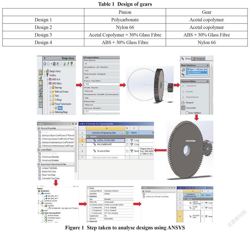
Four different combinations of materials for pinion and gear were selected. Materials used for specific design are given in Table 1. Comparative study of the mechanical and thermal properties of mashing of pinion and gears for all the selected design was done analytically using data available in the literature [5] [13] [14] [15] [16]. Analytical results were verified using ANSYS (R15.0). Steps taken to analyse designs using ANSYS are shown in Figure 1.
3.Symbols and Formulae Used
3.1 Symbols
a = Centre distance between shafts (cm)
i = Gear ratio
Z1 = Number of teeth on pinion
Z2 = Number of teeth on gear
M = Standard module (mm)
d = Pitch circle diameter (mm)
pc = Circular pitch (mm)
b = Face width (cm)
α = Pressure angle
ψ = b/a
ψm= b/m
Mt = Torque transmitted by pinion (Ncm)
Db = Diameter of base circle (mm)
E1 = Youngs modulus of the pinion
E2 = Youngs modulus of the gear
E = Equivalent Youngs modulus
σe = Endurance strength
Ft = Tangential force
d1 = Diameter of pinion
N1 = Speed of pinion (rpm)
Kcl = Life factor
CR = Factor depending on surface hardness
N2 = Speed of gear (rpm)
Kext = Wear factor
φ = Pressure angle
P = Power (kW)
Sc = Surface stress intensity
θ1 = Surface temperature of pinion
θ2 = Surface temperature of gear
θa = Ambient temperature (30℃)
f = Friction factor (0.2-0.25)
U = Transmission ratio (Z2/Z1)
K1, K2 = VDI 2545 factors (2.5)
K3 = Housing factor (0)
A = Surface area of housing
χ1, 2 = Index of material of pinion and gear
3.2 Formulae
Formulae used for the design of plastic gears are given below [13] [14] [15] [16].
3.3 Pre-requisite for Design
Pre-requisite (i.e., physical properties, mechanical properties, and design data) for the design of plastic gears are given in Table 2, Table 3, and Table 4 [13] [14] [15] [16].
Similarly, calculations for other designs were done and the results obtained are given in Table 6. Surface stress intensity and unit load are minimum for Design 2. On increasing the surface stress intensity, wear of tooth increases. On the other hand, on increasing the unit load, the chances of tooth breakage increases. So, according to failure criteria, Design 2 is safer.
Similarly, calculations for other designs were done and the results obtained are given in Table 7. Temperature rise in pinion is minimum for Design 2. At the same time, temperature rise in gear is the minimum for Design 4. The temperature rise in gear for design 2 is also not very high. So, from a thermal failure point of view also, Design 2 is safer.
5.3 ANSYS Results
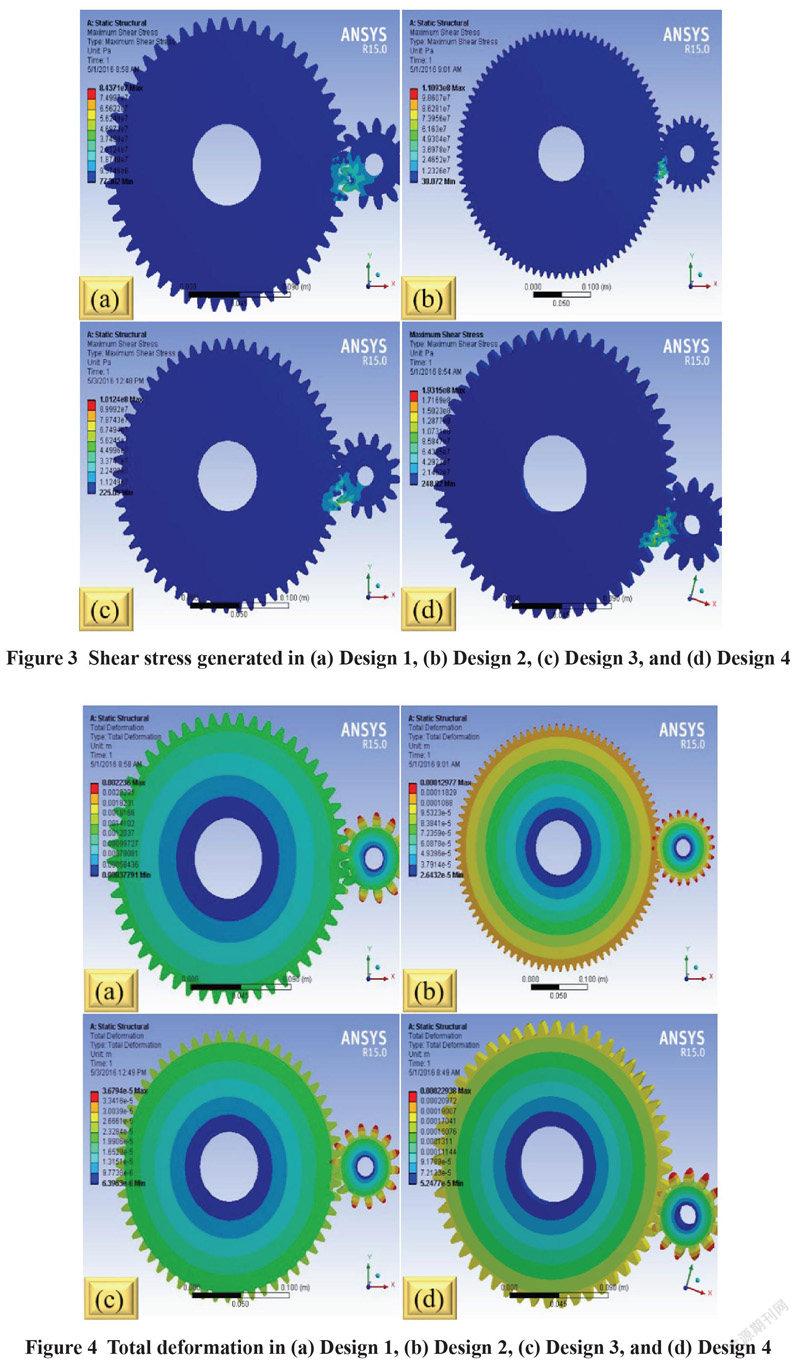
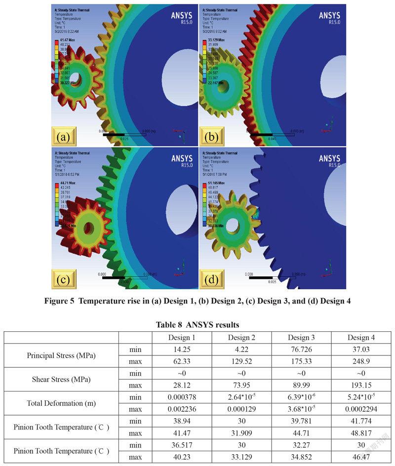
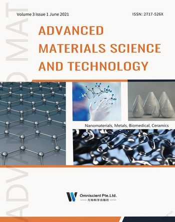
Figure 2, Figure 3, Figure 4, and Figure 5 show maximum principal stress, maximum shear stress, total deformation, and temperature rise in various designs. ANSYS results are given in Table 8.
6.Discussion
The design was performed for gear mesh of polymer or reinforced polymer composite of a combination of Polycarbonate, ABS (+30% glass fibre), Acetal copolymer and Acetal copolymer (+30% glass fibre). All the designs were performed for power transmission of 5 kW @ 300 rpm and ambient condition of 300 C, and atmospheric pressure. Considering the strength of polymer combinations, the pinion and gear specifications were designed. The design specification includes the centre line distance, actual module, diameter of pinion and gear, and the required number of teeth on both wheels for each design.
It can be observed from Table 6 that the surface stress intensity and unit load are minimum for Design 2. On increasing the surface stress intensity, wear of tooth increases. On the other hand, on increasing the unit load, the chances of tooth breakage increases. So, according to the failure criteria, Design 2 is safer. Unit load and surface stress intensity are highest for Design 4, so Design 4 is more prone to failure. According to design according to failure criteria, the best combination of pinion and gear will be Nylon 66 and Acetal copolymer, respectively.
It can be seen from Table 7 that the temperature rise in pinion is also minimum for Design 2. At the same time, temperature rise in gear is minimum for Design 4. Temperature rise in gear for design 2 is also not very high (2.5℃). So, from a thermal failure point of view also, Design 2 is safer.
As per the parameters designed, the designs were analysed on the ANSYS for mechanical and thermal aspects. The maximum principal and maximum shear stress generated in the first design were the least for all designs. So, where the strength of the gear in terms of the stress is required for power transmission of 5 kW @ 300 rpm, then pinion can be made of Polycarbonate and gear of Acetal copolymer. The centre distance and size of the first design were also least, which shall require less space. The deformation of the second design was the least. So, where deformation is the constraint, then pinion can be made of Nylon 66 and gear of Acetal copolymer.
From thermal analysis, the surface temperature generation of the gear and pinion for the second design was the least. If the temperature is the constraint, then the pinion should be made of Nylon 66, and gear should be made of Acetal copolymer.
Suppose the operating temperature of gear is allowed up to 50-60℃. In that case, power transmission required is up to 5 kW @ 300 rpm, then Design 1 is the most feasible and economical design as the size and centre line distance is less; hence space requirement is least among the four designs. The Principal and shear stress generated in the tooth is the least. Design 1 shall be preferred where pinion is made of Polycarbonate and gear is made of Acetal copolymer.
If less heat generation is required, then Design 2 shall be preferred, which has the least total deformation for the same required power transmission of 5 kW @300 rpm. In this case, dimensions are larger than other designs as well centre distance is large, requiring more space than others. In this case, the pinion is made of Nylon 66, and the gear is made of Acetal copolymers.
So, Design 1 and Design 2 are preferable designs.
Conclusions
Following conclusions were drawn after analysing the designs analytically and using ANSYS:
The size and centre line distance were least in the case of Design 1. Hence, when space requirement is a constrain, then pinion can be made of Polycarbonate and gear of Acetal copolymer.
Surface stress intensity and unit load obtained were minimum for Design 2 (pinion of Nylon 66 and gear of Acetal copolymer). The best combination of material for pinion and gear is Nylon 66 and Acetal copolymer, respectively, to prevent tooth breakage and excessive wear.
Temperature rise in pinion was minimum for Design 2 (pinion of Nylon 66), while the temperature rise in gear was minimum for Design 4 (gear of Nylon 66). So, Nylon 66 is the best material for making pinion and gear if only temperature rise is considered.
The maximum principal and maximum shear stress generated in Design 1 were the least. So, where the strength of the gear in terms of the stress is the failure criteria, then pinion can be made of Polycarbonate and gear of Acetal copolymer.
Acknowledgement
Authors are very thankful to Dr. Shailendra Singh, Mechanical Engineering Department, GGU Bilaspur for his valuable guidance. Authors are also thankful to Mr. Abhishek Vatsa, Mechanical Engineering Department, GGU Bilaspur for his continuous support and valuable suggestions.
References
[1] Z. Lu, H. Liu, R. Zhang, C. Zhu, Y. Shen and D. Xin, "The simulation and experiment research on contact fatigue performance of acetal gears," Mechanics of Materials, vol. 154, p. 103719, 2021.
[2] P. K. Singh, K. Mausam and A. Islam, "Achieving better results for increasing strength and life time of gears in industries using various composite materials," Materials Today: Proceedings, 2021.
[3] K. F. Wotodzo, K. A. Kassegne, D. Koffi, S. Tiem and A. Batako, "A numerical simulation of the influence of torque on the performance of composite gears," Materials Today: Proceedings, 2021.
[4] B. H. Soudmand and K. S. Nezhad, "Experimental investigation on the durability and failure modes of polybutylene terephthalate/calcium carbonate nanocomposite gears," Engineering Failure Analysis, vol. 120, p. 105113, 2021.
[5] A. N. Taywade and V. G. Arajpure, "Design and Development of Nylon 66 Plastic Helical Gears in Automobile Application," International Journal of Engineering Research & Technology, vol. 3, no. 9, pp. 1330-1334, 2014.
[6] K. Gupta and S. Chatterjee, "Analysis of Design and Material Selection of a Spur gear pair for Solar Tracking Application," Materials Today: Proceedings, vol. 5, pp. 789-795, 2018.
[7] A. K. Singh, Siddhartha and P. K. Singh, "Polymer spur gears behaviors under different loading conditions: A review," Journal of Engineering Tribology, pp. 1-19, 2017.
[8] S. Senthilvelan and R. Gnanamoorthy, "Wear characteristics of injection-moulded unfilled and glass-filled nylon 6 spur gears," Journalof Engineering Tribology, vol. 2018, pp. 495-502, 2004.
[9] A. K. Singh and Siddhartha, "Thermal and Wear Behavior of Glass Fiber-Filled Functionally Graded Material-Based Polyamide 66 Spur Gears Manufactured by a Novel Technique," Journal of Tribology, vol. 140, pp. 1-16, 2018.
[10] N. Kumar, A. Bharti and M. K. Gupta, "Effect of Treatments on Thermo-mechanical Properties of Epoxy based Sisal Biocomposites," International Journal on Emerging Technologies, vol. 11, no. 3, pp. 491-495, 2020.
[11] B. Cerne, M. Petkovsek, J. Duhovnik and J. Tavcar, "Thermo-mechanical modeling of polymer spur gears with experimental validation using high-speed infrared thermography," Mechanism and Machine Theory, vol. 146, p. 103734, 2020.
[12] A. Yadav, "Different types Failure in gears-A Review," International Journal of Science, Engineering and Technology Research, vol. 1, no. 5, pp. 86-92, 2012.
[13] Design Data (Data Book of Engineers), Coimbatore: Kalaikathir Achchangam.
[14] S. Beermann, "Estimation of lifetime for plastic gears," Kiss Soft, Switzerland, 2007.
[15] R. Walter, "Engineering Principles for Plastic Gears," Gear Solution, 2004.
[16] "Design of Plastic Gears," KHK Stock Gears. [Online]. [Accessed 2 4 2021].
 Advanced Materials Science and Technology2021年6期
- Advanced Materials Science and Technology的其它文章
- Machine Learning for Next-generation Printed Technologies
- A Journey into the Determination of Polyaniline Molecular Weight
- Synthesis, Electrical and Dielectric Properties of Ca-doped SrTiO3 Ceramics
- Nano-structured Ni-based Active Species Supported on Metallic Substrates as the Efficient Catalysts