A simulation study of polarization characteristics of ultrathin CsPbBr3 nanowires with different cross-section shapes and sizes
2023-03-13 09:19:18KangYang楊康HuiqingHu胡回清JiaojiaoWang王嬌嬌LinglingDeng鄧玲玲YunqingLu陸云清andJinWang王瑾
Chinese Physics B 2023年2期
Kang Yang(楊康) Huiqing Hu(胡回清) Jiaojiao Wang(王嬌嬌)Lingling Deng(鄧玲玲) Yunqing Lu(陸云清) and Jin Wang(王瑾)
1School of Telecommunication and Information Engineering,Nanjing University of Posts and Telecommunications,Nanjing 210023,China
2School of Opto-Electronic Engineering,Nanjing University of Posts and Telecommunications,Nanjing 210023,China
Keywords: CsPbBr3,nanowire,polarization characteristics
1.Introduction
All-inorganic metallic halide perovskites such as CsPbX3(X= Cl, Br, I) have attracted great attention due to their superior optical properties,[1,2]e.g., great charge transport properties,[3,4]high quantum yield[5,6]and acceptable stability in comparison to organic perovskites.[7]Thanks to these advantages, nanocrystals (NCs),[8,9]nanorods (NRs)[10,11]and nanowires (NWs) based on this material have been designed and prepared.Among them, CsPbBr3NWs have easy-to-design dimensions and well-defined structural anisotropy.Theoretically, optical devices with a high structural anisotropy exhibit excellent anisotropic photoelectric properties.[12]Therefore, CsPbBr3NWs can also exhibit strong polarization-dependent light emission, absorption, and photoconductivity.[13]In addition, CsPbBr3NW arrays with small lateral dimension (e.g., below 20 nm) and well-aligned structure would be very promising for optoelectronic and display applications due to their significant polarization sensitivity.
In recent years, considerable efforts have been made to fabricate all-inorganic CsPbBr3perovskite NWs.[14,15]The solvothermal method is the most common one used to synthesize 1D perovskite NWs.[16,17]Based on this method,NWs with uniform morphology can be prepared by adjusting the ratio of raw materials and experimental process parameters.However, the defect state and carrier recombination on the surface destroy the stability of NWs.Also, it is still problematic to fabricate perovskite NWs in the form of arrays,which is critical for the practical devices with a large area.These prevent their industrial application.The CVD method has been applied to fabricate the perovskite NW arrays.[15]The so-fabricated perovskite NW arrays showed good polarization characteristics for a cross-section height of 15 nm.However, the perovskite NW arrays still tend to decompose in air.Besides, there have been some realizations of vertical perovskite NW arrays inside anodized aluminum oxide(AAO)templates.[18-20]Using the AAO template can effectively prevent the lateral diffusion of water and oxygen molecules,and thus improve the stability of NWs.However, the geometries of NWs are limited to the pores of AAO template, whose dimension is usually in a range of tens nm and vertical.Thus,it is difficult to fabricate the horizontal and ultrathin perovskite NW arrays.In addition,the AAO cannot bring the photoelectric gain to the prepared NWs.[20]
Recently, a novel strategy has been proposed to synthesize perovskite materials with the help of porous MOFs.[21,22]In this strategy,the ionic compositions of perovskite are firstly encapsulated in the MOF pores;then,the metal sites of MOF can adsorb ionic compositions of perovskite at specific positions and restrict the growth of ionic compositions of perovskite along the pore direction through the steric hindrance effect of the pore; finally, the perovskite quantum dots are synthesized while being confined in the MOF pores.In this way, the MOF pores provide effective surface passivation for perovskite quantum dots,thus reducing the surface defects of the generated perovskite quantum dots.In addition,compared with perovskite materials, MOFs have good chemical, thermal and water stability.[23-25]Thus,such perovskite quantum dot@MOF composites can exhibit not only excellent fluorescence quantum efficiency but also improved stability.[21,22]In fact,such a strategy has been successfully adopted to fabricate other quantum dot@MOF and dye@MOF composites.[26,27]Furthermore,lots of MOFs have highly ordered channels,e.g.,MOF-5, MOF-TED, MOF-74, etc.The ordered channels of these MOFs can orientate the quantum dots, dyes and polymers via the electrostatic adsorption and steric effect,[24,28]when they are encapsulated in the MOF channels.These composites have shown quite impressive polarized luminescence characteristics.[29,30]Therefore, it can be inferred that, if the CsPbBr3NWs are synthesized in the MOF channels,they can exhibit not only the highly polarized luminescence but also the improved stability by mitigating the influence of water and oxygen.In addition, the periodically structure of the MOF channels can further construct the ordered CsPbBr3NW array.However, due to the morphology diversity of the MOF channels, the appropriate structure parameters and morphology of CsPbBr3NWs with good polarization characteristics are not clear.
In this work, ultrathin CsPbBr3NWs with hexagonal,square and triangular cross-section shapes are modelled, and their polarization characteristics are analyzed via the simulation with the finite difference time domain (FDTD) method.Under an excitation light, the normalized intensities of the light coupled into respective NWs are calculated, when the polarization direction of the excitation light is in parallel with or perpendicular to the longitudinal direction of NWs.The polarization ratios of the NWs are calculated by comparing the normalized intensities coupled into the NWs for the excitation light at two orthogonal states of polarization.The polarization characteristics of these morphologically different NWs are compared for the same height or area of cross-section.Also, the influence of the length-height ratio of the NW on its polarization characteristics is analyzed.
2.Structure and simulation
2.1.The structure of CsPbBr3 NW
Because MOFs with different channel shapes such as triangular,[31]square[32]and hexagonal[23]have been reported,the cross-section shapes of CsPbBr3NWs are chosen to be triangular, square and hexagonal for comparison.The structure of the CsPbBr3NW is schematically shown in Fig.1.The height of the cross-section isT,the area of the cross-section isSand the length of the NW isL.The length-height ratio(LHR)is defined as the ratio between the length and height of the NW.The refractive index of CsPbBr3NWs is set as 2.36.[15,33]A polarized continuous wave(CW)light at 405 nm is used as the excitation light.
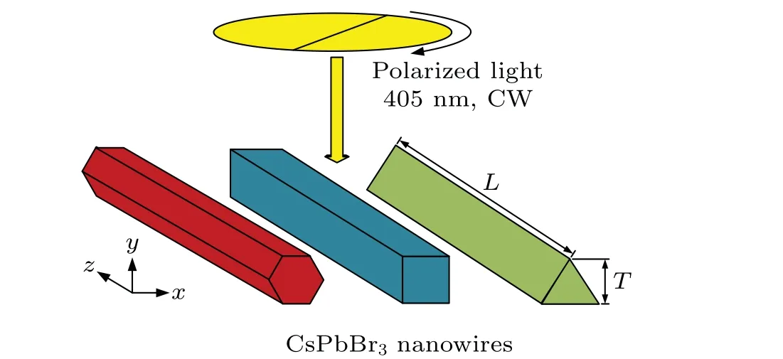
Fig.1.CsPbBr3 NW with triangular, square and hexagonal crosssection shapes, where the height and length of NWs are T and L respectively.The NWS are excited from the top with a polarized CWlight at the wavelength of 405 nm.
2.2.Characterization method
As pointed in Ref.[34], the emission anisotropy of the light out of low-dimensional semiconductor nanostructures is mainly caused by the dielectric confinement of optical electric field in these structures, namely, the dielectric mismatch between high dielectric NWs and surrounding air.In fact,the quantity of the emission light is mostly decided by the quantity of the excitation light coupled into such structures.Therefore,to obtain optimal morphology parameters with better anisotropic photoelectric properties, the anisotropy of the excitation light coupled into ultrathin CsPbBr3NWs with different cross-section shapes and sizes are investigated.
To characterize the anisotropy of the excitation light coupled into the CsPbBr3NWs,the normalized intensity of excitation field coupled into the NWs and the polarization ratio of the NWs are introduced.The normalized intensityIcoupled into the NWs defined on the cross-section plane (x-yplane shown in Fig.1)can be expressed as
whereE0is the electric field distributed on thex-yplane without the NWs,E1is the electric field coupled into the NWs on the same plane, and the integral regionSis the cross-section of CsPbBr3NWs.The polarization ratioρof the NWs can be calculated by comparing the normalized intensities coupled into the NW for the excitation light at two orthogonal states of polarization,[35]
whereI‖andI⊥are the normalized intensities coupled into the NWs when the polarization direction of the excitation light is in parallel with and perpendicular to the longitudinal direction of NWs,respectively.
3.Results and discussion
3.1.CsPbBr3 NWs with same height
The electric field distribution on the cross-section plane are firstly simulated for the CsPbBr3NWs with different crosssection shapes but a same heightT=10 nm,shown in Fig.2,
where the angleθbetween the polarization direction of the excitation light and the longitudinal direction of NWs is 0°(E0°,upper panel)or 90°(E90°,bottom panel),respectively.It should be noticed that the minimal height of 2 nm is chosen in view of the reported value of 2.2 nm for CsPbBr3NWs.[14]It can be seen that the excitation fields coupled into the NWs are lower than the incident excitation fields, especially when the polarization direction of the excitation light is perpendicular to the longitudinal direction of NWs (θ=90°).The difference between the electric fields inside and outside the NWs is small for all of three different cross-section shapes when the polarization direction of the incident excitation light is in parallel with the longitudinal direction of NWs(θ=0°),as shown in Fig.2(a).In comparison,forθ=90°shown in Fig.2(b),the electric field is very different inside and outside the NWs,and only a little excitation light is coupled into the NWs for all three cases.
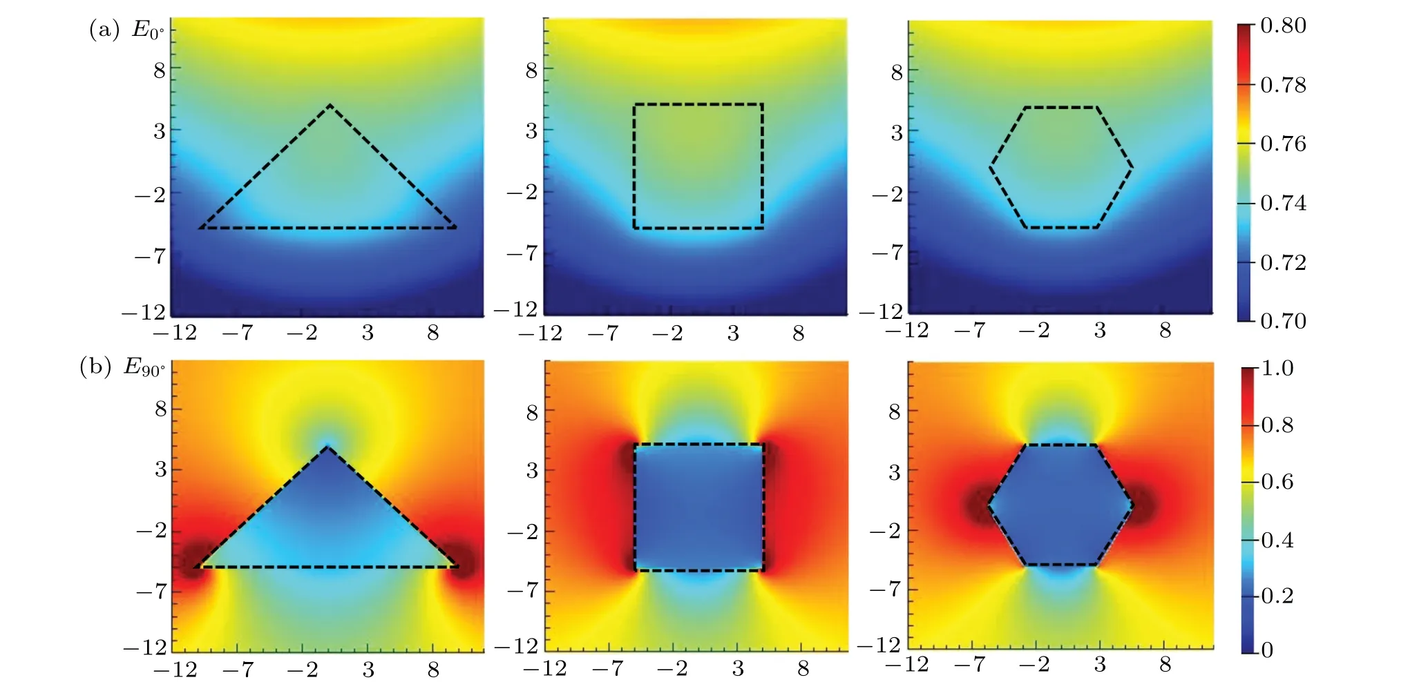
Fig.2.(a) and (b) The electric field distributions on the cross-section plane of CsPbBr3 NWs with the triangular, square and hexagonal cross-section,when the angle θ between the polarization direction of the excitation light and the longitudinal direction of NWs are 0° and 90°.
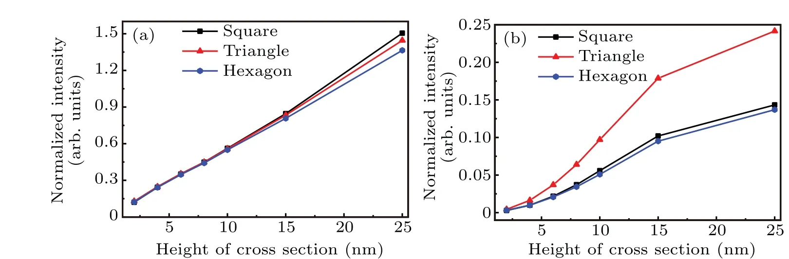
Fig.3.Normalized intensities on three cross-sections versus the height of NWs.Panels(a)and(b)are the cases of the polarization direction of the excitation light is in parallel with and perpendicular to the longitudinal direction of NWs.
The coupling efficiency of an excitation light into NWs can be quantitatively expressed with the normalized intensity.Figure 3 shows the normalized intensities coupled into the NWs versus the height of cross-section of the CsPbBr3NWs with different cross-section shapes.It can be seen that for three different NWs the normalized intensities atθ=0°are higher than those atθ=90°.It can also be seen that for two polarization directions of the excitation light,the normalized intensities on three cross-sections of the NWs increase with the increase of the heightT.This is because the cross-section area of NW increases with the increase of the heightT,and more excitation light is coupled into the NW accordingly.Forθ=0°,the coupling efficiency namely the normalized intensities on three cross-sections of the NWs are almost same at smaller height values and show a little difference at larger height values,as shown in Fig.3(a).On the other hand,the coupling efficiency is obvious different in the case ofθ=90°.As shown in Fig.3(b), the normalized intensities increase rapidly whenT<15 nm,and increase slowly whenT>15 nm.Especially,the normalized intensity on the triangular cross-section is the highest among these three cases atθ=90°.It is because the electric field at the bottom of the triangular cross-section is stronger than those of other two cases, as shown in Fig.2(b).In fact,it can be seen that the NW with triangular cross-section has a lower structural anisotropy.Concretely,the bottom edge of the triangular cross-section is longer and narrower than that of other two cross-sections, and the electric field of thex-yplane in the former case is less affected by the dielectric confinement effect.Thus, more excitation light can be coupled inside the bottom of the triangular cross-section.
Figure 4 depicts the polarization ratio of CsPbBr3NWs with different cross-section shapes versus the height of crosssection.It can be seen that along with the increase of the height the polarization ratios of these three NWs decrease untilT=15 nm, and increase afterwards.The reason for that is the much faster increase of the normalized intensities forθ=90°with the increase of the heightTuntil 15 nm,as shown in Fig.3(b), while the normalized intensities increase slowly afterT= 15 nm.Among these three cross-section shapes,the NWs with the square and hexagonal cross-section shapes have higher polarization ratios than the triangular one.This is mainly due to the fact that the normalized intensity on the triangular cross-section is relative higher than those on other two cross-sections whenθ=90°,while the normalized intensities on three cross-sections are almost large whenθ=0°.In addition, the NW with the hexagonal cross-section has a little higher polarization ratio.It might be attributed to the little smaller area of the hexagonal cross-section with the same height.In addition,when the heightT=15 nm and 25 nm,the experimentally measured polarization ratios of the CsPbBr3NWs with the triangular cross-section from Ref.[15] are depicted as the dashed ranges in Fig.4.It should be noticed that the measured polarization ratios are larger than the simulated values of the triangular NW, but smaller than the simulated values of the square or hexagonal NW.This would reflect the truth that the cross-section of the NW prepared experimentally was not an ideal triangle,and more or less tended to square or hexagon.Therefore, the comparison with the experiment results validates the simulation results of this work.
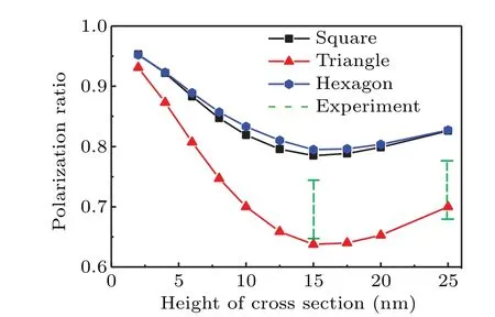
Fig.4.Polarization ratio of CsPbBr3 NWs for different heights of the cross-section, where the length-height ratio is 20:1.At the height of 15 nm and 25 nm,the dashed ranges scale out the experimentally measured polarization ratios of CsPbBr3 NWs with the triangular crosssection from Ref.[15].
3.2.CsPbBr3 NWs with same area
To further investigate the polarization characteristics between the NWs with different cross-section shapes, the normalized intensities on the cross-section plane and the corresponding polarization ratios of these NWs with the same cross-section areaSare compared,as shown in Fig.5.It can be seen that for two polarization directions of the excitation light,the normalized intensities on three cross-sections of the NWs increase with the increase of the cross-section areaS.Also,up to a cross-section areaS=100 nm2, the polarization ratios of these three NWs increase with the decrease of the area.Again, forθ=90°shown in Fig.5(b), the normalized intensity, namely, the coupling efficiency on the triangular crosssection is larger than those on other two cross-sections with the same cross-section area, while forθ=0°shown in Fig.5(a)the normalized intensities on these three cross-sections with the same cross-section area are almost large.This leads to the result that the polarization ratio of the NW with the triangular cross-section is lower than those of other two cases,as shown in Fig.5(c).Another detail in Fig.5(c)is that the polarization ratio of the NW with the hexagonal cross-section is in general larger than those of other two cases.
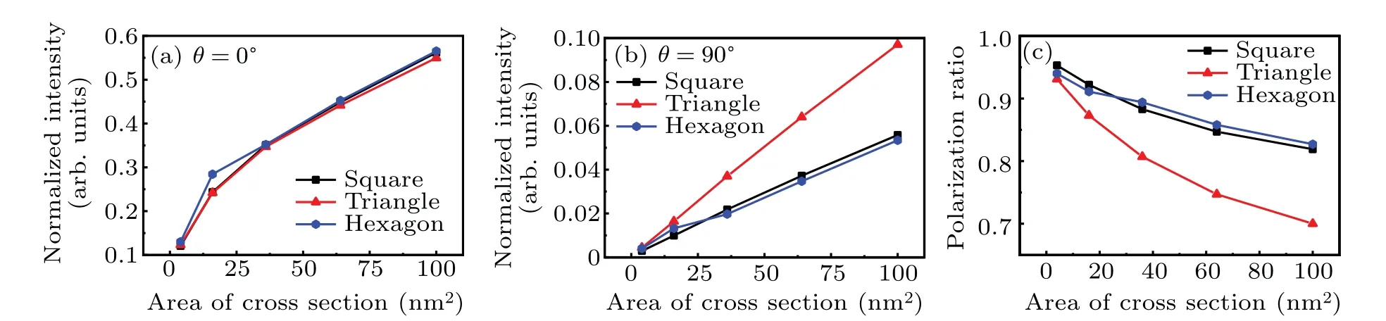
Fig.5.Normalized intensities on three cross-sections versus the cross-section area of NWs.Panels(a)and(b)are the cases of the polarization direction of the excitation light is in parallel with and perpendicular to the longitudinal direction of NWs.(c) Polarization ratio of CsPbBr3 NWs for different cross-section areas.The length-height ratio is 20:1.
3.3.Hexagonal NWs with different length-height ratio
In this section, the normalized intensities on the crosssection plane and the corresponding polarization ratio of the hexagonal NW for different length-height ratios (LHRs) are calculated and shown in Fig.6, where the height of crosssection is 10 nm.It should be noticed that the normalized intensities are calculated for the cross-section at the central point(z=0)of NW.It can be seen that forθ=0°,the normalized intensity of the cross-section increases with the increase of LHR until LHR=30:1,then decreases afterwards.Forθ=90°,the normalized intensity of the cross-section decreases with the increase of LHR until LHR=45:1,then increases afterwards.These variations lead to a maximal polarization ratio of the hexagonal NW when LHR=45:1.

Fig.6.Normalized intensities coupled on the cross-section at the central point(z=0)of the hexagonal NW for different length-height ratios(LHR), and the corresponding polarization ratio, where the height of cross-section is 10 nm.
To understand the variation of the normalized intensities and the polarization ratio, the distributions of the electric field along the longitudinal direction of the NW with different LHRs are shown in Fig.7.It should be noticed that the longitudinal section plane is thex-zplane in the middle height of the NW.It can be clearly seen that the electric fields along thex-axis are different for different LHRs.It is due to the interference construction along the longitudinal direction inside the NWs,which is mainly induced by the reflection of the electric field at the end facets of NWs.At the end facets,theExcomponent is continuous and theEzcomponent is discontinuous due the dielectric difference between the CsPbX3material and the air.Forθ=0°, the amplitude ofEzcomponent is much larger than that ofExcomponent.Therefore,considerable reflections occur at both end facets, resulting in a considerable interference along the longitudinal direction of NW.In particular,when the LHR of NW is 30:1,the constructive interference occurs atz=0, resulting in a maximal electric field and normalized intensity on the cross-section.In addition, it can be seen that when the LHR of NW is 60:1,the constructive interferences occur atz=±200 nm.In comparison, forθ=90°,Exis the main component of the electric field,but is weak due to the weak coupling.Therefore, although there are certain reflections on both end facets,the interference construction in the NW is weak,where the electric field reaches the minimum when the LHR=45:1.
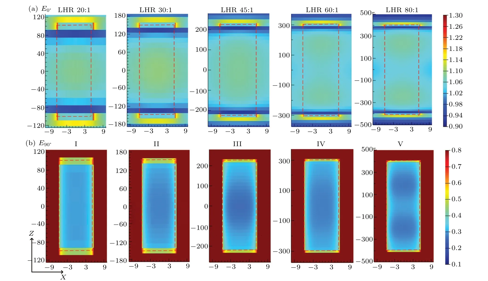
Fig.7.Distribution of the electric field on the longitudinal section plane of NW with different LHRs when the angle θ between the polarization direction of the excitation light and the longitudinal direction of NWs are(a)0° and(b)90°, where the LHR is(I)20:1, (II)30:1, (III)45:1,(IV)60:1,and(V)80:1.The dashed frame indicates the longitudinal section of NW in the middle of the height.
4.Conclusion and perspectives
This work presents a simulation study of the polarization characteristics of ultrathin CsPbBr3NW with triangular,square and hexagonal cross-section shapes.The simulation results show that,along with the increase of the height of crosssection from 2 nm to 25 nm, the polarization ratios of these three nanowires decrease untilT=15 nm, and increase afterwards.Also, along with the increase of the cross-section area up to 100 nm2,the polarization ratios of these three NWs increase too.In general,for the same height or area,the polarization ratios of these NWs followρhexagon>ρsquare>ρtriangle.Therefore,the NW with the hexagonal cross-section should be chosen,where for a cross-section height of 2 nm and a lengthheight ratio of 20:1, the maximal polarization ratio is 0.951.Further, the polarization characteristic of the hexagonal NW with a cross-section height of 10 nm and different LHRs is compared.The result shows that when the LHR is 45:1, the hexagonal NW exhibits the maximal polarization ratio at the longitudinal center of the NW.
It should be commented that the choice of a hexagonal cross-section of NW is reasonable.As reported in Ref.[23],the IRMOF-74 with 1D hexagonal channel has been realized and the pore apertures can be expanded from 1.4 nm to 9.8 nm by adjusting the ligand.Besides,reported in Ref.[21],the procedure encapsulating the perovskite quantum dots in MOF via a two-step reaction has blazed a path to construct perovskite NWs in the MOF channels, where the solvothermal method is applicable for both perovskite and MOF.It should be noticed that, to be applied to optical devices such as light emitters and photoelectric converters, the CsPbBr3NW?MOF should be prepared into composite films.In addition, for other bandgap semiconductor materials, their polarization characteristics could be influenced by the following factors: (1) the dielectric confinement of bandgap semiconductors; (2) the geometric features of bandgap semiconductors, including cross-section shape, cross-section height,cross-section area and length-height ratio;and(3)the preparation methods of bandgap semiconductors.Their specific polarization characteristics need detailed analysis and discussion,which are out of scope of this work.
Above discussions demonstrate the possibility to construct ultrathin CsPbBr3NW in the hexagonal channel of mesoporous MOF and the feasibility of strong polarization characteristics of CsPbBr3NW?MOF composite film, although the encapsulation of CsPbBr3NW array into the MOF channels is still in embryo,which will be our focus for the next work.
- Chinese Physics B的其它文章
- Analysis of cut vertex in the control of complex networks
- Atlas of dynamic spectra of fast radio burst FRB 20201124A
- Investigating the characteristic delay time in the leader-follower behavior in children single-file movement
- Micro-mechanism study of the effect of Cd-free buffer layers ZnXO(X =Mg/Sn)on the performance of flexible Cu2ZnSn(S,Se)4 solar cell
- Thermally enhanced photoluminescence and temperature sensing properties of Sc2W3O12:Eu3+phosphors
- Heterogeneous hydration patterns of G-quadruplex DNA