Influence of carbon sources on the performance of carbon-coated nano-silicon
2023-11-02 08:13:36LinWang王琳NaLi李娜HaoSenChen陳浩森andWeiLiSong宋維力
Chinese Physics B 2023年10期
Lin Wang(王琳), Na Li(李娜), Hao-Sen Chen(陳浩森), and Wei-Li Song(宋維力)
1Institute of Advanced Structure Technology,Beijing Institute of Technology,Beijing 100081,China
2State Key Laboratory of Advanced Metallurgy,University of Science and Technology Beijing,Beijing 100083,China
3Tianjin Lishen Battery Joint-Stock Co.,Ltd,Tianjin 300384,China
Keywords: silicon,carbon coated,different carbon sources,lithium-ion battery
1.Introduction
With the rapid development of the economy and society, natural resources are being constantly consumed.Nonrenewable resources such as oil and natural gas are being increasingly exhausted and become more and more scarce.The lithium-ion battery is proven to be one of the new clean energy technologies to solve the energy problems.[1-3]The anode material is an important component of lithium-ion batteries, and plays a crucial role in electrochemical performance.Many requirements need to be met in an ideal anode material for lithium-ion batteries,such as low chemical potential,good electrical conductivity,good cycling stability,safety,and lowcost raw materials.Owing to the high theoretical energy densities and abundant original material resources, silicon-based anode materials have drawn much attention in the lithium-ion battery research.[4-14]However, intrinsic shortcomings such as drastic volume change during lithiation and delithiation and poor electrical conductivity, have hindered their practical applications.
As is known, carbon coating is an effective approach to improve the electrochemical performance of a silicon anode.[15-18]However,the carbon source,carbon content,and different contact and mixing schemes between carbon sources and silicon can all produce different electrochemical performance.In this case,a systematic study is needed to clarify the influence of carbon on the final performance of batteries.
Herein, nano-silicon with a particle size of 200 nm is used as raw material.The nano-silicon is sintered at 1000°C in different atmospheres for carbon coating by chemical vapor deposition.The selected gases are acetylene, methane,propane, and propylene.Carbon content after carbon coating is controlled to the same level to reduce the experimental error.However,the specific capacity of pure silicon is too high to be directly applied in practical production.In this case,pure carbon-coated nano-silicon mixed with commercial artificial graphite with a designed capacity of 600 mAh/g is prepared and tested, in order to simulate the practical commercial applications.
2.Preparation and characterization
2.1.Preparation of samples
In this research, commercial nano-silicon was used directly.The specific experimental procedures are as follows:200 g of nano-silicon was placed into a rotary hearth furnace,heated to 1000°C with a heating rate of 3°C/min in an Ar atmosphere with a flow rate of 5 L/min, and kept at 1000°C for 1 h in mixed gas.The mixed gases were Ar and acetylene with flow rates of 5 L/min and 1 L/min, respectively.After cooling to room temperature,carbon-coated nano-silicon was obtained.The preparation of carbon-coated materials from different gas sources is similar to that described above.Then,four kinds of carbon-coated nano-silicon with different carbon sources are mixed with the same commercial artificial graphite(graphite accounts for 89%by weight),with a designed capacity of about 600 mAh/g.The final samples are composed of nano-silicon,carbon,and graphite.Properties of the prepared materials and the electrodes are analyzed by different methods,and the schematic diagram is shown in Fig.1.
2.2.Characterization of materials
The morphologies were observed using a scanning electron microscope (SEM, S-4800, Hitachi).The crystal structures were determined using a Bruker D8 Advance diffractor.The carbon content was determined using a Yanrui CS-320 C/S analyzer.
2.3.Half-cell testing
The coin cell testing procedure for nano-silicon/carbon is as follows: nano-silicon/carbon,conductive carbon black and carboxy,methyl cellulose were mixed at a mass ratio of 7:2:1 in DI water to prepare the electrode slurry.The slurry was prepared in a beater at room temperature and spread evenly on the copper foil.After drying in a blast drying oven for 2 h at 50°C, the prepared foil was cut into pieces of 8×8 mm, and dried at 100°C in a vacuum drying oven for 10 h.The dried pole pieces were then transferred to a glove box for battery assembly.The mass loading was about 1.2 mg/cm2.
The assembly of the simulated cells was performed in a glove box containing high-purity Ar, with metallic lithium as the counter electrode, and 1 mol of LiPF6in ethylene carbonate(EC)/dimethyl carbonate(DMC)(v:v=1:1)as the electrolyte.The galvanostatic charge-discharge tests were carried out with a Land automatic battery tester.The discharge cut-off voltage was 0.005 V,and the charge ended at 2 V with a rate of 0.1 C.The first discharge test was carried out at currents of 0.1 C,0.05 C,0.02 C,and 0.01 C.The subsequent cycling discharge tests were carried out at currents of 0.5 C, 0.2 C,0.05 C,and 0.02 C.
The coin cell testing procedure for nanosilicon/carbon/graphite is as follows: nano-silicon/carbon,conductive addictive carbon black, carboxy methyl cellulose,and styrene butadiene rubber(SBR)were mixed at a mass ratio of 93:2:2:3 in DI water to prepare the electrode slurry.The test conditions were the same as for the nano-silicon/carbon sample test described above.
2.4.Full-cell testing
The 18650 cylindrical cells with a capacity of 3.0 Ah were assembled in an Ar-filled glove box with commercial high-nickel ternary material NCM811 as the cathode.The silicon/carbon/graphite composite material was used as the anode.The other components such as electrolyte, copper foil,aluminum foil,and separator are commercial products.
Standard commercial cell production was used in this research.Before electrochemical tests,all cells went through the chemical composition process.In a typical cycle,the cell was charged to 4.2 V at a rate of 1 C,and charged at 4.2 V until the current was lower than 0.02 C.Then,the cell was discharged to 2.5 V at a rate of 1 C.
3.Results and discussion
3.1.Characterization of carbon-coated nano-silicon
X-ray diffraction (XRD) results of the nano-silicon coated from different carbon sources are displayed in Fig.2(a).NS-1 represents uncoated nano-silicon,and typical characteristic peaks of Si are detected.NS-2, NS-3, NS-4, and NS-5 denote nano-silicon coated with acetylene,methane,propane,and propylene, respectively.The overall peak shapes of the four samples are similar to the NS-1 sample,which means the carbon coating does not change the structure of nano-silicon.However, a weaker peak near 26°attributed to carbon can be observed clearly,which is different from the result of the XRD pattern of NS-1.This small peak might come from the coated carbon on the surface of nano-silicon.
Scanning electron microscopy (SEM) is used to analyze the morphologies of nano-silicon samples prepared from different gas sources.As can be seen from Fig.2(c), before the coating,the particle size of nano-silicon is about 200 nm.The particle sizes of nano-silicon after different kinds of carbon coating grow slightly,but the increase is very small.The morphology after coating is still ball-shaped granular.
In order to characterize the conductivities of nano-silicon samples coated using different carbon sources, a powder conductivity test is performed and the results are shown in Fig.2(b).As can be seen from Fig.2(b), the conductivities of the four nano-silicon powders are quite different.NS-2,the nano-silicon powder coated with acetylene, presents the lowest conductivity.NS-3 is the sample coated with methane,and the conductivity is at a medium level.The conductivity of NS-4 (using propane) is higher than that of NS-3, while NS-5 presents the highest conductivity.In addition, the powder conductivity of the uncoated with nano-silicon sample,NS-1,is measured to be only in the order of 10-8-10-7S/cm (not listed in the figure),which is significantly lower than the four coated samples.This result shows that carbon coating can significantly improve the conductivity of a nano-silicon anode.
TEM results of the five samples are displayed in Fig.2(d).In the nano-silicon sample, clear lattice fringes can be observed,which may be the lattices of silicon,while for the four coated samples, the region with relatively disordered lattice fringes may be amorphous carbon surface layers(marked by a rectangle),and the region with obvious lattice fringes may be the lattices of silicon(marked by a circle).
Carbon contents of the four samples are calculated by a carbon and sulfur analyzer to confirm the successful introduction of carbon.It is found that the carbon content of NS-1,NS-2, NS-3, NS-4, and NS-5 are 0%, 14.8%, 15.2%, 15.0%,and 14.7%, respectively, as depicted in Table 1.The results demonstrate that carbon has been successfully introduced into the nano-silicon sample, and the carbon contents of the four coated samples are very close.
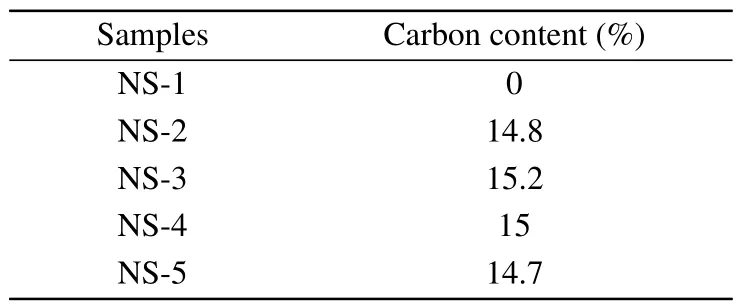
Table 1.Carbon contents of as-prepared samples.
The electrochemical performance of nano-silicon coated with carbon using different gas sources is also tested.Figure 3(a) shows the first-cycle charge-discharge curves of all the samples.The initial discharge capacity of NS-1 is 3391.4 mAh/g with a Coulombic efficiency of 92.2%.After carbon coating, the initial discharge and charge capacities of the four samples both decrease to a certain extent.The charge capacities and Coulombic efficiencies of the first cycle are listed in Table 2.It can be seen that the values of the four samples are all relatively close.At the same time,they are obviously smaller than that of uncoated nano-silicon, since the specific capacity and initial Coulombic efficiency of carbon are lower than that of silicon.Figure 3(b)shows the comparison of the cycle performance of nano-silicon coated by four carbon sources.The uncoated sample presents the poorest cycling stability,while the NS-5 presents the best cycling stability.These results are consistent with the results of the powder conductivities of the samples shown in Fig.2(b), which indicates the sample with higher conductivity presents better cycle performance.
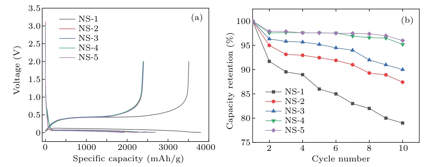
Fig.3.The electrochemical performance of the nano-silicon samples coated by different carbon sources in half cells.(a)Charge-discharge curves of the first cycle,(b)the cyclic performance of the nano-silicon samples.
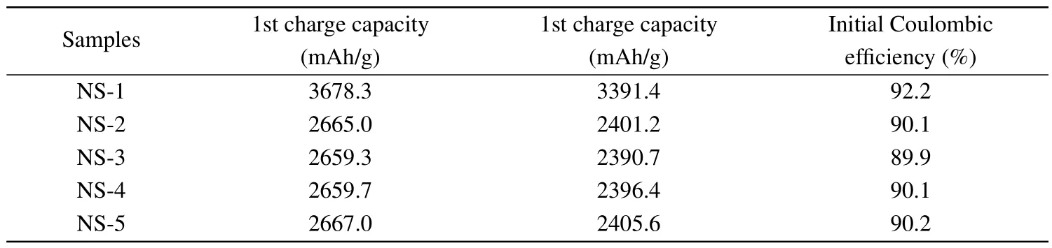
Table 2.The electrochemical performance of the nano-silicon samples coated from different carbon sources.
3.2.Electrochemical performance of practical electrodes with nano-silicon coated from different carbon sources.
Nano-silicon/carbon/graphite composite materials with a designed capacity of about 600 mAh/g after physical blending are named as NS-2-600,NS-3-600,NS-4-600,and NS-5-600.The capacities are tested and the data obtained are shown in Table 3.
Figure 4(a) depicts the charge-discharge curves of the four composites in the first cycle.It can be seen that the specific capacities and initial Coulombic efficiencies of the four samples are very close.Figure 4(b)shows the capacity retention of the four composites in half-cells.It can be concluded that the order for cycling performance from good to bad is NS-5-600, NS-4-600, NS-3-600, and NS-2-600, and the difference between NS-5-600 and NS-4-600 is quite small.This result is consistent with the powder conductivities of the samples,which further illustrates that carbon-coated nano-silicon with higher conductivity performs better during cycling.
It can be seen from Fig.4(c)that after combining silicon with graphite to achieve similar specific capacities, the trend is similar to that of the conductivities of the samples without graphite.Additionally, based on the powder conductivity data, the powder conductivity of the composite after mixing with graphite is significantly higher than that of carbon-coated nano-silicon without graphite.
The cycling performances of the four composites in fullcells(steel shell cylindrical 18650 3 Ah system)are shown in Fig.4(d).As can be seen,cycling performance of nano-silicon coated using four different carbon sources,from best to worst is NS-5-600, NS-4-600, NS-3-600, and NS-2-600.The difference between NS-5-600 and NS-4-600 is small, which is consistent with the results based on half cells.
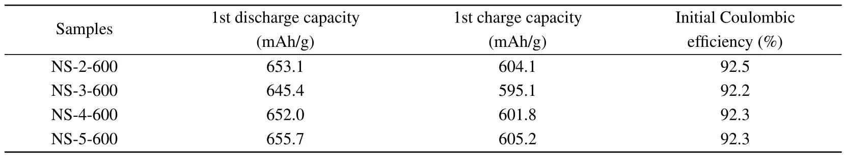
Table 3.The electrochemical performance of the corresponding composites of the nano-silicon samples coated from different carbon sources.
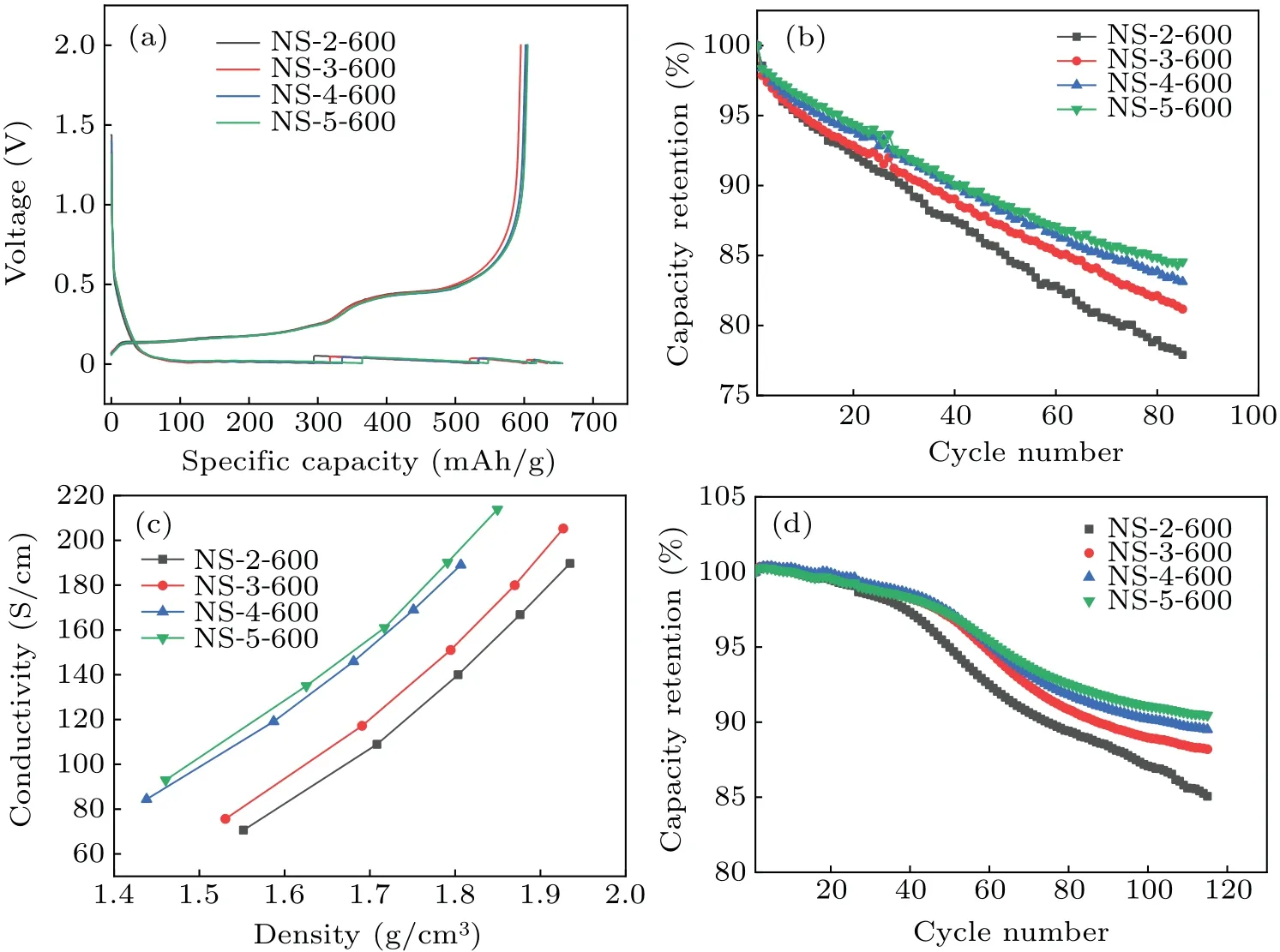
Fig.4.The electrochemical performance of the corresponding composites of the nano-silicon samples coated from different carbon sources.(a) Charge-discharge profiles of the corresponding composites.(b) The cyclic performance of the corresponding composites in half cells.(c)Powder conductivities of the corresponding composites.(d)The cyclic performance of the corresponding composites in full cells.
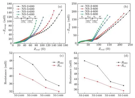
Fig.5.Nyquist plots of the corresponding composites of the nano-silicon samples coated from different carbon sources in half cells: (a)before cycling,(b)after cycling,(c)fitting of RSEI and Rct before cycling,(d)fitting of RSEI and Rct after cycling.
In order to investigate the intrinsic reasons for the different electrochemical performance of the four samples,electrochemical impedances of the four composites before and after cycling are tested, and the results are shown Figure 5.Figures 5(a) and 5(c) exhibit the EIS curve before cycling.Figures 5(b)and 5(d)display the EIS curve after cycling.It can be seen that before and after cycling, the impedance of the four composites,from small to big,is NS-5-600,NS-4-600,NS-3-600, and NS-2-600.This further demonstrates that a carboncoated nano-silicon composite with a lower electrochemical impedance has a better cycling performance.
Nano-silicon samples will have different conductivity and different cycle performance after coating with different carbon sources.Based on the results of our research, there is a relationship between the conductivity and the cycle performance.The sample with higher conductivity also shows higher cycle performance.The reason may be the cell assembled with materials with higher conductivity will have lower electrochemical impedance,which will perform better during the cycles.
4.Summary
In this research, nano-silicon is coated with carbon from four different gas sources.The composites’ conductivity and cycling performance in half and full cells are systematically studied.It is found the sample with higher conductivity also shows higher cycle performance.Propylene is the best choice of the four carbon sources studied in this research.These results indicate that carbon coating with chemical vapor deposition is an effective method to improve the performance of a nano-silicon anode.Meanwhile,the selection of the carbon source is also important and plays a significant role in the electrochemical performance obtained.
Acknowledgements
Project supported by Beijing Natural Science Foundation(Grant No.2182065)and the National Natural Science Foundation of China(Grant No.11922202).
- Chinese Physics B的其它文章
- Corrigendum to“Reactive oxygen species in plasma against E.coli cells survival rate”
- Dynamic decision and its complex dynamics analysis of low-carbon supply chain considering risk-aversion under carbon tax policy
- Fully relativistic many-body perturbation energies,transition properties,and lifetimes of lithium-like iron Fe XXIV
- Measurement of the relative neutron sensitivity curve of a LaBr3(Ce)scintillator based on the CSNS Back-n white neutron source
- Kinesin-microtubule interaction reveals the mechanism of kinesin-1 for discriminating the binding site on microtubule
- Multilevel optoelectronic hybrid memory based on N-doped Ge2Sb2Te5 film with low resistance drift and ultrafast speed