Influencing factors of strut-based RBCC performance in ramjet mode
2016-11-03 01:10:44WANGYajunLIJiangHEGuoqiangQINFei
固體火箭技術 2016年1期
關鍵詞:模態
WANG Ya-jun, LI Jiang, HE Guo-qiang, QIN Fei
(Science and Technology on Combustion, Internal Flow and Thermal-Structure Laboratory,Northwestern Polytechnical University, Xi'an 710072, China)
?
Influencing factors of strut-based RBCC performance in ramjet mode
WANG Ya-jun, LI Jiang, HE Guo-qiang, QIN Fei
(Science and Technology on Combustion, Internal Flow and Thermal-Structure Laboratory,Northwestern Polytechnical University, Xi'an710072, China)
Aiming at two expansion configurations of RBCC combustor, three-dimensional numerical simulation and ground tests were carried out to study the effects of structural parameters and flame stabilization devices on engine performance in ramjet mode. The results show that better combustion reaction and less total pressure loss can be achieved with a smaller expansion angle of the second combustor. Pylons for injection with cavities flame holder in each combustor can effectively enhance combustion of fuel and extend the range of flame propagation. The better performance of thrust increased by 682 N through configuration improvement has been verified with direct-connect test. Moreover, the sustained combustion of fuel after shutting down the rocket could be achieved when the cavities location is close to the pylons, in such a case the specific impulse has a nearly 50% increase with rocket off. Pre-combustion shock train can be more easily established in isolator by reducing the width of central strut atMa=4 and better reaction of subsonic combustion can be ensured, in this case the engine performance has improved by 418 N.
rocket based combined cycle;ramjet mode;performance;influencing factors
0 Introduction
As one of the most promising approaches to realize reused orbit transportation system and near space hypersonic vehicle, Rocket Based Combined Cycle (RBCC) engine takes advantages of high thrust-to-weight ratio of rocket and high specific impulse of ramjet, which makes it suitable for a broad range of airspace flight with the multi-modes integration characteristics[1-2]. Achieving efficient stable work in multi-modes with the fixed flow path is the key technology of this engine. RBCC engine operates in four main modes: ejector, ramjet, scramjet and rocket mode. As the middle mode, the ramjet mode is used from supersonic to hypersonic flight regime, which is a main process of acceleration. With the inlet starting, the incoming air captured and the fuel injected mix and burn in expansion flow path[3]. A thermal throat is formed with the large exothermic quantity of combustion in limited space along with the pre-combustion shock train established in isolator because of the pressure rise in combustor[4]. Due to the low total temperature and total enthalpy of incoming flow condition in ramjet mode, it is difficult to achieve ignition and flame stabilization of fuel, not to mention realizing stable thermal throat through reasonable heat release, which is the key technology of ramjet mode. Therefore how to achieve stable and efficient combustion in expansion duct is one of most important technical challenges needed to be solved.
Until now, many research have developed on RBCC engine, and some valuable achievements and many different engine configurations are achieved. Aerojet's Strutjet adopt the struts across the flow path as it performs the following functions: compressing the incoming air, isolating inlet and combustor, injecting fuel in ramjet and scramjet mode, and embedding rocket engine, which is a highly integrated geometric structure[5]. The combustor of A5 RBCC engine by Rocketdyne company contains a straight section after the isolator step and a expansion section. The rockets are embedded in both sides of the isolator[6]. The GTX engine by NASA has three axial symmetric flow paths and employs a thermal throat whose location is controlled through the distribution of fuel, based on inlet pressure measure[7]. The main characteristic of Japanese RBCC engine is the rocket placed on the upper side of isolator. The incoming air go through the step from isolator into the expansion combustor. Thermal throat is easily formed through combustion in a straight section, which is located at the end of combustor[8]. Even though the research on RBCC engine in China start relatively late, there are many studies in the fields of each mode, which include ejector mechanism, combustion organization, different rocket state in each mode, etc. by means of one-dimensional theoretical analysis, three-dimensional numerical simulation and ground tests and so on[9-11].
In the previous study, the assisting ignition and combustion of fuel in the combustor by the rocket operating at relatively low flow rate and fuel-rich condition have been investigated[12-13]. Stable combustion has also been achieved with fuel injecting pylons and cavity flame holder in ramjet mode[14]. Although ramjet mode has higher specific impulse performance in theory compared with other modes, ramjet of RBCC operating in expansion configuration can't work as efficient as traditional ramjet with a convergent-divergent supersonic nozzle. In order to achieve better efficient combustion in ramjet mode of RBCC, we need a deep understanding on the characteristics of the flame stabilization and combustion organization. Research has been carried out on some influencing factors of strut-based RBCC performance through numerical and experimental methods atMa=3 andMa=4, typical ramjet flight regime.
1 Configuration of RBCC and numerical methods
1.1Configuration of RBCC
The combustor of RBCC engine is an expanding rectangle one (Fig.1). It is consisted of two sections with different expansion ratio. The rocket engine is embedded in the central strut, and it adopt two parallel rectangle nozzles, whose expansion ratio is 6 limited by the width of strut and the pressure of rocket chamber. Two pylons are placed in the down-stream of the rocket nozzle, parallel to the direction of incoming flow. The main difference between configuration 1 and 2 is pylon, cavity and the expansion angle. Configuration 2 has longer pylons (throughout the height of combustor), the smaller expansion angle of the second combustor and two groups of cavities with length-to-depth ratio equal to 3 arranged in the two sections respectively. The ground experiment facility also include a facility nozzle behind the isolator that can simulate different Mach number of incoming flow and a divergent duct as the internal nozzle.
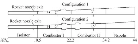
Fig.1 Configuration of RBCC engine
1.2Numerical methods
Numerical investigations in this paper are carried out by software Fluent. Three-dimensional unsteady Reynolds time-averaged Navier-Stokes (N-S) equations are chosen as the control equations, while SSTk-ωmodel for viscous model that has a short calculation period and high calculation accuracy for the turbulence in the free shear flow and the flow separation. A simplified three-step kinetic model[14]of kerosene JP-10 whose molecular formula is C10H16is used for the calculations of chemical reaction rate. The Lagrange two-phase flow method is used for liquid fuel injection and TAB model for droplets broken. A calculation of 1/2 region is carried out because of the structural symmetry. Structured grids are adopted except for a small part region of complex structure. Besides, mesh refinement is used in the region of complex flow and structural variation. No slip adiabatic wall is also employed. The total grids for numerical simulation in this paper reach 1.4 million.
1.3Numerical validation
The validation of numerical methods on RBCC combustor is based on the experiment data of direct-connect test in Science and Technology on Combustion, Internal Flow and Thermal-structure Laboratory of Northwestern Polytechnical University using the RBCC engine configuration 2, whose simulated operation condition is set at the flight height of 12 km, andMa=3. The flow rate of incoming air is 4.6 kg/s, while the mass flow rate of liquid alcohol/gas oxygen is set to 160 g/s. Additionally, the fuel in the test is selected as JP-10, which is injected into the flow path from the two pylons with the equivalent ratio of 0.7. Expected for the small region after the pylons in which there is a certain deviation because of the simplified chemical kinetic model of kerosene that cannot reflected the real complex flow field of the combustion reaction, the contrast (Fig.2) indicate that the CFD pressure distributions along the RBCC combustor keep consistent with the test data on the whole, wherePiis the static pressure at isolator entry andHis the height of combustor entry. Consequently, the numerical methods in this paper are credible for simulations on the flow fields of RBCC combustor.
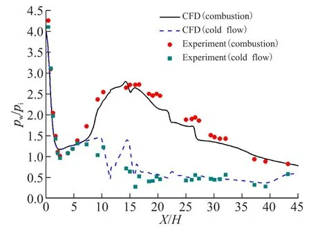
Fig.2 Pressure distribution contrast between CFD
2 Comparison of two configurations
2.1Expansion angle of combustor
As known, typical dual mode scramjet usually has a two-stage combustor, which play different role in each stage. According to the characteristics of RBCC, the first combustor is the main exothermic area when rocket working in ejector mode or working as a pilot flame in ramjet mode. In order to ensure combustion reaction maintained in a more stable flow, a small expansion angle of first stage has always been chosen. However, pressure rising caused by too small expansion angle will definitely influence the entrainment ratio of air in ejector mode or the operating state of inlet in ramjet mode. Therefore the expansion angle of 2° and expansion ratio of 1.4 are chosen for the first combustor.
The second combustor mainly provides an afterburning chamber for the fuel that has not completely reacted. So the chemical energy of fuel can be more fully utilized. On the other hand, the formation of stable thermal throat in this section means the chemical energy and pressure potential energy can be effectively changed into engine thrust. Numerical simulation has been carried out to study the performance of different expansion angle from 1.5° to 3° of the second combustor.
As the increase of expansion angle leads to the decrease of secondary combustion (Fig.3) and larger total pressure loss (Fig.4). That means bigger expansion angle reduce the afterburning ability of fuel, moreover, lead combustion gas mainly to accelerate, resulting in energy loss with speeding. For ramjet mode, especially, it's harder to form a stable thermal throat without enough heat release in the second combustor. Therefore the expansion angle of 1.5° and expansion ratio of 1.2 are chosen for the second combustor.
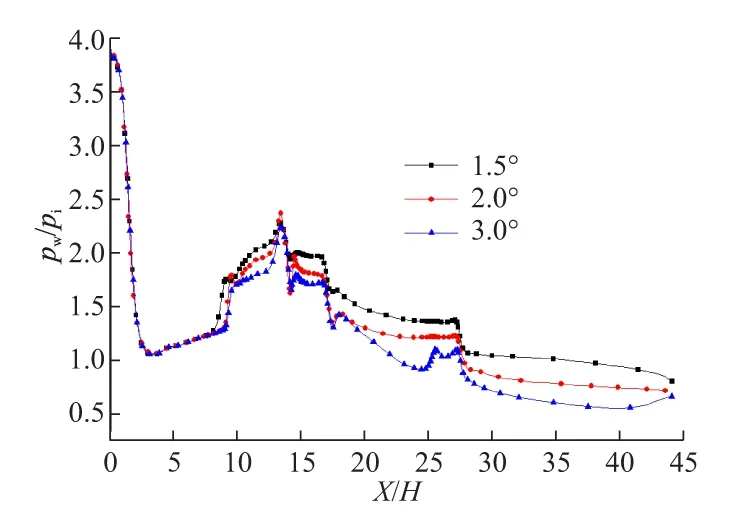
Fig.3 Pressure distributions along the wall of
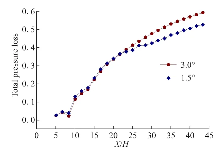
Fig.4 Total pressure loss of different
2.2Cavity
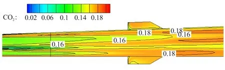
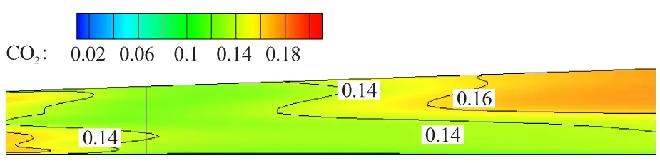
Many studies have demonstrated that cavity could effectively be used as flame holder both for ramjet and scramjet combustor[15-16], not excepting RBCC. The idea behind is that the cavity traps a strong and stable vortex and provides a favorable condition for ignition resulting in ignition delay time decreasing. Experiment and numerical simulation of a different numbers of cavities are performed to explain the role of cavity in RBCC combustor. Each cavity has the same structure with a depth of 25 mm and length-to-depth ratio is equal to 3. Static pressure distribution along the combustor show that engine performance with one cavity is better than the one without cavity structure (Fig.5) and two groups of cavities are relatively better than only one group (Fig.6). An effective combustion region is formed in the second combustor with a group of cavities that improve further reaction of fuel with air and flame propagation. With flame stabilization region formed in cavities, flame spreading to both sides of combustor is promoted, thereby increasing the utilization of air and improving combustion efficiency. The comparison of oxygen and carbon dioxide distribution in the second combustor are showed in Fig.7 and Fig.8. Further mixing of fuel with air and flame stabilization source can't be achieved without the second cavities, thereby reducing the efficient use of the chemical energy of fuel. In summary, static pressure curves definitely illustrate the importance of the cavities arranged in both combustors on the performance of RBCC combustor.
2.3Pylon
Pylon is another device of flame stabilization or fuel injection often used in ramjet or scramjet combustor[17-18].
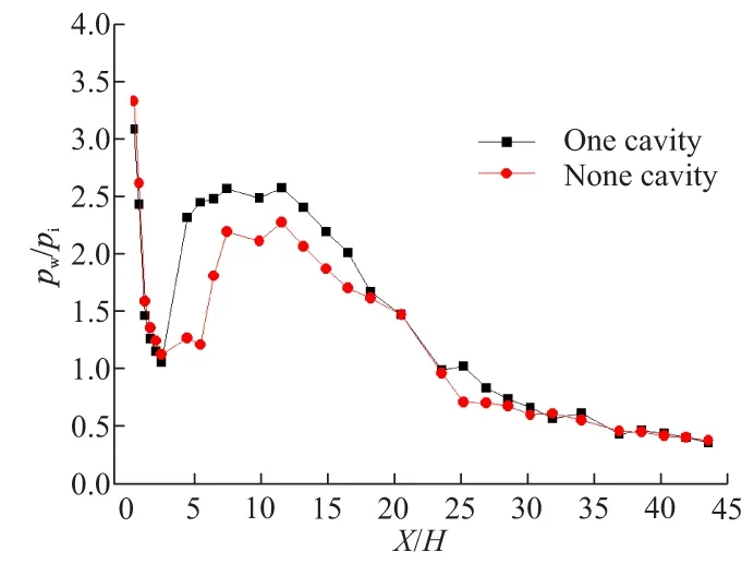
Fig.5 Pressure distributions along the wall with
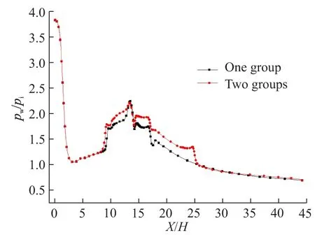
Fig.6 Pressure distributions along the wall with one
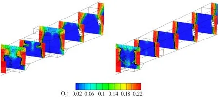
(a) Two groups (b) One group
(a) Two groups
(b) One group
The fuel pylons with stream-wise vortex in tail are adopted in the combustion organization working with the cavity groups under wide flow conditions. The problem of penetration depth in a larger flow path can be solved by using pylons. Fuel can be injected directly into the mainstream to mix and combust. Additionally, the shear layer formed by pylons in the high-speed flow enhance the turbulence intensity, the substance exchange, and the fuel-air mixing efficiency. The fuel is fairly distributed throughout the height of combustor with longer pylons, forming a larger combustion region as showed in Fig.9, coupled with two cavities in combustor. The mixing region formed after the pylons and the flame stabilization region formed by cavities are connected together, fusing the upper and lower surface with the central region of flow path to form a larger area of combustion. The ability of flame propagation is substantially strengthened in the whole duct, thereby improving the combustion efficiency of fuel. Therefore, the combustion organization using pylons with cavities in combustor is an effective method to improve the performance of RBCC engine.
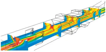
(a) X and Y plane
(b) Z plane
2.4Experiment validation on improvements
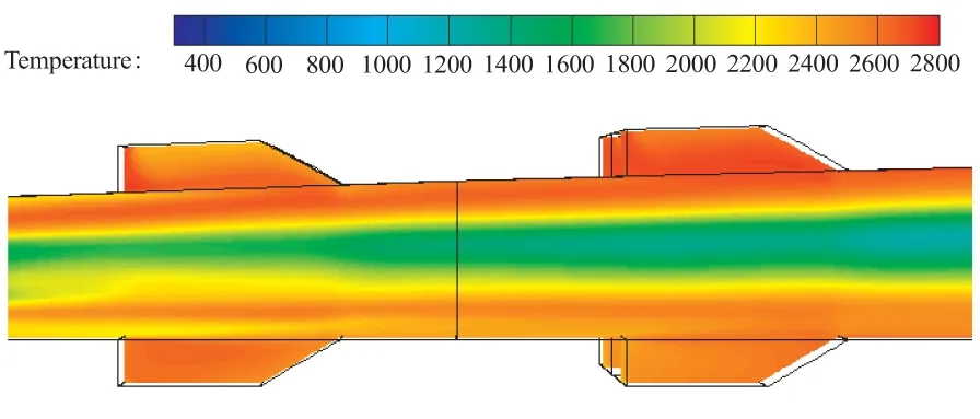
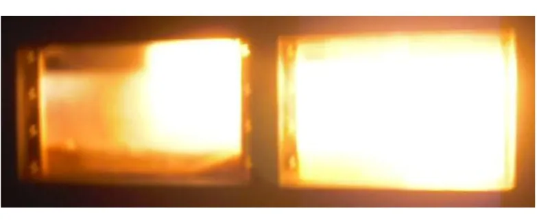
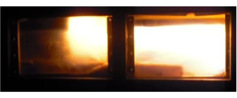
To validate the mentioned above improvements on the engine performance, ground test atMa=3 has been carried out with these two configurations. The total pressure and temperature of incoming air are 0.65 MPa and 620 K respectively, while the mass flow rate of rocket is set to 160 g/s and the equivalent ratio of kerosene fuel is 0.7. Results show that the performance of improved configuration has been greatly enhanced (Fig.10) within the almost same length of combustor. Configuration 1 has a larger and relatively disordered flame at the exit from the surveillance video(Fig.11), but in contrast configuration 2 has a significantly smaller flame and obvious Mach disk. These phenomena indicate that configuration 2 has higher combustion efficiency, while a stable thermal throat is formed in the combustor and flow is accelerated to supersonic at the exit. That also could be seen from Mach distributions in the combustor through numerical simulation (Fig.12) in which the subsonic incoming flow at the entrance and longer subsonic combustion region of configuration 2 mean the formation of thermal throat and better combustion of fuel. The thrust is improved by 682 N compared to the previous configuration, shown in Table 1 wheremris the mass flow rate of rocket andφis the equivalent ratio of kerosene fuel.
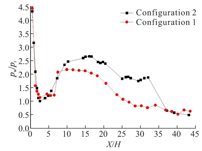
Fig.10 Pressure distributions along the wall between
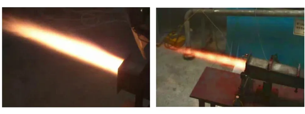
(a) Configuration 1 (b) Configuration 2
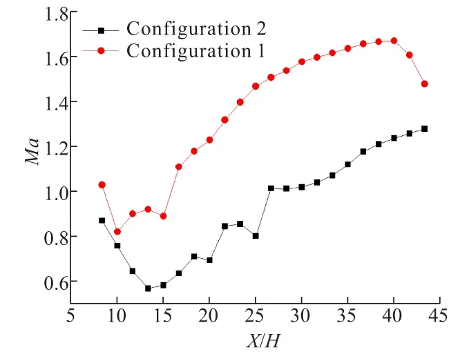
Fig.12 Average Mach distributions in the combustor
3 Other influencing factors
3.1Rocket
As an important part of RBCC engine, rocket plays different roles at different modes. Compared to the traditional ramjet engine, reliable ignition of hydrocarbon fuel in the flow condition of low total temperature and the role of flame source at high Mach could be achieved by the rocket jet of high temperature in RBCC engine. Besides, high combustion efficiency, flame stability and power management at different flight conditions could be achieved by adjusting the operating state of the rocket. The jet of rocket works as a leading flame in ramjet mode that provides a continuous source of ignition, greatly reduces the ignition delay time and enhances combustion reaction speed of fuel. However, the rocket may have a negative impact on the overall specific impulse and it has limited thrust gained during the ramjet mode.
Fig.13 showes the time sequence in a typical experiment during which the rocket is closed after 5 seconds. Combustion process and flame structure at different times are shown in Fig.14 from which we can see that fuel is ignited immediately by the jet flame of rocket and a large high temperature region is established in the flow path. However, the flame of fuel soon go out after the rocket being closed because of the low total temperature of incoming flow atMa=3.
In order to improve the specific impulse of RBCC engine in ramjet mode, more experiments have been carried out to ensure the sustained combustion of fuel without jet flame. The sustained burning could be achieved when the cavities location is close to the pylons (Fig.15), which means the propagating ability towards upstream of cavity flame is limited and the cavity must acquire sufficient combustible mixtures before the flame spreads out in order to ensure continuous combustion in the recirculation zone of cavity. The specific impulse has a nearly 50% increase with rocket off when the flow rate ratio between fuel and rocket is 1.43.
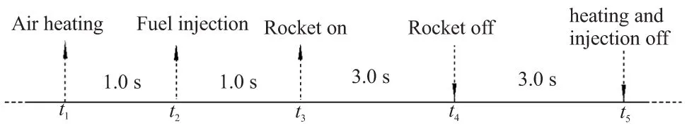
Fig.13 Experiment time sequence at Ma=3
3.2Central strut
For strut-based RBCC engine like configuration 2, there is a strut embedded in the central of the flow path that causing a step from isolator to combustor.
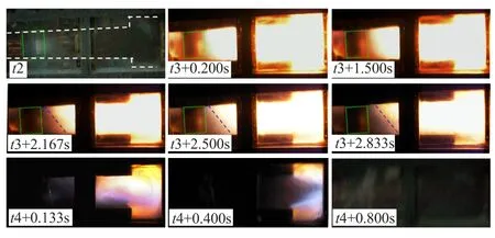
Fig.14 Combustion process and flame structure
(a) Rocket on
(b) Rocket off
It is very hard for the back pressure of combustor propagating into isolator if the step is too deep, which makes harder to establish shock train in isolator with incoming flow Mach number increasing. For ramjet mode, the formation of subsonic incoming flow in isolator is the guarantee of highly efficient combustion and less total pressure loss in combustor. Comparative study is performed between two struts of different width through numerical simulation. The blockage ratio of two struts is 0.44 and 0.3 respectively. Shock train is easier formed in the isolator atMa=4 with a narrower strut through numerical research (Fig.16).
At the same time, a higher combustion performance could be also obtained (Fig.17). Additionally, the effect of strut width on engine performance at lower Mach number is also performed by ground test. The decrease of strut width don't have an impact on the combustion in combustor in the experiment atMa=3, but only make the back pressure of combustor propagate more forward in the isolator and not affect the working status of inlet (Fig.18). These studies show that it is reasonable and feasible to improve RBCC engine performance in ramjet mode through decreasing the width of strut. The thrust is improved by 418 N atMa=4, as shown in Tab.1.
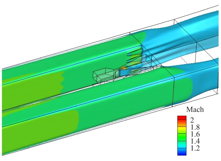
(a) Strut 44%
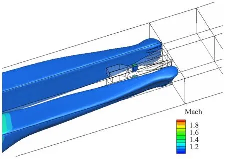
(b) Strut 30%
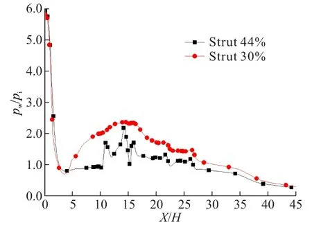
Fig.17 Pressure distributions along the wall with
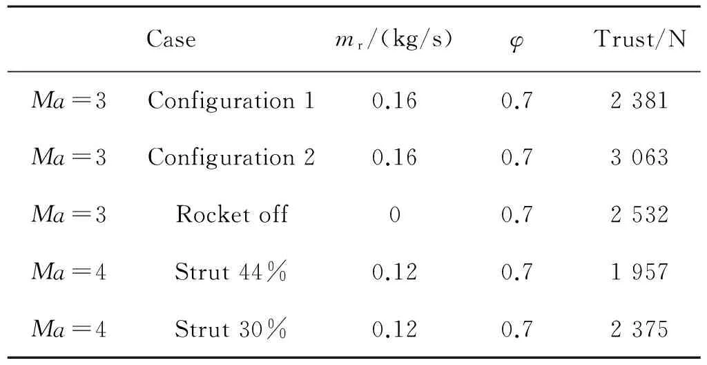
Casemr/(kg/s)φTrust/NMa=3Configuration10.160.72381Ma=3Configuration20.160.73063Ma=3Rocketoff00.72532Ma=4Strut44%0.120.71957Ma=4Strut30%0.120.72375
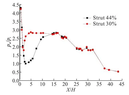
Fig.18 Pressure distributions along the wall
4 Conclusion
Through numerical simulations and ground tests of different influencing factors on strut-based RBCC engine performance in ramjet mode, some conclusions are drawn as follows:
(1) With the decrease of expansion angle, the ability of further combustion in the second combustor increase and the total pressure loss reduce. Therefore the overall performance of RBCC engine is improved.
(2) The cavity can effectively enhance the combustion in the RBCC combustor. The results of by numerical simulations show that engine performance with one cavity is better than the one without cavity and two groups of cavities are relatively better than only one group.
(3) Through reducing the expansion angle of the second combustor, using longer pylons and two groups of cavities in each combustor, the engine performance of configuration 2 is improved by 682 N compared with configuration 1, which is validated by ground test.
(4) The rocket jet of high temperature works as a leading flame in ramjet mode that provides a continuous source of ignition. In some case, shutting down the rocket, when the fuel has been ignited, is a simple and feasible way to improve the specific pulse of RBCC engine. Experiment results show that the sustained combustion could be achieved when the cavities location is close to the pylons. The specific impulse has a nearly 50% increase with rocket off.
(5) The wider strut lead to the pre-combustion shock train in isolator locate closer to combustor, which make harder to establish subsonic combustion in combustor with incoming flow Mach number increasing. Through reducing the width of the central strut, better performance of RBCC engine is achieved by 418 N atMa=4.
[1]Russell Daines,Corin Segal.Combined rocket and airbreathing propulsion systems for space launch applications[J]. Journal of Propulsion and Power,1998,14(5).
[2]Qin Fei,Lv Xiang,Liu Pei-jin,et al.Research status and perspective of rocket based combined cycle propulsion system[J].Journal of Propulsion Technology,2010,31(6).
[3]Corin Segal.The scamjet engine: processes and characteristics[M].USA:Cambridge University Press,2009.
[4]David Riggins,Regan Tackett,Trent Taylor.Thermodynamic analysis of dual-mode scramjet engine operation and performance[R].AIAA 2006-8059.
[5]Bulman M,Siebenhaar A.The strutjet engine: exploding the myths surrounding high speed airbreathing propulsion[R].AlAA 95-2475.
[6]Smart M K,Trexler C A,Goldman A L.A combined experimental/computational investigation of a rocket based combined cycle inlet[R].AIAA 2001-0671.
[7]Thomas S R,Palac D T,Trefny C J,et al.Performance evaluation of the NASA GTX RBCC flow path[R]. NASA/TM-2001-210953.
[8]Takeshi Kanda,Kouichiro Tani,Kenji Kudo.Conceptual study of a rocket-ramjet combined-cycle engine for an aerospace plane[J].Journal of Propulsion and Power,2007,23(2).
[9]Li Yu-fei.Thermal adjustment mechanism research on ejector and ramjet mode of RBCC[D].Xi' An:Northwestern Polytechnical University,2007.
[10]Yu G,Li J G,Chang X Y,et al.Investigation of kerosene combustion characteristic with pilot hydrogen in model supersonic combustor[J].Journal of Propulsion and Power, 2001,17(6).
[11]Liu Xiao-wei,He Guo-qiang,Liu Pei-jin,et al.Invetigation of ignition and flame stability in RBCC ramjet mode[J].Journal of Solid Rocket Technology, 2010,33(5).
[12]Pan Ke-wei,He Guo-qiang,Liu Pei-jin,et al.Influence of combustion stabilization by primary rocket under commix-combustion mode in RBCC[J].Journal of Propulsion and Technology,2010,31(5).
[13]Xu Chao-qi,He Guo-qiang,Liu Pei-jin,et al.Experiment of primary rocket-piloting combustion under ramjet-mode condition in RBCC[J].Journal of Aerospace Power, 2013,28(8).
[14]Pan Ke-wei,He Guo-qiang,Qin Fei,et al.Combustion performance of RBCC engine with pylon and cavity at ramjet mode[J].Journal of Propulsion and Technology, 2012,33(2).
[15]Onur Tunce.Combustion in a ramjet combustor with cavity flame holder[R].AIAA 2010-1532.
[16]Ding Meng.Research on the flame holding technology based on cavity in supersonic combustion[D].Chang Sha:Natinal University of Defense Technology,2005.
[17]Manna P,Behera Ramesh,Chakraborty Debasis.Fueled strut-based scramjet combustor design a computational fluid dynamics approach[J].Journal of Propulsion And Power,2008,24(2).
[18]Saito R,Araki S,Sakaue S.Mixing enhancement on the afterburner with fuel injection struts for hypersonic vehicle[R].AIAA 2011-2328.
(編輯:薛永利)
支板火箭RBCC亞燃模態性能的影響因素
王亞軍,李江,何國強,秦飛
(西北工業大學 燃燒、熱結構與內流場重點實驗室,西安710072)
針對2種擴張流道的RBCC燃燒室構型,通過三維數值模擬和地面直連試驗,研究了燃燒室結構參數以及火焰穩定裝置等對亞燃模態性能的影響。結果表明,第二級燃燒室采用較小的擴張角,有利于燃料的進一步燃燒,減小總壓損失,燃料支板和凹腔火焰穩定器的共同使用,能有效提升燃燒室內的燃燒組織效果,擴展火焰的傳播范圍;直連試驗驗證了通過構型的改進,燃燒室性能得到大幅提高,壓力積分推力增大了682 N。當凹腔距離燃料支板較近時,火箭關閉之后,燃料能夠實現自持燃燒,比沖性能可提高50%。通過減小主支板寬度,在來流Ma=4時,能夠更容易在隔離段中建立預燃激波系,保證亞燃燃燒反應更好地進行,燃燒室內推力提高了418 N。
火箭基組合循環;亞燃模態;性能;影響因素
date:2015-03-02;Revised date:2015-05-19。
V438Document code:AArticle ID:1006-2793(2016)01-0009-08
10.7673/j.issn.1006-2793.2016.01.002
Biography:WANG Ya-jun(1987—),male, Ph.D candidate, speciality: for Propulsion Theory and Engineering of Aeronautics and Astronautics. E-mail:nwpu802wyj@gmail.com
猜你喜歡
成都信息工程大學學報(2022年4期)2022-11-18 07:31:14
中國傳媒大學學報(自然科學版)(2021年1期)2021-06-09 08:43:12
工程與建設(2019年1期)2019-09-03 01:12:12
廣州大學學報(自然科學版)(2016年2期)2017-01-15 13:43:00
廣西科技大學學報(2016年1期)2016-06-22 13:10:37
湖北經濟學院學報·人文社科版(2015年8期)2015-12-29 05:53:07
上海電機學院學報(2015年4期)2015-02-28 14:30:00
計算物理(2014年2期)2014-03-11 17:01:39
振動工程學報(2014年4期)2014-03-01 01:15:31
電影新作(2014年1期)2014-02-27 09:07:36