
Formation of electron depletion layer and parallel electric field in the separatrix region of anti-parallel magnetic reconnection?
2019-08-06 02:07:16ZishengLi李子圣HuanyuWang王煥宇andXinliangGao高新亮
Chinese Physics B 2019年7期
Zisheng Li(李子圣), Huanyu Wang(王煥宇),?, and Xinliang Gao(高新亮)
1CAS Key Laboratory of Geospace Environment,School of Earth and Space Sciences,University of Science and Technology of China,Hefei 230026,China
2CAS Center for Excellence in Comparative Planetology,Hefei 230026,China
Keywords: magnetic reconnection,separatrix region,electron depletion layer
1. Introduction
During the topological rearrangement of magnetic field lines occurring in the magnetic reconnection, in addition to the well-known dissipation from magnetic energy into plasma kinetic energy,[1-6]the production of superthermal electrons is also an important ingredient.[7-16]The reconnection electric field in the vicinity of the X line was considered to be the only site to account for electron acceleration during magnetic reconnection until the existence of the parallel electric field was revealed by Wang et al.with cluster observation.[17]Recently,the characteristics of the separatrix region have been gaining more and more attention.[18-24]
The separatrix region separates the ion diffusion region into the inflow and outflow regions. The ions flow toward the X line in the inflow region and move away from the X line in the outflow region.[25,26]However, because the electrons are frozen in the magnetic field while the ions are unmagnetized,the electron motions are different from those of ions.[18,26,27]The electrons move toward the X line in the separatrix region,and are then accelerated by the inductive electric field near the X line; at last, they are directed away along the magnetic field in the region,which is closer to the center of the current sheet.[7-9]This current system leads to a quadrupole structure of the Hall magnetic field (perpendicular to the reconnection plane).[25-33]At the same time, an electron depletion region where the electron density is smaller than in the nearby regions is formed in the separatrix region,which results in a net positive charge therein and an electric field pointing to the center of the current sheet.[34-36]Recently, satellite observations revealed the existence of a parallel electric field in the separatrix region, which indicates that the separatrix region also plays an important role in electron acceleration.[17,37]In this paper,with two-dimensional(2D)particle-in-cell(PIC)simulations,we study the formation of the parallel electric field,as well as the electron depletion layer in the separatrix region. The influences of the ion-to-electron mass ratio and light speed are also investigated.
2. Simulation method
In our 2D PIC simulation model,the electromagnetic field defined on the grids are calculated by an explicit algorithm of Maxwell equations,and the movement of particles is governed by the Lorentz force. The particles can only move in the x-z plane, and their velocities have three components. The details of our simulation model can be found in Ref. [8], and the code has been widely used to study magnetic reconnection and plasma waves.[38-43]The initial configuration is a onedimensional Harris current sheet in the reconnection plane(the x-z plane). The magnetic field and plasma density are given by the following equations:
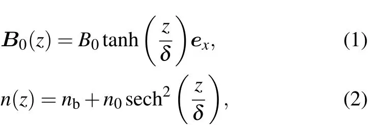
where B0is the asymptotical magnetic field, nbrepresents a uniform background plasma density, and n0is the peak value of the plasma density corresponding to the Harris current sheet. δ is the half width of the current sheet.
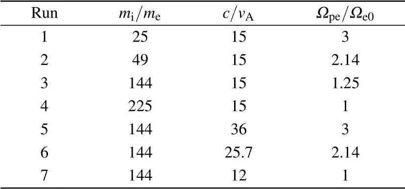
Table 1. Simulation parameters for runs 1-7.
Both ion and electron distributions satisfy the Maxwell function, and their drift velocities along the y direction satisfy Vi0/Ve0=-Te0/Ti0, where Vi0(Ve0) and Ti0(Te0) represent the drift velocity and the initial temperature of ions(electrons),respectively. The simulation domain is Lx×Lz=25.6di×12.8di(where di= c/Ωpiis the ion inertial length based on n0). The number of grids is 1024×512, and then the grid size is Δx=Δz=0.025di. In our simulations, we choose δ =0.5c/Ωpi, nb=0.2n0, Ti0/Te0=1, and the time step is Ωi0Δt=5.0×10⁻³(where Ωi0is the ion gyrofrequency based on B0). The ion-to-electron mass ratio mi/me, the ratio of the light speed to the Alfv′en speed c/vA(where vAis the Alfv′en speed based on B0and n0),and the corresponding Ωpe/Ωe0(where Ωpeis the electron plasma frequency based on n0)are listed in Table 1.The periodic boundary condition is used in the x direction;meanwhile,particles are reflected when they reach the boundary in the z direction and the conducting boundary condition is used for the electromagnetic field.More than 100 million particles are used in the simulations. Magnetic reconnection is initiated by a small flux perturbation.
3. Simulation results
We first describe the characteristics of the separatrix region in run 3. In run 3, the ion-to-electron mass ratio is mi/me=144,and the light speed is c/vA=15. Figure 1 plots the time evolution of the reconnected flux ψ for run 3. The reconnection electric field can be estimated by calculating the slope of the reconnection flux. From the figure, it is easy to find that the magnetic field lines begin to be reconnected at about Ωi0t =15, and the reconnection rate (the reconnection electric field at the X line)attains the maximum value at about Ωi0t=17.2.
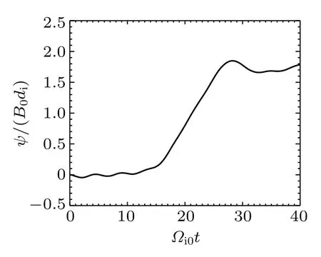
Fig.1. The time evolution of the reconnected flux ψ for run 3.
Figure 2 shows the electron number density neand parallel electron bulk velocity Ve‖at Ωi0t =15,17.5,20,and 26.5 for run 3. The magnetic field lines are also shown in the figure in order to more clearly display the evolution of the electron number density and parallel electron bulk velocity. With the occurrence of magnetic reconnection at about Ωi0t =15,the electrons in the separatrix region flow toward the X line while they tend to be away from the X line along the magnetic field in the region,which is closer to the center of the current sheet. As demonstrated in Ref. [18], such an electron flow will result in an electron depletion layer in the separatrix region. Therefore, with the proceeding magnetic reconnection,an electron depletion layer is formed in the separatrix region at about Ωi0t =16. After the reconnection rate attains the maximum value, the electron flow toward the X line begins to be weaker and weaker, and then disappears. However, the electron depletion layer can last for a much longer time.
The formation of the electron depletion layer can be exhibited more clearly in Fig. 3, which presents the electron number density nealong the grey lines(at x=22.5diparallel to the z axis)denoted in the left panels of Fig.2 at Ωi0t =15,17.5, 20, and 26.5 for run 3. In order to display these values more clearly, we only plot them from z=1.0dito z=6.0dialong the denoted lines. The separatrix region will move away from the center of the current layer as the magnetic reconnection continues. After analyzing the difference between the electron number density neand the Gaussian fit for ne,we can estimate the width of the electron depletion layer in the separatrix region as 1.2di-1.5di. The minimum value of the electron density, which can be attained in the separatrix region at almost the same time as when the reconnection rate reaches the maximum value,is about 0.16n0.
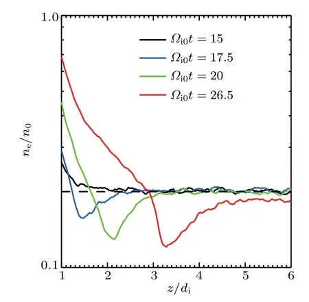
Fig.3. The electron number density ne along the grey lines denoted in the left panels of Fig.2 at Ωi0t=15(black solid line),17.5(blue solid line),20(green solid line),and 26.5(red solid line)for run 3. The initial electron density in the inflow region nb=0.2n0 is indicated by the black dashed line in the figure.
Figure 4 shows the time evolution of the parallel electron bulk flow velocity Ve‖along the grey lines denoted in the right panels of Fig.2 for run 3. We only plot the profile of Ve‖from z=0dito z=6.0dialong the denoted lines. At Ωi0t =17.5,the reconnection rate reaches the maximum value,and the parallel electron flow toward the X line also obtains a maximum value in the separatrix region,which is about 1.1vA. The maximum value of the parallel electron flow away from the X line occurs later at Ωi0t=26.5,and is about-3.2vA.
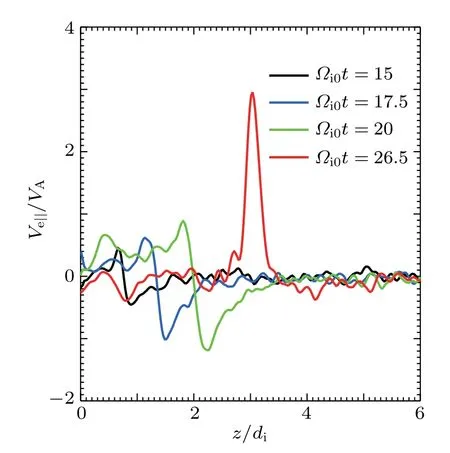
Fig.4. The parallel electron bulk flow velocity Ve‖ along the grey lines denoted in the right panels of Fig.2 at Ωi0t=15(black solid line),17.5(blue solid line),20(green solid line),and 26.5(red solid line)for run 3.
Figures 5(a) and 5(b) respectively describe the parallel electric field E‖and the parallel electrostatic potential Φ‖along the separatrix in the first quadrant at Ωi0t=15,17.5,20,and 26.5 for run 3. Here,the electrostatic potential is defined as Φ‖(l)=∫lXE‖dl,which is integrated along the separatrix in the first quadrant from the X line. Please note that the gradient of Φ‖perpendicular to the magnetic field has physical significance,and Φ‖is only a pseudo-potential that measures the work done by the electric field as an electron moves along the magnetic field line. Obviously, there exists the parallel electric field along the separatrix. At Ωi0t =15, the parallel electric field points away from the X line, and its amplitude becomes large as magnetic reconnection continues until the reconnection rate decreases. However,from about Ωi0t =17,the parallel electric field pointing toward the X line is developed near the X line. The electron flow can be accelerated in the direction along the separatrix toward the X line by the positive parallel electric field. However,in the vicinity of the X line,the negative parallel electric field,which points toward the X line,will block the electron inflow.
The spatial distributions of net charge in the simulation domain for run 3, measured by (ni-ne)/n0, are shown in Figs. 6(a) and 6(b) at Ωi0t =17.5 and 20, respectively. It can be found that the net charge is positive in the separatrix region,which is caused by the depletion of the electron density.However,we can find that in the pileup region the net charge begins to be negative after the reconnection rate reaches the maximum value, and it is formed when the accelerated electrons from the X line are blocked. Such distribution of the net charge results in the parallel electric field described in Fig.5.
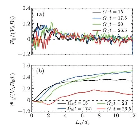
Fig.5. The profiles of(a)the parallel electric field E‖ and(b)the parallel electrostatic potential Φ‖ along the separatrix in the first quadrant at Ωi0t =15(black solid lines),17.5(blue solid lines),20(green solid lines),and 26.5(red solid lines)for run 3. In the figure,the distance Ls is measured from the X line along the upper-right separatrix.
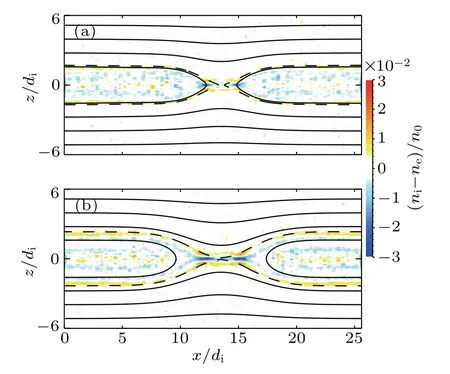
Fig.6. The spatial distribution of net charge in the simulation domain for run 3 at (a) Ωi0t =17.5 and (b) Ωi0t =20. The separatrices are indicated by the black dashed lines.
We further investigate the formation of electron flow along the separatrix for run 3. According to the guiding center theory, the electron parallel acceleration dv‖/dt is given by the following equation:[44]
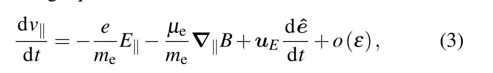
where μeis the electron magnetic moment, uEis the E×B drift velocity, ^e is B/B, and o(ε) represents the small term proportional to me/e. If we sum over all electrons in a local region and neglect the small term o(ε),equation(3)becomes
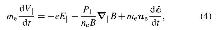
where V‖is the electron parallel bulk velocity summed over the local region,P⊥is the electron perpendicular pressure,and neis the electron number density in the local region. If we assume that the reconnection is in a steady state,equation(4)can be further simplified as
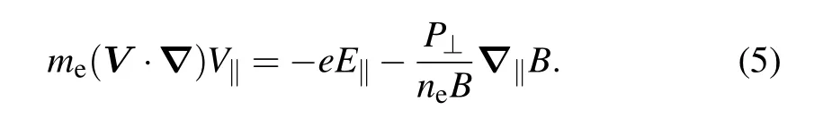
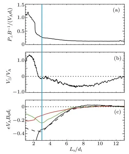
Fig. 7. (a) The profiles of the electron magnetic moment summed over the local region P⊥/B along the separatrix in the first quadrant at Ωi0t =26.5. (b) The parallel electron flow velocity V‖ along the separatrix in the first quadrant at Ωi0t = 26.5. (c) The integration of parallel electric field force -∫ll0 eE‖dl (green solid line),magnetic mirror force -∫l l0 P⊥?‖B/(neB)dl (red solid line), the sum
The left-hand side of Eq. (5) is the convective derivation of electron flow, which is balanced by the parallel electric field force-eE‖and the magnetic mirror force-P⊥?‖B/(neB)on the right-hand side of Eq.(5).l (black dashed line), and the electron convective derivation∫ll0me(V ·?)V‖dl (black solid line)along the separatrix in the first quadrant at Ωi0t =26.5. In the figure,the distance Lsis measured from the X line along the upper-right separatrix.
Figure 7(a)shows the electron magnetic moment summed over the local region P⊥/B along the separatrix in the first quadrant at Ωi0t =26.5 for run 3. The electron parallel bulk velocity V‖along the same separatrix is shown in Fig. 7(b).The integration of parallel electric field force -(green solid line) along the separatrix in the first quadrant is shown in Fig.7(c),where l0is the end point of the separatrix on the right boundary of the simulation domain. The integration of magnetic mirror force-∫dl(red solid line) is also shown in Fig. 7(c). It can be found that from the inflow region to the reconnection X line along the separatrix, both the parallel electric field force and the magnetic
Fig.8. (a)The time evolution of the reconnected flux ψ for run 1(black solid line),run 2(blue solid line),run 3(green solid line),and run 4(red solid line). (b)The time evolution of the reconnected flux ψ for run 5(black solid line), run 6 (blue solid line), run 3 (green solid line), and run 7(red solid line).
Figures 9(a)and 9(b)show the electron number density neand the parallel electron bulk flow velocity Ve‖along the line at x=22.5di,parallel to the z axis for run 1 at Ωi0t=21.25,run 2 at Ωi0t=19,run 3 at Ωi0t=17.5,and run 4 at Ωi0t=16.5.At these times,the reconnection rates of all runs reach the maximum. With the increase in the mass ratio,the electron depletion layer, as well as the parallel electron bulk flow velocity toward the X line in the separatrix region and away from the X line, become more salient. Figures 10(a) and 10(b) show the electron number density neand the parallel electron bulk flow velocity Ve‖along the line at x=22.5di, parallel to the z axis for run 5 at Ωi0t =21, run 6 at Ωi0t =19.5, run 3 at Ωi0t =17.5,and run 7 at Ωi0t =16.75. The decrease in light speed enhances the electron depletion and parallel flow in the separatrix region.
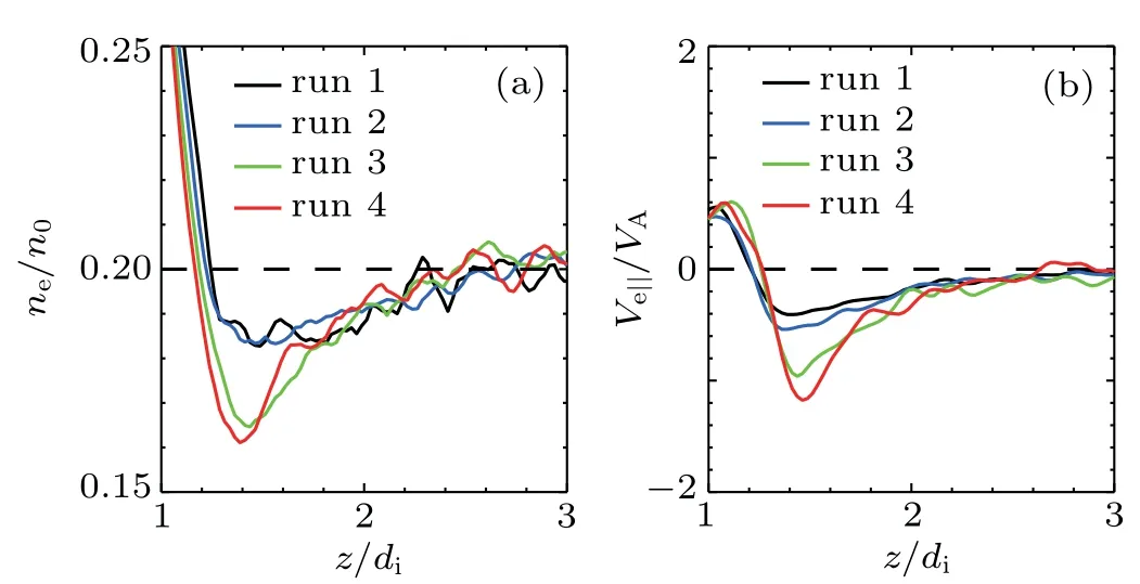
Fig. 9. The profile of (a) the electron number density ne and (b) the parallel electron bulk flow velocity Ve‖ along the line at x=22.5di parallel to the z axis for run 1 at Ωi0t =21.25(black solid lines),run 2 at Ωi0t=19(blue solid lines),run 3 at Ωi0t=17.5(green solid lines),and run 4 at Ωi0t =16.5 (red solid lines). The black dashed line in panel(a)indicates the initial electron density in the inflow region nb=0.2n0.The black dashed line in panel(b)denotes the value Ve‖/vA=0.
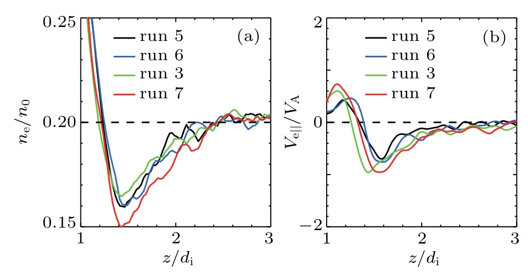
Fig. 10. The profile of (a) the electron number density ne and (b) the parallel electron bulk flow velocity Ve‖ along the line at x = 22.5di parallel to the z axis for run 5 at Ωi0t = 21 (black solid lines), run 6 at Ωi0t =19.5 (blue solid lines), run 3 at Ωi0t =17.5 (green solid lines), and run 7 at Ωi0t =16.75 (red solid lines). The black dashed line in panel (a) indicates the initial electron density in the inflow region nb =0.2n0. The black dashed line in panel(b) denotes the value Ve‖/vA=0.
Figure 11(a)shows the parallel electrostatic potential Φ‖along the separatrix for run 1 at Ωi0t=21.25,run 2 at Ωi0t=19, run 3 at Ωi0t =17.5, and run 4 at Ωi0t =16.5. At these times, all runs obtain the maximum reconnection rate. It can be found that with the increase in the mass ratio, the parallel electrostatic potential Φ‖along the separatrix is enhanced.Figure 11(b) shows the Φ‖along the separatrix for run 5 at Ωi0t=21,run 6 at Ωi0t=19.5,run 3 at Ωi0t=17.5,and run 7 at Ωi0t=16.75.At these times,all runs obtain the maximum reconnection rate. With the decrease in light speed,the parallel electrostatic potential in the separatrix region also tends to be more salient.mirror force become more and more important for electron acceleration. If we compare these two mechanisms,the parallel electric field force is more important for electron acceleration;however, the magnetic mirror force cannot be neglected either.In Fig.7(c),the difference between the electron flow convective derivation∫ll0me(V ·?)V‖dl (black solid line)and the sum of the parallel electric field force and the magnetic mirror force -∫dl (black dashed line) comes from the nonadiabatic motion of some electrons, which cannot be described by the guiding center theory. This difference becomes much more obvious in the electron diffusion region(Ls<3.0di, indicated by the blue solid line in Fig.7), where the electron motion is decoupled with the local magnetic field and the guiding center theory fails.
We also investigate the influences of the ion-to-electron mass ratio and light speed on the electron depletion layer and parallel electric field in the separatrix region. Figure 8(a)plots the time evolution of the reconnected flux ψ for runs 1-4. A group of runs have the same light speed but different ion-toelectron mass ratios. Obviously,the ion-to-electron mass ratio does not change the reconnection rate,although reconnection occurs earlier with the increase in the mass ratio. Figure 8(b)plots the time evolution of the reconnected flux ψ for runs 3 and 5-7. A group of cases have the same ion-to-electron mass ratio but different light speeds.With the decrease in light speed, reconnection occurs earlier, but the reconnection rate hardly changes.
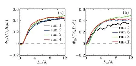
Fig.11. (a)The parallel electrostatic potential Φ‖ along the separatrix for run 1 at Ωi0t=21.25(black solid line),run 2 at Ωi0t=19(blue solid line), run 3 at Ωi0t =17.5(green solid line), and run 4 at Ωi0t =16.5(red solid line). (b) The parallel electrostatic potential Φ‖ along the separatrix for run 5 at Ωi0t =21 (red solid line), run 6 at Ωi0t =19.5(blue solid line), run 3 at Ωi0t =17.5 (green solid line), and run 7 at Ωi0t =16.75 (red solid line). In the figure, the black dashed lines denote the value Φ‖/vAB0di=0.
4. Summary and discussion
In this paper, with 2D PIC simulations, we studied the properties of the electron depletion layer and parallel electric field in the separatrix region during anti-parallel reconnection.At first,the parallel electric field pointing away from the X line is formed in the separatrix region,and then the parallel electric field pointing toward the X line is developed in the separatrix region around the X line. Both the increase in the ion-to electron mass ratio and decrease in light speed make the electron depletion layer and parallel electric field more salient in the separatrix region.
Satellite observations have already revealed the existence of the parallel electric field in the separatrix region during magnetic reconnection.[17,45,46]Both observations and our simulations have shown that in addition to the reconnection electric field induced around the X line, there still exists the parallel electric field in the separatrix region,which may play an important role in electron acceleration during magnetic reconnection. How the parallel electric field in the separatrix region will act on electron acceleration during magnetic reconnection is a direction for our future work.

- Chinese Physics B的其它文章
- Topological magnon insulator with Dzyaloshinskii-Moriya interaction under the irradiation of light?
- Wavelength dependence of intrinsic detection efficiency of NbN superconducting nanowire single-photon detector?
- Artificial solid electrolyte interphase based on polyacrylonitrile for homogenous and dendrite-free deposition of lithium metal?
- Effects of CeO2 and nano-ZrO2 agents on the crystallization behavior and mechanism of CaO-Al2O3-MgO-SiO2-based glass ceramics?
- Modulation of magnetic and electrical properties of bilayer graphene quantum dots using rotational stacking faults?
- Thermal conductivity characterization of ultra-thin silicon film using the ultra-fast transient hot strip method?