
Lateral characteristics improvements of DBR laser diode with tapered Bragg grating
2022-09-24 08:00:10QiQiWang王琦琦LiXu徐莉JieFan范杰HaiZhuWang王海珠andXiaoHuiMa馬曉輝
Chinese Physics B 2022年9期
Qi-Qi Wang(王琦琦), Li Xu(徐莉), Jie Fan(范杰), Hai-Zhu Wang(王海珠), and Xiao-Hui Ma(馬曉輝)
State Key Laboratory of High-Power Laser Diodes,Changchun University of Science and Technology,Changchun 130022,China
Keywords: tapered Bragg grating,lateral beam,semiconductor laser
1. Introduction
Semiconductor laser diodes are widely used in medical,free-space communication, and detection due to their excellent properties.[1-3]However, with the development of technology, their outstanding lateral mode power outputs are required. Although the traditional narrow ridge lasers can possess the excellent lateral mode characteristics by narrowing the ridge width,the further enhancement of their output power values is limited.[4]The tapered laser diode integrates master oscillator power amplifier to amplify power.[5]However,most of tapered laser diodes are accompanied by complex process and non-linear effects.[6]Based on increasing the loss difference between fundamental mode and high-order modes,broad area semiconductor lasers(BALs)can achieve the preeminent lateral mode profile by introducing microstructure. In 2016,Ronget al. reported a fishbone-shape microstructure based on BAL.[7]The divergence was reduced to 15.8°for 95%power,and the device can achieve a 330 mW power at 1.5 A.In 2018,Miahet al. reported a ridge-waveguide edge-emitting laser with triangular-shaped corrugations on both sides of ridge.[8]The lasers provided single-lateral mode emission across a wide current range and achieved almost 400 mW of power at 1 A. In 2020 , Wanget al. presented an approach to flexibly tailoring the optical losses of different-order lateral modes by etching micro-holes on the laser mesa with controlled position and numbers.[9]The lateral divergence angle was reduced to 2.2°.
The spectral characteristics of traditional lasers are usually characterized by large linewidth and low side mode suppression ratio. Owing to the integration of Bragg grating,distributed Bragg reflector (DBR) laser can achieve narrow linewidth output in comparison with traditional laser.[10]In 2019,Xieet al.designed a DBR laser with the nineteenth order grating to achieve 0.45-nm linewidth.[11]The full width at half maximum (FWHM) linewidth of the DBR laser was narrowed by 65%in comparison with that of the conventional laser. In 2019,Chenet al. designed a DBR laser with output power of 9.9 mW and ultra-narrow linewidth of 70 kHz.[12]In 2020, Zhouet al. designed forty-nine-order Bragg grating to achieve 3-nm linewidth of FWHM.[13]But few previous studies of DBR laser diodes focused on the improvement of lateral mode emission.
In this work, the DBR laser diode with tapered grating(TDBR-LD) is designed. The tapered grating provides loss difference among the lateral modes due to the variation of the lateral width. Therefore, the TDBR-LD can suppress the high-order lateral modes and achieve preeminent lateral beam characteristics. In addition,the TDBR-LD possesses superior spectra characteristics.
2. Device design and fabrication
2.1. Device structure
Figure 1 shows the three-dimensional (3D) image of TDBR-LD.The device consists of a ridge waveguide and the tapered grating. The width of ridge is represented byWRand the length of ridge is denoted asLR. The tapered grating is used as a reflector on the rear facet. The width of tapered grating close to the ridge waveguide is represented byWG,and the width gradually changes fromWGtoWRalong the longitudinal direction. The length of grating is referred to asLG. The vertical structure of wafer is grown on N-GaAs substrate.[14,15]A 10.4-nm-thick In0.27Ga0.82As/GaAs single quantum well is placed as active region into 400-nm thick waveguide. The Al0.3Ga0.7As is grown as the cladding, with the n-dopant being silicon and the p-dopant zinc.A 130-nm-thick deep doping cap layer strengthens the carrier injection.
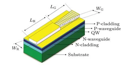
Fig.1. The 3D image of device containing vertical materials and parameters of structure.
2.2. Design of device
An appropriately designed Bragg grating can provide wavelength feedback. Thus, the spectra of BAL with grating can be modified by perturbing the effective refractive index,[16]specifically they are related by the following equation:

wheremandmgare the integers,λis the Bragg wavelength,dpis the grating period,dgis the distance between the grooves,neff,aveandneff,gare the average effective refractive index of the laser waveguide and the effective refractive index of the material in the groove,respectively. Based on Eq.(2),a grating with a period of 7 μm and a duty cycle of 0.6 can be designed.
The reflectivity of tapered grating with 350μm in length is simulated using Rsoft. Figure 2 shows the reflectivity of tapered grating varying withWG.WhenWGis 40μm,the grating is straight grating actually,and its reflectivity is 62.32%. With the decrease ofWG,the reflectivity of grating decreases gradually. And the reflectivity decreases to 39.23% whenWGdecreases to 16μm. Owing to the variation of the lateral layout,in the grating there appears the leak of optical energy. Photons transferring through tapered grating will experience additional dispersion losses. The reflectivity of tapered grating is lower than that of straight grating under the same condition. The inset of Fig.2 shows the relationship of spectra with etch depth.The reflectivity and FWHM is influenced by depth of grating. Reflectivity increases with etch depth increasing. They present hyperbolic tangent functions. But excessive depth will increase loss, even cause the optical leakage from waveguide layer.
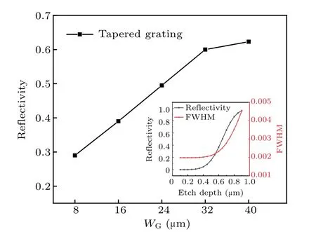
Fig.2. Reflectivity of tapered grating varying with WG,with inset showing relationship between reflectivity and etching depth.
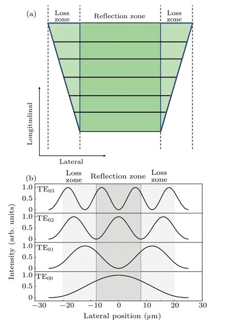
Fig.3. (a)Layout of tapered grating and(b)the one-dimensional field energy of 40-μm ridge for each order lateral mode.
The number of high-order lateral modes increases with ridge width increasing. Meanwhile, the high-order modes come to compete with the fundament mode for optical power.[17]Figure 3 displays the layout of the tapered grating,and one-dimensional(1D)field energy of lateral mode. Based on the lateral position, the tapered grating can be defined in three zones. Area in the center is defined as“reflection zone”,and both of side area are defined as“loss zone”.The schematic of tapered grating is shown in Fig. 3(a). Because the tapered grating has different longitudinal lengths along the longitudinal direction,the feedback effect of the optical field will vary with the lateral position. Figure 3(b) shows the lateral-cross section energy of each order lateral mode. For the fundament transverse electric mode (TE00), the intensity of lateral beam has an approximate Gaussian distribution. In the first transverse electric mode(TE01)there exist two peaks in the lateral field. The number of peaks increases with the order of mode increasing. Inside the cavity, the competition of lateral mode results in the under-performing output characteristics. Therefore, the layout of tapered grating is beneficial to the lateral mode improvement.
The effects of tapered grating on the transmission of optical fields for different order lateral modes are simulated. The results are shown in Fig.4.The transmission distribution of tapered grating for the TE00is displayed in Fig.4(a). The TE00is mainly affected by the reflection zone,since the energy concentrates in the center along the lateral direction, so that the tapered grating can provide excellent optical feedback for the TE00. It can be seen from the distribution in Fig. 4(b) that the loss zone guides optical energy leakage, resulting in the increase of mode loss. The major energy is consumed during the transmission. Similarly, figure 4(c) shows the transmission distribution of taper grating for the third transverse electric mode(TE03). The energy of reflection zone is reflected by the adjective grating pairs,also both side-lobes of TE03suffer more loss than center-lobes.
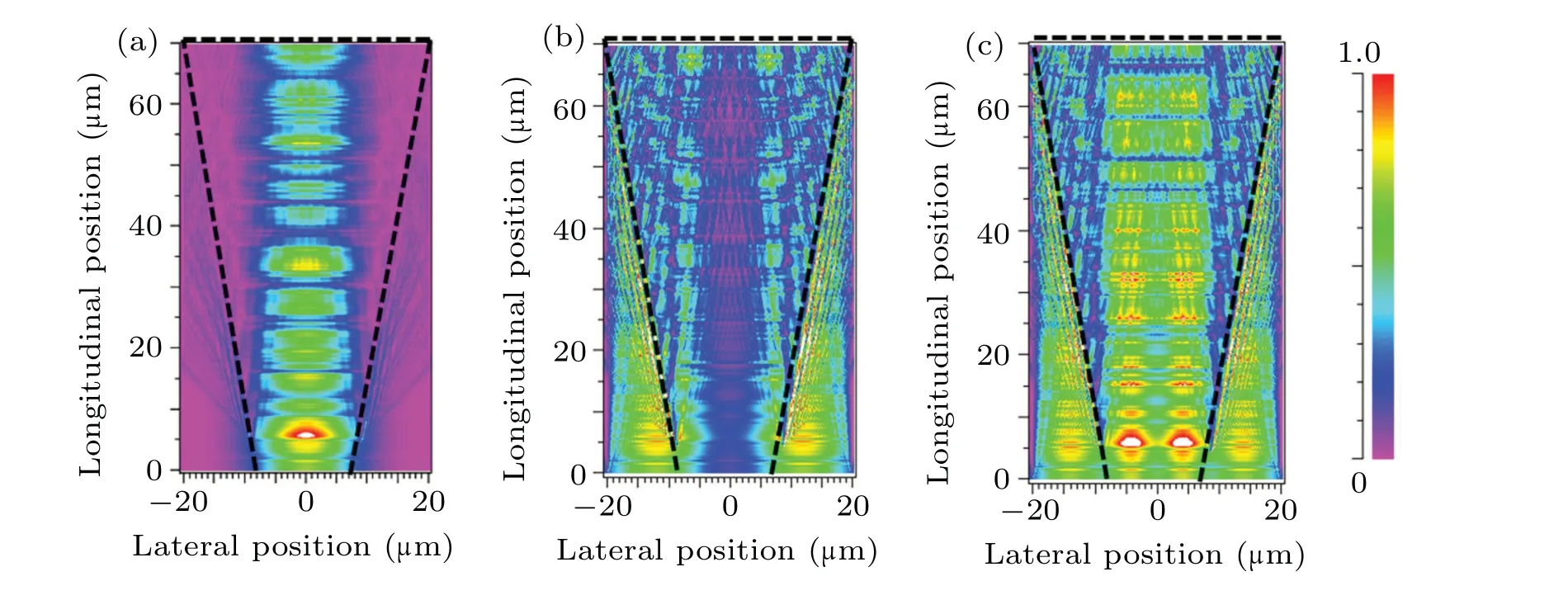
Fig.4. Transmission distribution of tapered grating for(a)TE00,(b)TE01,and(c)TE03.
Further, the influence of a tapered grating with a length of 350μm on the lateral modes is simulated. Figure 5 shows the influence ofWGon the reflectivity of each lateral mode.WhenWGis 40 μm, the tapered grating is simplified into a straight grating, and there is no loss zone. The reflectivity of each lateral mode is almost the same, and its value is close to 0.63. With the decrease ofWG, the loss zone appears and then expands. The reflectivity gradually decreases as theWGshortens to 24 μm. There is a distinct variation for each of higher-order modes. WhenWGis 16 μm, the reflectivity for the lateral fundament mode further declines to 0.54811. And the reflectivity for the TE01further down to 0.119. The reflectivity presents that the loss zone filtrates high-order modes,especially for TE01. For TE00,the optical energy concentrates in the central area, and optical feedback occurs mainly in reflection zone. Contrary to TE00,major optical energy of TE01is transmitted into the loss zone and suffers additional scattering. More energy of the second transverse electric mode(TE02) and TE03are affected by the reflection zone than that of TE01. Therefore, a large difference in reflectivity between the TE00mode and the TE01mode is formed. The loss zone further expands whenWGshortens to 8μm,and the reflectivity of each lateral mode further decreases. In conclusion, the tapered grating enables the modulating of lateral modes.
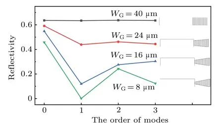
Fig.5. Influence of WG on reflectivity of each lateral mode.
2.3. Fabrication of device
The TDBR-LD and straight distribution Bragg reflector laser diode (SDBR-LD) were fabricated on the same wafer which is grown by MOCVD. First, the ridge waveguide and tapered grating were patterned by UV lithography,and etched by inductively coupled plasma (ICP) etching with a depth of 600 nm.WR,LR, andWGare 40 μm, 1350 μm, and 16 μm respectively. Then 300-nm-thick SiO2was deposited on the surfaces of devices by plasma enhanced chemical vapor deposition(PECVD)as electrical insulation layers. The contact windows were etched by buffered oxide etch(BOE).After being thinned and polished,the Ni-Au/Ge-Ni-Au contact layer was grown on the backside of wafer. Laser devices have been cleaved and packaged with C-mount. Figure 6 shows the microscope diagram of the packaged device. The devices were mounted p-side up on the copper heat sink with metal indium without facet coating. Gold wires were introduced on the surface of the device for current injection. The devices operate with a water temperature control laser module which is maintained steadily at room temperature(20°C)for testing.
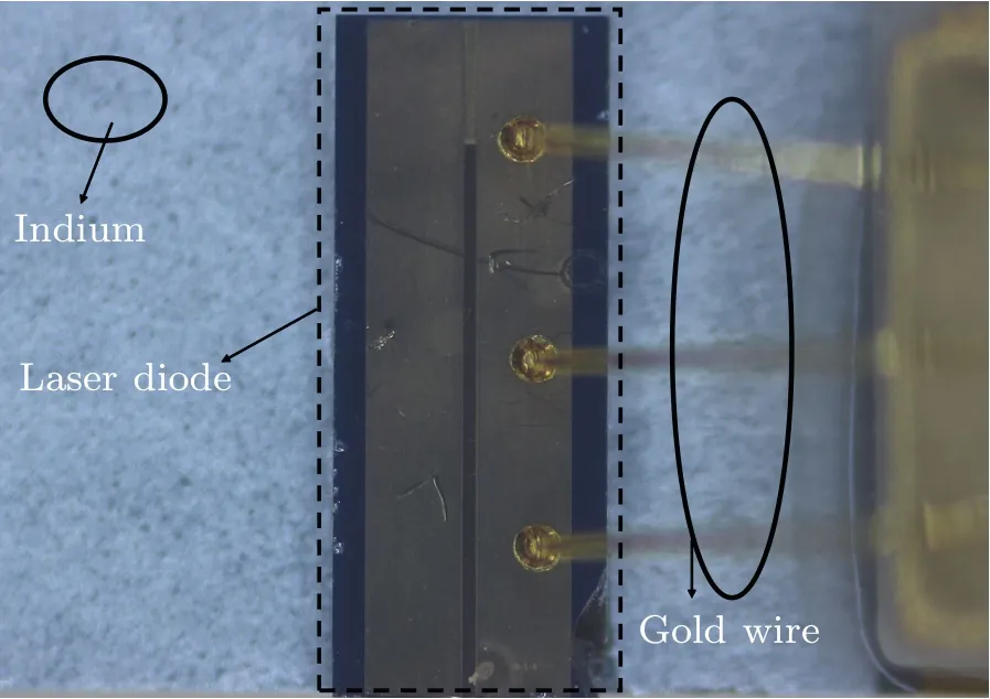
Fig.6. Microscope diagram of TDBR-LD device.
3. Results and discussion
3.1. Far-field characteristics
The far-field characteristics of TDBR-LD and SDBR-LD are investigated. The Cinogy CinCam CMOS camera is used to capture the far-field spot, and the RayCi-Lite software is used to measure the spot. Figure 7 presents the far-field spot and the corresponding lateral profile. The far-field spot and lateral profile of SDBR-LD at 0.2 A are shown in Fig. 7(a),from which it can be seen that the far-field spot has three lobes with different intensities. As the current increases to 0.9 A, the far-field spot of SDBR-LD still possesses three asymmetrical spots as shown in Fig. 7(b). The phenomenon might be caused by asymmetrical carrier injection. As shown in Fig. 7(c), the SDBR-LD has worse lateral mode output at 1.5 A.Figures 7(d)and 7(e)show the characteristics of TDBRLD at 0.2 A and 0.9 A respectively.Compared with the lobe of SDBR-LD,the lobe of TDBR-LD decreases to one,and more output energy concentrates in the center. Figure 7(f)presents the deterioration of laser at 1.5 A.The spot has two lobes in the lateral direction. As the current increases, high-order modes may dominate the cavity due to the gain difference, and the lateral characteristics of the device will deteriorate. In conclusion,the tapered grating can effectively suppress the highorder lateral modes, thus improving the lateral beam characteristics of the TDBR-LD.
Meanwhile,figure 8 shows the lateral far-field divergence angle of TDBR-LD and SDBR-LD at 1 A.The SDBR-LD has several side-lobes and TDBR-LD is bare of side-lobes. The FWHM of SDBR-LD is 6.26°and that of TDBR-LD is 5.23°.Comparing with SDBR-LD,the lateral far-field divergence of TDBR-LD is improved by approximately 17%. The characterizations of far-field further reveal that the TDBR-LD can effectively suppress the side-lobes in the lateral far-field and improve the lateral divergence obviously. The results and improvement in the field of lateral profiles are meaningful.

Fig.7. Far-field spot of SDBR-LD at injection current of(a)0.2 A,(b)0.9 A,and(c)1.5 A;far-field spot of TDBR-LD at injection current of(d)0.2 A,(e)0.9 A,and(f)1.5 A.
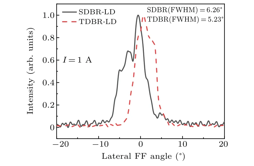
Fig. 8. Lateral far-field divergence angle at injection current of 1 A for DBRL and TDBRL.
3.2. Spectrum property
By means of fiber coupling, the Ocean Optics HR4000 is used to measure the spectra of devices. Figure 9 shows the peak wavelengths and FWHM linewidths of the devices in an injection current range from 0.2 A to 1 A.The insets of Fig.9 show the spectrum of SDBR-LD and also the spectrum of TDBR-LD at 0.2 A.With the increase of current,the peak wavelength of TDBR-LD shows the redshift from 1060.9 nm to 1066.2 nm,while the peak wavelength of SDBR-LD shifts from 1061.7 nm to 1068.9 nm. The tapered grating has a loss zone to lead optical leakage,and less photons back to resonant cavity thought grating. Thus,it may reduce the heat accumulation inside the cavity.
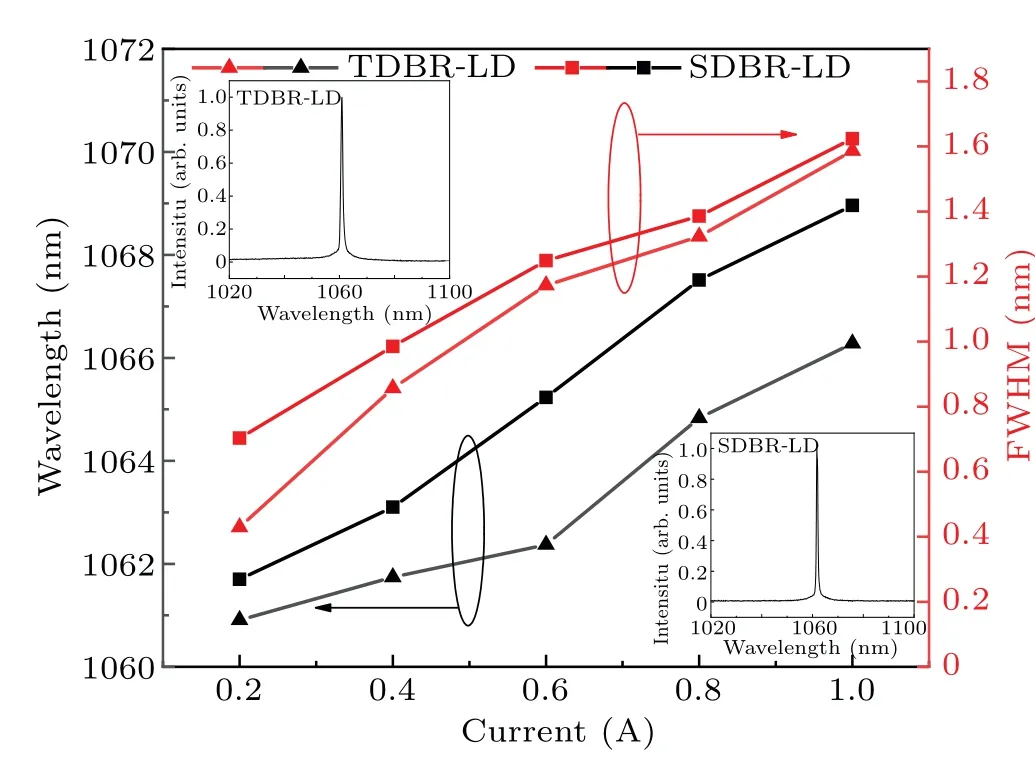
Fig. 9. Peak wavelengths (black) and FWHMs (red) of SDBR-LD and TDBR-LD,with insets showing spectra of TDBR-LD(left)and SDBR-LD(right).
Another surprising aspect of the data is the decline of linewidth. At 0.2 A, the FWHM linewidth of TDBR-LD is 0.429 nm and that of SDBR-LD is 0.703 nm, each with a reduction of 39%. A possible explanation for this might be that the lateral mode competition suppresses the high-order modes,thereby improving the stray modes partially.With the increase of current, the high-order lateral modes might dominate, and the linewidth difference decreases gradually. As shown in Fig. 9, the difference in linewidth between TDBR-LD and SDBR-LD is 0.274 nm at 0.2 A and it declines to 0.037 nm at 1 A.
3.3. The P-I-V characteristics
The THORLABS S146C Power Meter Head and the THORLABS PM400 Energy Meter Console are used to measure the output power of the laser. The power-current-voltage(P-I-V)curves of devices are diplayed in Fig.10.For the voltage curves,both devices exhibit similar electrical characteristics. The inset shows theP-Icurves near the threshold current,which indicate that the threshold current of TDBR-LD is 160 mA and the threshold current of SDBR-LD is 130 mA.At the lower injection current,the cavity might generate extra loss of high-order lateral modes due to the tapered grating,so that the threshold current increases with the decrease of photons in the resonant process. The slope efficiency of TDBR-LD decreases from 0.398 W/A of SDBR-LD to 0.382 W/A.The difference in slope efficiency between TDBR-LD and SDBR-LD may be influenced by tapered grating. The tapered grating has lower reflection than straight grating,which will lead the cavity facet loss to increase,and therefore the slope efficiency of TDBR-LD decreases. In addition, the lateral mode competition of TDBR-LD is reduced under the modulation of tapered grating. And the reduction of lateral mode competition can improve the output power.[17,18]Under the action of the above two factors, the maximum power of TDBR-LD is improved slightly. It can also be seen from Fig. 10 that for the TDBRLD there occurs power saturation and 473-mW output power is achieved,when the injection current is 1.4 A,while for the SDBR-LD there appears power saturation and 466.6-mW output power is obtained when the injection current is 1.3 A.
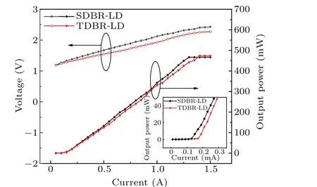
Fig. 10. The P-I-V curves of packaging component at room temperature,with inset showing P-I curves near the threshold.
4. Conclusions
In this work, a DBR laser diode with tapered grating is designed. By increasing the gain threshold of high-order lateral modes,the tapered grating suppresses the competition between the fundamental lateral mode and the high-order lateral modes.The lateral mode characteristics of TDBR-LD is effectively improved, and TDBR-LD realized a single-lobe output in a range below 0.9 A. Comparing with SDBR-LD, the lateral far-field divergence of TDBR-LD decreases from 6.26°to 5.23°at 1 A. Meanwhile, benefiting from the improvement of lateral mode characteristics, the TDBR-LD achieves superior spectral characteristics in comparison with SDBR-LD,the maximum output power of TDBR-LD is enhanced from 466 mW to 473 mW.
Acknowledgement
Project supported by the Science and Technology Development Plan of Jilin Province, China (Grant Nos.20210201030GX and 20210201089GX).
- Chinese Physics B的其它文章
- Erratum to“Accurate determination of film thickness by low-angle x-ray reflection”
- Anionic redox reaction mechanism in Na-ion batteries
- X-ray phase-sensitive microscope imaging with a grating interferometer: Theory and simulation
- Regulation of the intermittent release of giant unilamellar vesicles under osmotic pressure
- Bioinspired tactile perception platform with information encryption function
- Quantum oscillations in a hexagonal boron nitride-supported single crystalline InSb nanosheet