基于羅氏線圈電流互感器的等傳變距離保護(hù)
2023-03-11 09:39:50李寶偉王志偉文明浩
電工技術(shù)學(xué)報(bào) 2023年5期
李寶偉 石 欣 王志偉 文明浩 張 旭
基于羅氏線圈電流互感器的等傳變距離保護(hù)
李寶偉1,2石 欣2王志偉2文明浩1張 旭2
(1.強(qiáng)電磁工程與新技術(shù)國家重點(diǎn)實(shí)驗(yàn)室(華中科技大學(xué)) 武漢 430074 2.許繼電氣股份有限公司 許昌 461000)
羅氏線圈電流互感器中的積分器會(huì)放大暫態(tài)傳變誤差,可能導(dǎo)致保護(hù)誤動(dòng)作。該文提出直接采用羅氏線圈微分信號(hào)輸出進(jìn)行保護(hù)計(jì)算的改進(jìn)思路,并以距離保護(hù)為例,提出一種基于羅氏線圈電流互感器的等傳變距離保護(hù)方法。該方法中,保護(hù)電流直接采用羅氏線圈輸出的電流微分信號(hào),消除積分器引入的暫態(tài)傳變誤差,并通過虛擬數(shù)字傳變解決電壓與電流微分信號(hào)傳變不一致問題。仿真和試驗(yàn)結(jié)果表明,所提出的等傳變距離保護(hù)方法動(dòng)作速度快,受系統(tǒng)中高頻暫態(tài)信號(hào)影響較小,性能優(yōu)于現(xiàn)有距離保護(hù)方法。
羅氏線圈 積分器 距離保護(hù) 虛擬羅氏線圈 等傳變
0 引言
羅氏線圈型電流互感器由于其具有動(dòng)態(tài)測(cè)量范圍大、無磁飽和現(xiàn)象、頻帶響應(yīng)范圍寬、絕緣結(jié)構(gòu)簡單等諸多優(yōu)點(diǎn),已在電力系統(tǒng)中得到了廣泛的工程應(yīng)用[1-12]。由于羅氏線圈輸出信號(hào)與被測(cè)電流的微分成正比,羅氏線圈電流互感器通常配置積分器,以恢復(fù)被測(cè)的電流信號(hào)[13-15]。
工程應(yīng)用情況表明,積分器會(huì)放大羅氏線圈的暫態(tài)傳變誤差和模數(shù)轉(zhuǎn)換誤差,可能造成電流傳變嚴(yán)重失真,導(dǎo)致繼電保護(hù)不正確動(dòng)作。文獻(xiàn)[16]闡述了羅氏線圈電流互感器異常輸出導(dǎo)致繼電保護(hù)誤動(dòng)的案例。在斷路器合閘時(shí),羅氏線圈輸出信號(hào)中出現(xiàn)了一個(gè)采樣點(diǎn)的異常數(shù)據(jù),該異常數(shù)據(jù)經(jīng)積分器處理后,輸出了峰值達(dá)5倍額定電流,持續(xù)時(shí)間長達(dá)70ms的異常數(shù)據(jù),導(dǎo)致保護(hù)誤動(dòng)作。文獻(xiàn)[17]分析了斷路器合閘操作時(shí)羅氏線圈電流互感器異常輸出的機(jī)理。系統(tǒng)運(yùn)行操作會(huì)伴隨產(chǎn)生高頻暫態(tài)分量,在羅氏線圈微分傳變特性的作用下,高頻暫態(tài)分量被進(jìn)一步放大,羅氏線圈在高頻信號(hào)激勵(lì)下會(huì)產(chǎn)生附加衰減直流分量,頻率混疊也可能產(chǎn)生附加直流分量,附加的直流分量經(jīng)積分器處理后,將在輸出信號(hào)中疊加持續(xù)時(shí)間較長的動(dòng)態(tài)附加分量,可能導(dǎo)致電流傳變嚴(yán)重失真。
研究者提出了多種羅氏線圈電流互感器異常輸出的優(yōu)化和檢測(cè)方法,但在故障暫態(tài)過程中均受到限制,并不能完全解決保護(hù)誤動(dòng)的問題。文獻(xiàn)[18]指出電子式電流互感器存在一定程度的頻率混疊,并提出了優(yōu)化抗混疊濾波器和提高采樣率的改進(jìn)方法,但受羅氏線圈自身傳變特性影響產(chǎn)生的衰減直流分量無法被消除[19],仍可能造成傳變嚴(yán)重失真。文獻(xiàn)[20]提出了基于直流負(fù)反饋原理的改進(jìn)數(shù)字積分算法優(yōu)化直流響應(yīng)的方法,但該方法計(jì)算量大,且反饋環(huán)節(jié)會(huì)造成輸出延時(shí)增加,影響保護(hù)動(dòng)作速度。文獻(xiàn)[21]提出利用電流同源數(shù)據(jù)特征比對(duì)的異常數(shù)據(jù)識(shí)別方法,該方法無法解決羅氏線圈自身傳變特性造成的異常輸出問題。文獻(xiàn)[22]提出通過羅氏線圈和測(cè)量線圈輸出信號(hào)對(duì)比判別采樣數(shù)據(jù)異常的方法,但由于測(cè)量線圈無法正常傳變故障電流,所以該方法應(yīng)用也受到限制。
本文提出了直接采用羅氏線圈微分信號(hào)輸出進(jìn)行保護(hù)計(jì)算的改進(jìn)思路,并以距離保護(hù)為例,提出基于羅氏線圈微分信號(hào)輸出的等傳變距離保護(hù)方法,為其他類型線路保護(hù)的研究提供了借鑒。
1 基本原理
距離保護(hù)新方法直接采用羅氏線圈輸出的電流微分信號(hào),但電流微分信號(hào)無法直接與電壓信號(hào)進(jìn)行保護(hù)計(jì)算。根據(jù)輸電線路等傳變理論[23-25],線路沿線電壓和電流經(jīng)過相同的線性傳變后,其相互關(guān)系仍滿足原輸電線路分布參數(shù)模型。因此,通過構(gòu)造虛擬羅氏線圈數(shù)字傳變環(huán)節(jié),對(duì)電壓信號(hào)進(jìn)行與羅氏線圈傳變特性相同的數(shù)字傳變處理,使得距離保護(hù)所使用的電壓、電流信號(hào)經(jīng)過相同的傳變環(huán)節(jié),采用R-L模型解微分方程算法計(jì)算故障位置,判別保護(hù)是否動(dòng)作。
傳統(tǒng)距離保護(hù)的數(shù)據(jù)傳變環(huán)節(jié)如圖1所示,羅氏線圈輸出微分信號(hào)的積分處理環(huán)節(jié)配置在合并單元中[17]。
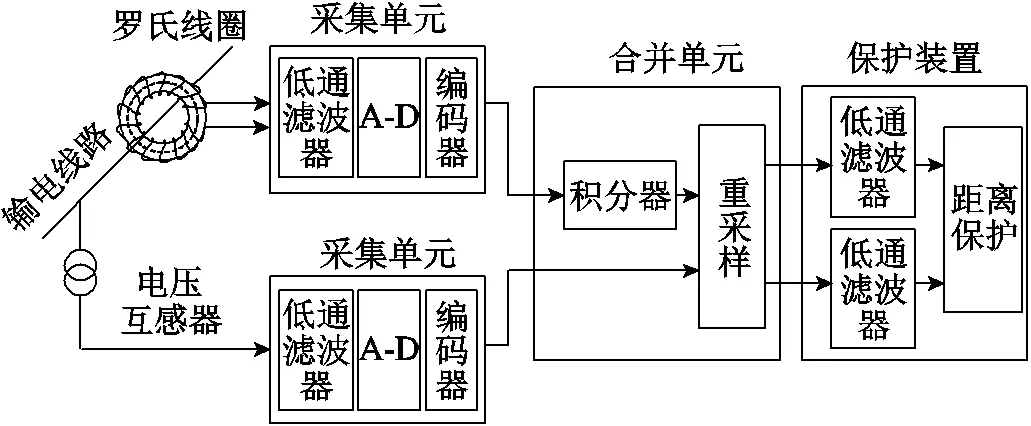
圖1 傳統(tǒng)距離保護(hù)數(shù)據(jù)傳變環(huán)節(jié)
新方法數(shù)據(jù)傳變環(huán)節(jié)如圖2所示,取消合并單元中的積分環(huán)節(jié),在保護(hù)裝置中電壓的傳變環(huán)節(jié)增加虛擬數(shù)字羅氏線圈。
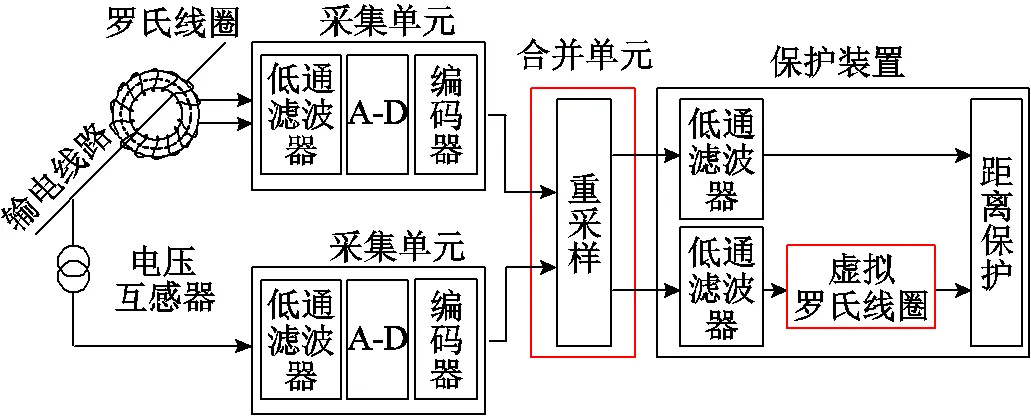
圖2 新方法數(shù)據(jù)傳變環(huán)節(jié)
基于羅氏線圈電流互感器的等傳變距離保護(hù)原理主要包括虛擬羅氏線圈數(shù)字傳變方法、R-L模型解微分方程算法應(yīng)用、故障點(diǎn)電壓重構(gòu)和保護(hù)動(dòng)作判據(jù)。
1.1 虛擬羅氏線圈數(shù)字傳變方法
羅氏線圈等效電路如圖3所示,為羅氏線圈互感,()為一次電流,()為線圈的感應(yīng)電動(dòng)勢(shì),S為線圈內(nèi)阻,為線圈自感,0為線圈匝間電容,a為負(fù)載電阻,()為電壓輸出信號(hào)。
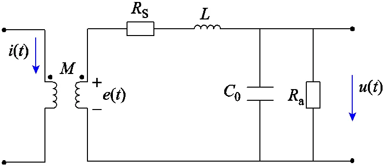
圖3 羅氏線圈等效電路
Fig.3 Equivalent circuit of Rogowski coil CT
根據(jù)電感、電容元件的暫態(tài)等效電路[23],可進(jìn)一步得到羅氏線圈的暫態(tài)等效電路,如圖4所示。圖4中,1(),2(),3()分別為暫態(tài)等效電路中的三個(gè)節(jié)點(diǎn)電壓。i(-Δ),i0(-Δ)分別為線圈自感和匝間電容的等效電流源,R=2/Δ,R0=Δ/20。
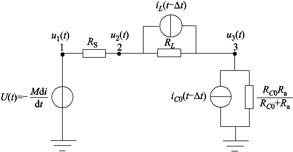
圖4 羅氏線圈暫態(tài)等效電路
根據(jù)節(jié)點(diǎn)電壓方程,可得
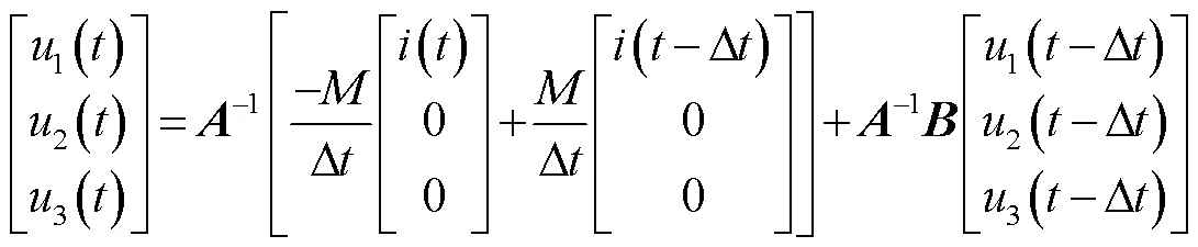
其中
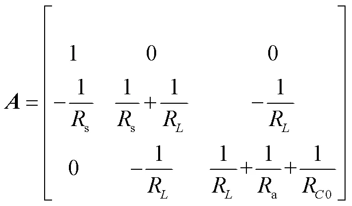
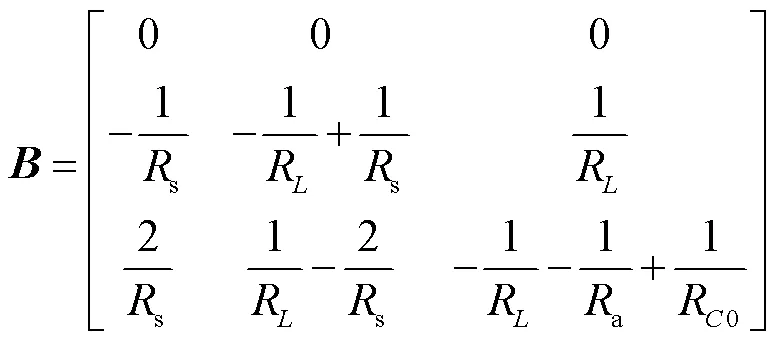
式中,3()為羅氏線圈輸入電流()的輸出信號(hào)。因此虛擬羅氏線圈數(shù)字傳變方法為
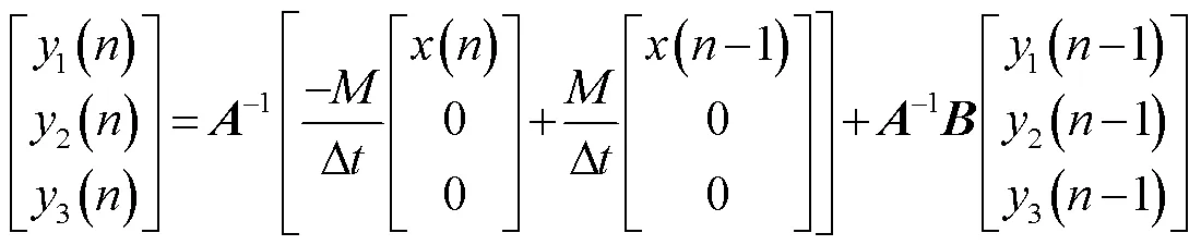
式中,()為輸入數(shù)據(jù)的第個(gè)采樣點(diǎn)的值;1(-1)為輸出數(shù)據(jù)第-1個(gè)采樣點(diǎn)的計(jì)算值。
1.2 R-L模型解微分方程算法應(yīng)用
當(dāng)輸電線路發(fā)生故障時(shí),故障信號(hào)中高頻分量主要由線路對(duì)地分布電容引起,通過設(shè)置合適的數(shù)字低通濾波器,濾除高頻分量,可降低線路分布電容的影響。不考慮分布電容影響的輸電線路模型可以等效為R-L模型,以線路發(fā)生單相故障為例,說明采用R-L模型解微分方程計(jì)算故障位置的方法。
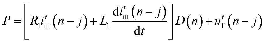
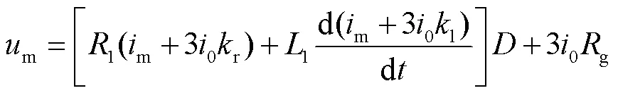
對(duì)于單相接地故障,保護(hù)安裝處的測(cè)量電壓和測(cè)量電流滿足
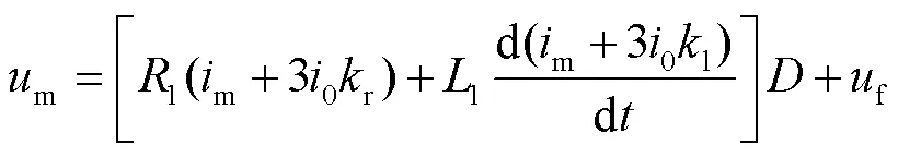
式中,r=(0-1)/(31);l=(0-1)/(31);m和m分別為保護(hù)安裝處故障相電壓和電流;30為保護(hù)安裝處的零序電流;f為故障點(diǎn)電壓;1、0、1、0分別為單位長度線路的正序電阻、零序電阻、正序電感、零序電感;為故障距保護(hù)安裝處的距離。
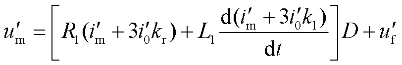
式(5)中保護(hù)電流、保護(hù)安裝處電壓、故障點(diǎn)電壓經(jīng)過相同的傳變環(huán)節(jié)后,方程仍成立,有
1.3 故障點(diǎn)電壓重構(gòu)
在故障發(fā)生初期,經(jīng)虛擬羅氏線圈數(shù)字傳變處理的保護(hù)安裝處電壓會(huì)存在短時(shí)暫態(tài)傳變過程,如故障點(diǎn)電壓忽略此暫態(tài)傳變過程,將會(huì)產(chǎn)生一定的誤差。因此對(duì)故障點(diǎn)電壓進(jìn)行重構(gòu),并進(jìn)行虛擬數(shù)字傳變處理,使其與保護(hù)安裝處電壓保持相同的暫態(tài)傳變過程,減小故障初期計(jì)算故障,加快故障計(jì)算收斂至穩(wěn)定的速度。采用與文獻(xiàn)[26]類似的辦法,對(duì)故障點(diǎn)電壓進(jìn)行重構(gòu)處理。故障點(diǎn)電壓可表示為
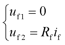
式中,f為故障點(diǎn)電壓,由f1和f2兩部分組成。故障前,f1和f2可以表示為
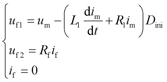
故障后,f1和f2可以表示為
式中,1和1分別為單位長度的正序電感和正序電阻;ini為故障位置到保護(hù)安裝處的距離初始值;f為過渡電阻;f在故障發(fā)生前為零,故障發(fā)生后為故障電流。工程應(yīng)用中,故障點(diǎn)電流通常采用保護(hù)安裝處的零序電流替代[26]。
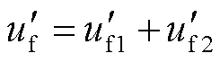
式(6)中,經(jīng)虛擬羅氏線圈進(jìn)行傳變環(huán)節(jié)補(bǔ)償后的故障點(diǎn)電壓可表示為
正常運(yùn)行時(shí),輸電線路沿線電壓降落較小,由于故障位置未知,為求解式(6),可使用沿線某一點(diǎn)電壓來代替uf1。為進(jìn)一步減小距離保護(hù)的測(cè)距誤差,采用故障點(diǎn)位置迭代逼近的方法。由式(6)和式(10)可知,和f為未知量,取故障后一個(gè)時(shí)間段(例如5ms)的多個(gè)采樣時(shí)刻數(shù)據(jù),建立方程組,通過最小二乘法即可求解故障點(diǎn)到保護(hù)安裝處的距離。
故障位置計(jì)算的主要步驟如下:
(1)假設(shè)故障點(diǎn)位于被保護(hù)線路的中點(diǎn)。
(2)保護(hù)電壓經(jīng)虛擬羅氏線圈,補(bǔ)償傳變差異。
(3)根據(jù)故障點(diǎn)的位置對(duì)故障點(diǎn)電壓進(jìn)行重構(gòu)。
(4)求解式(6)所示的微分方程,計(jì)算并更新故障點(diǎn)位置。
(5)控制迭代次數(shù),達(dá)到次數(shù)則結(jié)束;否則跳轉(zhuǎn)到步驟(3)。
計(jì)算分析表明,迭代三次后,新方法的故障計(jì)算結(jié)果較為穩(wěn)定。
1.4 保護(hù)動(dòng)作判據(jù)
根據(jù)上述故障位置計(jì)算方法,故障后的每個(gè)采樣點(diǎn)均可計(jì)算出對(duì)應(yīng)的故障位置結(jié)果,為了衡量計(jì)算結(jié)果的穩(wěn)定性,通過計(jì)算模型誤差進(jìn)行判別。模型誤差()表達(dá)式為
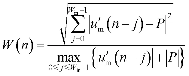
其中
式中,in為最小二乘法所使用的采樣數(shù)據(jù)窗;為當(dāng)前最新采樣點(diǎn)。
距離保護(hù)動(dòng)作判據(jù)為
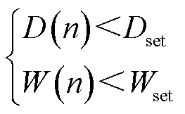
式中,()為當(dāng)前采樣點(diǎn)對(duì)應(yīng)的故障位置結(jié)果;set為保護(hù)范圍整定值;()為采樣點(diǎn)對(duì)應(yīng)的模型誤差;set為模型誤差限值,本文中取0.25。當(dāng)故障位置計(jì)算結(jié)果小于定值,且模型誤差小于限值,距離保護(hù)動(dòng)作。
2 仿真驗(yàn)證
2.1 仿真模型和參數(shù)
利用PSCAD軟件建立了220kV輸電線路模型,如圖5所示,圖中()和()分別為保護(hù)安裝處電壓和電流,MN為線路長度,如未特殊說明,MN=100km。保護(hù)安裝于M側(cè),電流采用羅氏線圈測(cè)量。
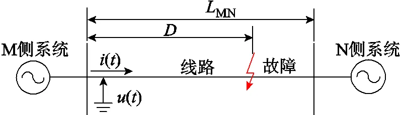
圖5 220kV輸電線路系統(tǒng)模型
輸電線路參數(shù)為:1=0.037 219Ω/km,1= 0.303 986Ω/km,1=0.012 120μF/km,0=0.315 511Ω/km,0=1.081 049Ω/km,0=0.007 758μF/km。
M側(cè)系統(tǒng)采用大、小兩種方式,大方式下參數(shù)為:M1max=10Ω∠86°,M0max=10Ω∠83°;小方式下參數(shù)為:M1min=20Ω∠86°,M0min=20Ω∠83°。N側(cè)系統(tǒng)參數(shù)為:N1=10Ω∠76°,N0=10Ω∠73°。
采用某公司生產(chǎn)的羅氏線圈實(shí)際參數(shù),圖3中線圈內(nèi)阻s=288Ω,電感=58.5mH,負(fù)載電阻a=32kΩ,互感系數(shù)=10.26μH,雜散電容0=30nF。
算法采樣率設(shè)置為4kHz,圖1和圖2中,保護(hù)裝置中數(shù)字低通濾波器為
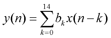
式中,濾波器系數(shù)0~14分別為0.010 500, 0.021 526,0.038 863, 0.059 973, 0.082 118, 0.101 736, 0.115 268, 0.120 103, 0.115 268, 0.101 736, 0.082 118, 0.059 973, 0.038 863, 0.021 526, 0.010 500。
2.2 性能驗(yàn)證
從故障5ms后開始計(jì)算故障點(diǎn)位置,隨采樣點(diǎn)向后移動(dòng)計(jì)算數(shù)據(jù)窗,每個(gè)采樣點(diǎn)計(jì)算一次故障點(diǎn)位置和模型誤差。模擬在距保護(hù)安裝處0.8倍線路全長處發(fā)生不同故障電壓合閘角下的單相接地和相間短路故障,新方法故障位置計(jì)算結(jié)果如圖6所示,模型誤差計(jì)算結(jié)果如圖7所示。
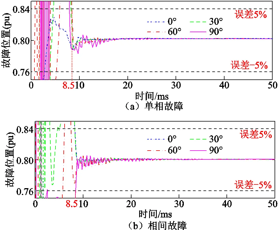
圖6 故障位置計(jì)算結(jié)果
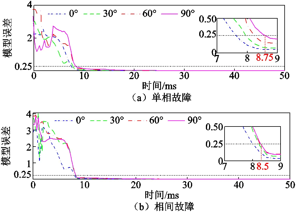
圖7 模型誤差計(jì)算結(jié)果
圖6中橫軸為時(shí)間,以故障發(fā)生時(shí)刻為零時(shí)刻,縱軸為故障位置計(jì)算結(jié)果,數(shù)值為以線路全長為基準(zhǔn)的標(biāo)幺值。圖7中縱軸為模型誤差計(jì)算結(jié)果。仿真結(jié)果表明,在不同故障電壓合閘角下發(fā)生故障時(shí),新方法計(jì)算誤差穩(wěn)定在5%以內(nèi),且模型誤差小于0.25所需的時(shí)間不大于8.75ms。
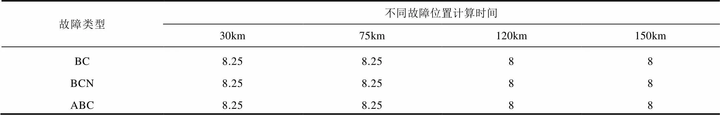
為進(jìn)一步驗(yàn)證本文所提方法的性能,針對(duì)系統(tǒng)大小運(yùn)行方式、不同線路長度、不同故障位置、不同故障類下算法的性能進(jìn)行了仿真,并在100km和150km線路長度下對(duì)新方法的耐受過渡電阻能力進(jìn)行了驗(yàn)證,部分結(jié)果見表1~表4,“NF”表示計(jì)算結(jié)果不在允許誤差范圍以內(nèi)。仿真結(jié)果表明,本文所提方法不受系統(tǒng)運(yùn)行方式、線路長度、故障位置和故障類型的影響,對(duì)于不同類型金屬性故障均可在8.75ms內(nèi)準(zhǔn)確計(jì)算出故障位置,并且具有一定的耐過渡電阻能力。
表1 大方式下100km線路仿真結(jié)果 (單位:ms)
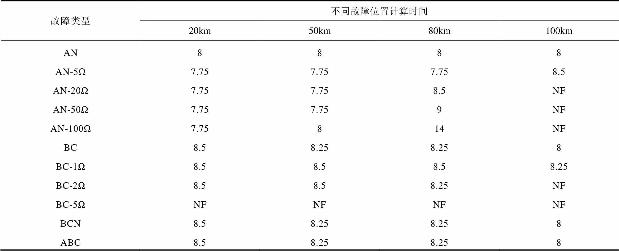
Tab.1 Simulation results for 100km line in the maximum operating mode
表2 小方式下100km線路仿真結(jié)果 (單位:ms)
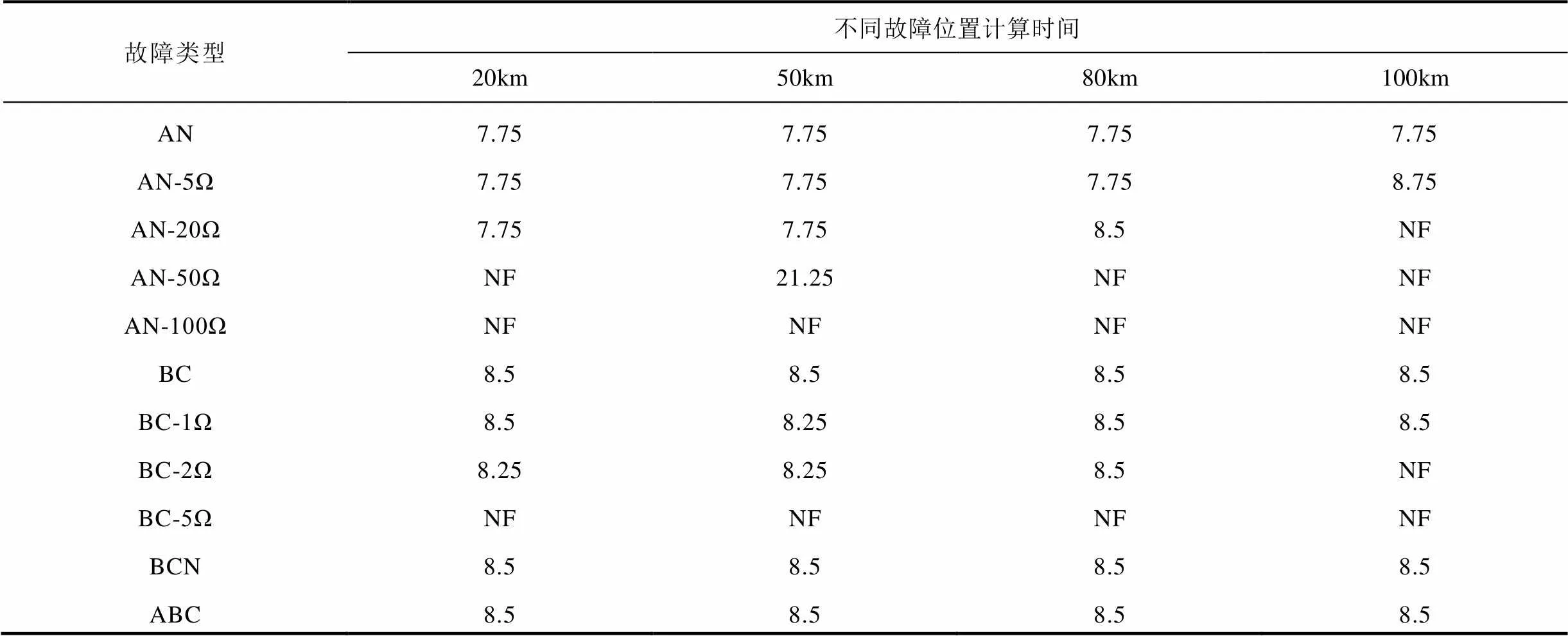
Tab.2 Simulation results for 100km line in the minimum operating mode
表3 大方式下150km線路仿真結(jié)果 (單位:ms)
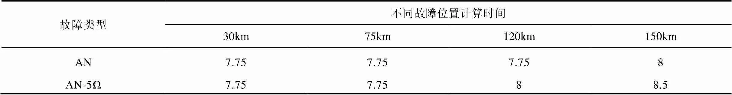
Tab.3 Simulation results for 150km line in the maximum operating mode
(續(xù))
表4 小方式下150km線路仿真結(jié)果 (單位:ms)

Tab.4 Simulation results for 150km line in the minimum operating mode
2.3 不同距離保護(hù)算法性能對(duì)比分析
傳統(tǒng)距離保護(hù)算法的數(shù)據(jù)傳變環(huán)節(jié)如圖1所示。合并單元中數(shù)字積分器的傳遞函數(shù)為
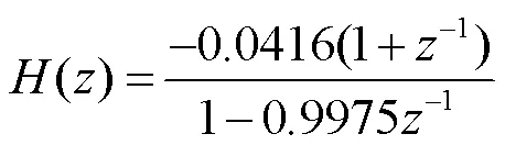
傳統(tǒng)距離保護(hù)算法選取典型的解微分方程算法、全周傅里葉算法、半周差分算法、全周差分算法,其中,解微分方程算法表達(dá)式如式(16)所示,以5ms數(shù)據(jù)窗的數(shù)據(jù)構(gòu)造微分方程組,通過最小二乘法求解。
模擬系統(tǒng)發(fā)生故障工況和系統(tǒng)開關(guān)操作引起的電流數(shù)據(jù)異常工況下各算法的計(jì)算情況,對(duì)本文方法和傳統(tǒng)距離保護(hù)算法性能進(jìn)行比較。
2.3.1 系統(tǒng)故障工況
以圖5所示仿真模型80km處發(fā)生故障為例,對(duì)不同保護(hù)算法的計(jì)算結(jié)果進(jìn)行比較。發(fā)生單相經(jīng)5Ω過渡電阻故障的仿真結(jié)果如圖8所示。
由圖8可知,本文方法的計(jì)算結(jié)果在8ms后計(jì)算誤差始終穩(wěn)定在5%以內(nèi),計(jì)算結(jié)果波動(dòng)范圍小,算法穩(wěn)定性好。解微分方程、全周傅里葉、半周差分和全周差分算法的計(jì)算結(jié)果誤差保持在5%以內(nèi)的時(shí)間分別為30.25ms、29.5ms、15.25ms、31ms,且計(jì)算結(jié)果仍有較大波動(dòng)。
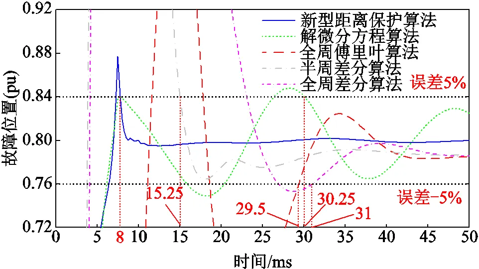
圖8 不同距離保護(hù)算法故障位置計(jì)算結(jié)果
2.3.2 電流數(shù)據(jù)異常工況
模擬電流出現(xiàn)文獻(xiàn)[16]所述的異常情況,對(duì)新方法和傳統(tǒng)距離保護(hù)算法的動(dòng)作行為進(jìn)行對(duì)比。
通過在圖1和圖2所示的數(shù)據(jù)傳變環(huán)節(jié)中羅氏線圈的輸出中疊加采樣異常信號(hào),模擬系統(tǒng)操作開關(guān)時(shí)出現(xiàn)采樣異常信號(hào)情況。電流疊加采樣異常信號(hào)后,合并單元輸出信號(hào)如圖9所示,圖中以采樣異常信號(hào)注入的起始時(shí)刻作為0時(shí)刻。
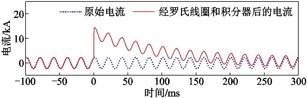
圖9 疊加異常信號(hào)前電流與疊加后積分器輸出電流
由圖9可知,在羅氏線圈的輸出中有采樣異常信號(hào)后,經(jīng)積分器輸出的信號(hào)中附加了衰減直流分量。本文方法的故障位置及模型誤差計(jì)算結(jié)果分別如圖10a和圖10b所示,圖中虛線為距離保護(hù)整定范圍(80km)。由圖10可知,在采樣異常導(dǎo)致故障

圖10 等傳變距離保護(hù)算法故障計(jì)算結(jié)果
位置計(jì)算結(jié)果滿足動(dòng)作條件時(shí),模型誤差不滿足動(dòng)作條件,因此采用本文方法不會(huì)出現(xiàn)誤動(dòng)作。
傳統(tǒng)距離保護(hù)算法的計(jì)算結(jié)果如圖11所示,圖11a、圖11b、圖11c分別為解微分方程算法、全周傅氏、半周差分的計(jì)算結(jié)果,這些算法的計(jì)算結(jié)果在采樣異常時(shí)會(huì)出現(xiàn)較長時(shí)間滿足動(dòng)作條件的情況。圖11d為全周差分算法的計(jì)算結(jié)果,在計(jì)算數(shù)據(jù)滿窗后不會(huì)誤動(dòng)作,但全周差分算法受采樣異常信號(hào)影響的時(shí)間比新方法相對(duì)更長。
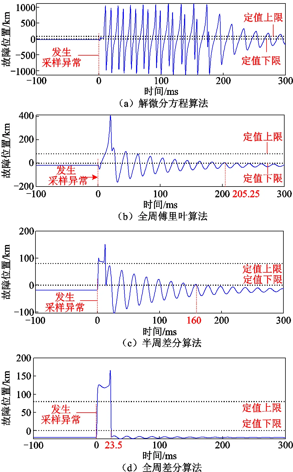
圖11 傳統(tǒng)距離保護(hù)故障位置計(jì)算結(jié)果
仿真測(cè)試結(jié)果表明,在系統(tǒng)發(fā)生故障時(shí),本文方法相對(duì)于傳統(tǒng)保護(hù)算法響應(yīng)速度更快、計(jì)算結(jié)果穩(wěn)定性更好,受采樣異常影響較小。
3 試驗(yàn)驗(yàn)證
為了驗(yàn)證本文提出的方法在實(shí)際保護(hù)裝置中的性能,采用羅氏線圈和繼電保護(hù)裝置搭建如圖12所示的測(cè)試環(huán)境。采用PSCAD仿真軟件建立圖5所示的仿真模型,對(duì)不同故障情況進(jìn)行仿真,生成故障電壓和電流數(shù)據(jù)。采用測(cè)試儀對(duì)故障數(shù)據(jù)進(jìn)行回放,電流量通過羅氏線圈傳變后輸入保護(hù)裝置。線路保護(hù)裝置的采樣頻率為4kHz。
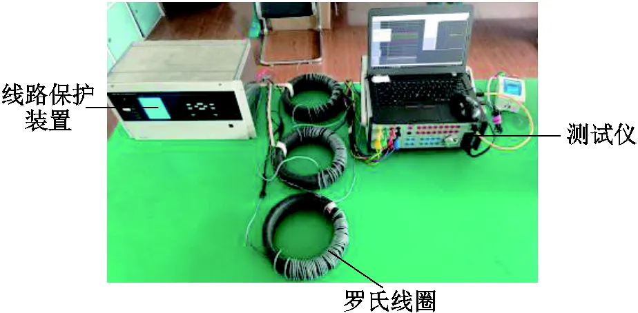
圖12 等傳變距離保護(hù)試驗(yàn)環(huán)境
距離保護(hù)安裝處80km發(fā)生故障時(shí)本方法的計(jì)算結(jié)果如圖13所示。單相故障和相間故障的情況下新方法的計(jì)算誤差穩(wěn)定在5%以內(nèi)的時(shí)間分別為6.5ms和9.5ms。
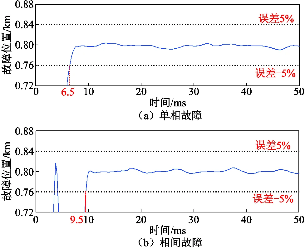
圖13 試驗(yàn)結(jié)果
進(jìn)一步對(duì)線路不同位置發(fā)生不同類型故障的情況進(jìn)行試驗(yàn),部分試驗(yàn)結(jié)果見表5。試驗(yàn)結(jié)果表明,當(dāng)不同位置發(fā)生不同類型故障情況下,本文方法的計(jì)算誤差穩(wěn)定在5%以內(nèi)所需的時(shí)間不超過10ms,與仿真驗(yàn)證結(jié)果一致。
表5 部分試驗(yàn)結(jié)果
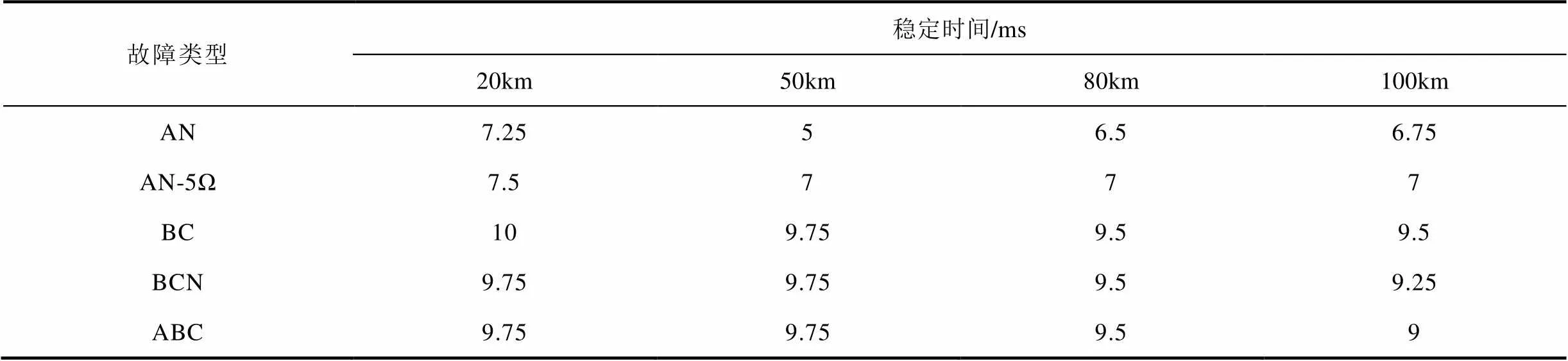
Tab.5 Partial test results
4 結(jié)論
為減小羅氏線圈電流互感器暫態(tài)傳變誤差對(duì)保護(hù)的影響,本文提出了一種等傳變距離保護(hù)方法,并得出以下結(jié)論:
1)根據(jù)輸電線路等傳變理論,電流采用羅氏線圈輸出的微分信號(hào),電壓采用經(jīng)過與羅氏線圈具有相同傳變環(huán)節(jié)的虛擬羅氏線圈后的信號(hào),兩者之間的關(guān)系仍然滿足輸電線路分布參數(shù)模型。
2)本文方法中電流直接采用羅氏線圈輸出的微分信號(hào),消除了傳統(tǒng)羅氏線圈電流互感器的積分環(huán)節(jié)對(duì)繼電保護(hù)的不利影響。
3)各種PSCAD仿真和試驗(yàn)結(jié)果表明,本文方法不受系統(tǒng)運(yùn)行方式、長度線路、故障位置和故障類型的影響,在故障發(fā)生后,計(jì)算誤差穩(wěn)定在5%以內(nèi)所需時(shí)間不大于10ms,且受采樣異常信號(hào)影響較小,性能優(yōu)于現(xiàn)有的距離保護(hù)方法。
[1] 鄧豐, 梅龍軍, 唐欣, 等. 基于時(shí)頻域行波全景波形的配電網(wǎng)故障選線方法[J]. 電工技術(shù)學(xué)報(bào), 2021, 36(13): 2861-2870. Deng Feng, Mei Longjun, Tang Xin, et al. Faulty line selection method of distribution network based on time-frequency traveling wave panoramic waveform[J]. Transactions of China Electrotechnical Society, 2021, 36(13): 2861-2870.
[2] 趙小軍, 王瑞, 杜振斌, 等. 交直流混合激勵(lì)下取向硅鋼片磁滯及損耗特性模擬方法[J]. 電工技術(shù)學(xué)報(bào), 2021, 36(13): 2791-2800. Zhao Xiaojun, Wang Rui, Du Zhenbin, et al. Hysteretic and loss modeling of grain oriented silicon steel lamination under AC-DC hybrid magnetiza-tion[J]. Transactions of China Electrotechnical Society, 2021, 36(13): 2791-2800.
[3] 楊鳴, 熊釗, 司馬文霞, 等. 電磁式電壓互感器“低頻過電壓激勵(lì)-響應(yīng)”逆問題求解[J]. 電工技術(shù)學(xué)報(bào), 2021, 36(17): 3605-3613. Yang Ming, Xiong Zhao, Sima Wenxia, et al. Solution of the inverse problem of “l(fā)ow-frequency overvoltage excitation to response” for electromagnetic potential transformers[J]. Transactions of China Electrotechnical Society, 2021, 36(17): 3605-3613.
[4] 趙志剛, 徐曼, 胡鑫劍. 基于改進(jìn)損耗分離模型的鐵磁材料損耗特性研究[J]. 電工技術(shù)學(xué)報(bào), 2021, 36(13): 2782-2790. Zhao Zhigang, Xu Man, Hu Xinjian. Research on magnetic losses characteristics of ferromagnetic materials based on improvement loss separation model[J]. Transactions of China Electrotechnical Society, 2021, 36(13): 2782-2790.
[5] 鄧成林, 蔡新景, 付丁丁. 電流互感器鐵心剩磁影響因素仿真分析[J]. 電氣技術(shù), 2021, 22(9): 22-26. Deng Chenglin, Cai Xinjing, Fu Dingding. Simulation analysis of factors affecting remanence of current transformer core[J]. Electrical Engineering, 2021, 22(9): 22-26.
[6] 劉毅, 趙勇, 任益佳, 等. 水中大電流脈沖放電電弧通道發(fā)展過程分析[J]. 電工技術(shù)學(xué)報(bào), 2021, 36(16): 3525-3534. Liu Yi, Zhao Yong, Ren Yijia, et al. Analysis on the development process of arc channel for underwater high current pulsed discharge[J]. Transactions of China Electrotechnical Society, 2021, 36(16): 3525-3534.
[7] 朱夢(mèng)夢(mèng), 束洪春, 何兆磊, 等. 接地極直流電流互感器寬頻特性現(xiàn)場(chǎng)試驗(yàn)與分析[J]. 電力系統(tǒng)自動(dòng)化, 2022, 46(6): 166-172. Zhu Mengmeng, Shu Hongchun, He Zhaolei, et al. Field test and analysis of broadband characteristics of DC current transformer on earth electrode[J]. Automation of Electric Power Systems, 2022, 46(6): 166-172.
[8] 廖文彪, 周澤昕, 詹榮榮, 等. 多類型電流互感器混聯(lián)運(yùn)行動(dòng)模測(cè)試平臺(tái)建設(shè)及對(duì)差動(dòng)保護(hù)的影響[J]. 電力系統(tǒng)保護(hù)與控制, 2017, 45(22): 83-89. Liao Wenbiao, Zhou Zexin, Zhan Rongrong, et al. Construction of the dynamic model test platform for hybrid operation of multi type current transformer and its influence on differential protection[J]. Power System Protection and Control, 2017, 45(22): 83-89.
[9] 李振華, 沈聚慧, 李振興, 等. 隔離開關(guān)電弧模型及對(duì)Rowgowski線圈電流互感器的傳導(dǎo)干擾研究[J]. 電力系統(tǒng)保護(hù)與控制, 2020, 48(16): 131-139. Li Zhenhua, Shen Juhui, Li Zhenxing, et al. Research on an arc model of a disconnector for conduction interference of a Rogowski coil electronic transformer[J]. Power System Protection and Control, 2020, 48(16): 131-139.
[10] Li Jue, Liu Hao, Martin K E, et al. Electronic transformer performance evaluation and its impact on PMU[J]. IET Generation, Transmission & Distribution, 2019, 13(23): 5396-5403.
[11] Wang Dong, Gao Houlei, Zou Guibin, et al. Ultra-high-speed travelling wave directional protection based on electronic transformers[J]. IET Generation, Transmission & Distribution, 2017, 11(8): 2065-2074.
[12] Ghanbari T, Samet H, Jarrahi M A, et al. Implementation of Rogowski coil based differential protection on electric arc furnace transformers of mobarakeh steel company: design step[C]//2018 IEEE International Conference on Environment and Electrical Engineering and 2018 IEEE Industrial and Commercial Power Systems Europe, Palermo, 2018: 1-5.
[13] 王宇, 孟令雯, 湯漢松, 等. ECT采集單元積分回路的暫態(tài)特性改進(jìn)及其檢測(cè)系統(tǒng)研發(fā)[J]. 電力系統(tǒng)保護(hù)與控制, 2021, 49(10): 98-104. Wang Yu, Meng Lingwen, Tang Hansong, et al. Improvement of transient characteristics and development of a testing system of an integration circuit in ECT acquisition unit[J]. Power System Protection and Control, 2021, 49(10): 98-104.
[14] 戴魏, 鄭玉平, 白亮亮, 等. 保護(hù)用電流互感器傳變特性分析[J]. 電力系統(tǒng)保護(hù)與控制, 2017, 45(19): 46-54. Dai Wei, Zheng Yuping, Bai Liangliang, et al. Analysis of protective current transformer transient response[J]. Power System Protection and Control, 2017, 45(19): 46-54.
[15] Habrych M, Wisniewski G, Miedziński B, et al. HDI PCB Rogowski coils for automated electrical power system applications[J]. IEEE Transactions on Power Delivery, 2018, 33(4): 1536-1544.
[16] 白世軍, 郭樂, 曾林翠, 等. 變壓器空載合閘對(duì)隔離斷路器電子式CT干擾分析及防護(hù)[J]. 高壓電器, 2018, 54(8): 81-90, 97. Bai Shijun, Guo Le, Zeng Lincui, et al. Interference analysis and protection of electronic current transformer in DCB during no-load closing of transformer[J]. High Voltage Apparatus, 2018, 54(8): 81-90, 97.
[17] Jing Shi, Huang Qi, Tang Fan, et al. Study on additional dynamic component of electronic current transducer based on Rogowski coil and its test approach[J]. IEEE Transactions on Industry Applications, 2020, 56(2): 1258-1265.
[18] 朱夢(mèng)夢(mèng), 羅強(qiáng), 曹敏, 等. 電子式電流互感器傳變特性測(cè)試與分析[J]. 電力系統(tǒng)自動(dòng)化, 2018, 42(24): 143-149. Zhu Mengmeng, Luo Qiang, Cao Min, et al. Test and analysis of transfer characteristics of electronic current transformer[J]. Automation of Electric Power Systems, 2018, 42(24): 143-149.
[19] Pang Fubin, Liu Yu, Ji Jianfei, et al. Transforming characteristics of the Rogowski coil current transformer with a digital integrator for high-frequency signals[J]. The Journal of Engineering, 2019, 2019(16): 3337-3340.
[20] 宋濤. Rogowski線圈電流互感器中的高精度數(shù)字積分器技術(shù)研究[J]. 高電壓技術(shù), 2015, 41(1): 237-244. Song Tao. Technical research of accurate digital integrators for Rogowski coil current transformer[J]. High Voltage Engineering, 2015, 41(1): 237-244.
[21] Jiang Xianguo, Li Zhongqing, Wang Xingguo, et al. Identification methods of SV distortion of smart substation relay protection[C]//2014 International Conference on Power System Technology, Chengdu, 2014: 1963-1968.
[22] 李仲青, 周澤昕, 黃毅, 等. 數(shù)字化變電站繼電保護(hù)適應(yīng)性研究[J]. 電網(wǎng)技術(shù), 2011, 35(5): 210-215. Li Zhongqing, Zhou Zexin, Huang Yi, et al. Research on applicability of relay protection in digital substations[J]. Power System Technology, 2011, 35(5): 210-215.
[23] 文明浩. 基于虛擬電容式電壓互感器的能量平衡保護(hù)[J]. 中國電機(jī)工程學(xué)報(bào), 2007, 27(24): 11-16. Wen Minghao. A new protection scheme based on energy balance with virtual CVT[J]. Proceedings of the CSEE, 2007, 27(24): 11-16.
[24] 文明浩, 陳德樹, 尹項(xiàng)根, 等. 遠(yuǎn)距離輸電線路等傳變瞬時(shí)值差動(dòng)保護(hù)[J]. 中國電機(jī)工程學(xué)報(bào), 2007, 27(28): 59-65. Wen Minghao, Chen Deshu, Yin Xianggen, et al. Long transmission line current differential protection by using instantaneous value after equal transfer processes[J]. Proceedings of the CSEE, 2007, 27(28): 59-65.
[25] 陳玉, 文明浩, 王禎, 等. 基于低頻電氣量的超高壓交流線路出口故障快速保護(hù)[J]. 電工技術(shù)學(xué)報(bào), 2020, 35(11): 2415-2426. Chen Yu, Wen Minghao, Wang Zhen, et al. A high speed protection scheme for outgoing line fault of HVAC transmission lines based on low frequency components[J]. Transactions of China Electrotechnical Society, 2020, 35(11): 2415-2426.
[26] 文明浩, 陳德樹, 尹項(xiàng)根. 超高壓線路等傳變快速距離保護(hù)[J]. 中國電機(jī)工程學(xué)報(bào), 2012, 32(4): 145-150, 6. Wen Minghao, Chen Deshu, Yin Xianggen. Fast distance protection of EHV transmission lines based on equal transfer processes[J]. Proceedings of the CSEE, 2012, 32(4): 145-150, 6.
Distance Relay Based on Rogowski Coil Current Transformer by Using Instantaneous Value after Equal Transfer Processes
Li Baowei1,2Shi Xin2Wang Zhiwei2Wen Minghao1Zhang Xu2
(1. State Key Laboratory of Advanced Electromagnetic Engineering and Technology Huazhong University of Science and Technology Wuhan 430074 China 2. XJ Electric Co. Ltd Xuchang 461000 China)
Since the output voltage of the coil is proportional to the rate of change of the primary current, it is required to be integrated to recover the measured current, which is usually realized by electronic integrator circuits. High-frequency transient signals tend to be generated during power system operation or short-circuit faults. After being processed by the integrator, the output signal of electronic transformer may be seriously distorted, resulting in mal-operation of the relay. Many researchers have proposed a variety of detection methods for abnormal output of the Rogowski coil, but the impact of additional components caused by integrators on protection cannot be avoided. An improved method of line relay directly using the differential output of Rogowski coil is put forward. Besides, a distance relay based on Rogowski coil current transformer by using instantaneous value after equal transfer processes is proposed. In the novel scheme, the current differential signal output by Rogowski coil is directly used to eliminate the influence of transient transmission error introduced by integrator.
Firstly, according to the equal transfer process of transmission lines(ETPTL) theory, the virtual Rogowski coil digital transmission link is constructed to process the voltage signal with the same transmission characteristics as the Rogowski coil digital transmission link, so that the voltage and current signals used for distance protection pass through the same transmission link. Secondly, the R-L equations are solved by least square method to calculate the fault location, so as to improve the stability of the calculation results. Thirdly, the voltage at the fault point is reconstructed and passed through the digital transmission link of virtual Rogowski coil to make it have the same transient transmission process as the voltage at the protection installation, so as to reduce the initial calculation error of fault and accelerate the convergence of fault calculation to stability. Finally, a method of model error discrimination is proposed. According to the R-L model, the voltage of the protection installation can be calculated from the calculation results of the fault location. It is compared with the actual voltage at the protection installation site to verify the calculation results of fault location, so as to prevent the distance protection from misoperation under working conditions such as abnormal data interference.
Simulation results demonstrate that the performance of the proposed distance relay method is not affected by the system operation mode, line length, fault location and fault type. In the case of metal fault, it can accurately calculate the fault location within 8.75 ms, and has a certain ability to withstand transition resistance. Compared with the traditional algorithm, the new algorithm has faster calculation speed, smaller fluctuation range and better stability under fault conditions and it is less affected by abnormal current signal transfer. To verify the performance of the improved distance relay algorithm proposed in this paper in practical applications, an actual Rogowski coil and relay device are used to build a test environment to test different fault conditions. The experiment results show that when different faults occur at different points, the time required for the measurement error of the improved distance relay to stabilize within 5% does not exceed 10ms, which is consistent with the simulation test results.
The study comes to the following conclusions: (1) According to the ETPTL theory, the current signal directly adopts the differential output of Rogowski coil, the voltage signal adopts the output of a virtual Rogowski coil with the same transfer features, so the relationship between them still satisfy the distributed parameter model of the original transmission line. (2) The current signal of the improved distance relay is directly from the Rogowski coil transducer without the integrator. It can radically eliminate the impacts of the Rogowski coil transducer integrator on the relay. (3) Various PSCAD simulation and experiment results show that it takes no more than 10ms for the measurement error of the improved distance relay to be stabilized within 5%, which is signed prior to the present method. The novel proposal immunes to system operation mode and can be applied to different length lines.
Rogowski coil, integrator, distance relay, virtual type of Rogowski coil, equal transfer process
國家自然科學(xué)基金項(xiàng)目(51877090)和國家電網(wǎng)有限公司總部科技項(xiàng)目(4000-202222070A-1-1-ZN)資助。
2021-10-20
2022-04-13
10.19595/j.cnki.1000-6753.tces.211661
TM773
李寶偉 男,1984年生,博士研究生,高級(jí)工程師,研究方向?yàn)殡娏ο到y(tǒng)保護(hù)與控制。E-mail:xjtc_libaowei@126.com(通信作者)
石 欣 女,1983年生,碩士,高級(jí)工程師,研究方向?yàn)殡娏ο到y(tǒng)建模仿真。E-mail:xjtc_shixin@126.com
(編輯 赫蕾)
猜你喜歡
汽車維修與保養(yǎng)(2019年7期)2020-01-06 03:30:42
兒童故事畫報(bào)(2019年5期)2019-05-26 14:26:14
汽車維護(hù)與修理(2016年10期)2016-07-10 08:17:41
Coco薇(2016年2期)2016-03-22 02:42:52
Coco薇(2015年1期)2015-08-13 02:47:34
小雪花·成長指南(2015年7期)2015-08-11 15:03:12
小雪花·成長指南(2015年4期)2015-05-19 14:47:56
汽車維修與保養(yǎng)(2015年12期)2015-04-18 07:51:49
汽車維修與保養(yǎng)(2015年6期)2015-04-17 03:31:50
汽車維修與保養(yǎng)(2015年2期)2015-04-17 01:30:34