氮摻雜碳納米管包覆Fe0.64Ni0.36@Fe3NiN 核殼結構用于高穩定鋅-空氣電池
2024-07-04 00:00:00蒲晨鄧代潔李赫楠徐麗
物理化學學報 2024年2期

摘要:可逆鋅-空氣電池因其高功率密度和環境友好性而得到了廣泛研究。然而,氧還原反應(ORR)和氧析出反應(OER)的緩慢動力學限制了其實際應用。迄今為止,二氧化銥和二氧化釕被認為是氧還原反應的最佳電催化劑,同時鉑碳被認為是最有效的氧還原反應的電催化劑。然而,由于Pt、Ir和Ru的天然豐度低、成本高的原因,它們在ZABs中的實際應用嚴格受限。因此,探索低成本和高性能的雙功能催化劑對促進可充電鋅-空氣電池的發展至關重要。具有高導電性、低氧還原反應能壘的過渡金屬合金可作為有潛力的氧還原電催化劑。然而,為提高過渡金屬合金催化劑的雙功能催化活性,可構筑過渡金屬合金@過渡金屬氮化物的核殼結構。在此,我們設計了一種氮摻雜碳納米管包覆Fe0.64Ni0.36@Fe3NiN核殼結構(Fe0.64Ni0.36@Fe3NiN/NCNT)的雙功能電催化劑,其具有高效的雙功能催化活性。核殼結構可以為ORR/OER產生更多的活性點。Fe0.64Ni0.36核具有高導電性,有助于電荷轉移。Fe3NiN殼有助于提升催化劑的OER性能。氮摻雜碳納米管不僅能夠有效增強傳質效應和內部電荷傳遞,還可以提升其電化學活性表面積。此外,具有高抗腐蝕性能的Fe3NiN外殼可以有效地保護Fe0.64Ni0.36內核,從而提高了電化學過程中催化劑的穩定性。氮摻雜碳納米管對Fe0.64Ni0.36@Fe3NiN核殼結構也具有一定的保護作用,因此Fe0.64Ni0.36@Fe3NiN/NCNT表現出優異的穩定性。Fe0.64Ni0.36@Fe3NiN/NCNT催化劑表現出優異的雙功能氧電催化性能,ORR的半波電位為0.88 V,在10 mA·cm?2時的OER過電位為380 mV,以及高電化學穩定性(8 h后電流密度剩余92.8%)。此外,與基于Pt/C + IrO2 (155 mW·cm?2)和Fe0.64Ni0.36/NCNT (89 mW·cm?2)的鋅-空氣電池相比,基于Fe0.64Ni0.36@Fe3NiN/NCNT的鋅-空氣電池展現出更高的功率密度(214 mW·cm?2),提供781mAh·g?1的高容量,并展現出了超長的循環穩定性(循環壽命超過1100 h)。我們相信這項工作將對于新型催化劑設計有所啟發,從而實現高度穩定和高效的鋅-空氣電池。
關鍵詞:雙功能電催化劑;Fe3NiN;核殼結構;鋅-空氣電池;長循環壽命
中圖分類號:O646
Abstract: Rechargeable zinc-air batteries (ZABs) havebeen extensively investigated owing to their high powerdensity and environmental friendliness. However, the slowkinetics of the oxygen reduction reaction (ORR) and oxygenevolution reaction (OER) processes limit their practicalapplication. Currently, IrO2 and RuO2 are considered theoptimal OER electrocatalysts, and Pt/C is the most effectiveORR electrocatalyst. However, the practical application of Pt,Ir, and Ru in ZABs is severely limited owing to their low naturalabundance and high cost. Therefore, the fabrication ofinexpensive and high-performance bifunctional catalysts is essential for the development of rechargeable ZABs. Transitionmetalalloys have a high electrical conductivity and low energy barrier for the reaction of oxygen, and thus they areconsidered promising ORR electrocatalysts. Transition-metal nitride-transition-metal alloy core-shell nanostructures canbe fabricated to improve the bifunctional electrocatalytic activity. In this study, a bifunctional electrocatalyst withFe0.64Ni0.36@Fe3NiN core-shell structures encapsulated in N-doped carbon nanotubes (Fe0.64Ni0.36@Fe3NiN/NCNT) wasdesigned for highly efficient rechargeable ZABs. Fe0.64Ni0.36@Fe3NiN/NCNT was synthesized by pyrolyzing the nickel-ironlayereddouble hydroxide (NiFe-LDH) precursor, followed by ammonia etching of the Fe0.64Ni0.36 alloy. The core-shellstructure produced more ORR/OER active sites. The Fe0.64Ni0.36 core exhibited high electrical conductivity, which facilitatescharge transfer. The Fe3NiN shell enhanced the OER performance and improved the bifunctional performance. Moreover,the NCNT structures not only efficiently enhanced the mass transfer efficiency and intrinsic electrical conductivity, but alsoprovided a large electrochemical active surface area. The high anticorrosion property of the Fe3NiN shell effectivelyprotected the Fe0.64Ni0.36 core, which consequently enhanced electrocatalyst stability during the electrochemical processes.The protective carbon layer and the superior chemical stability of the Fe3NiN shell resulted in the ultrahigh stability ofFe0.64Ni0.36@Fe3NiN/NCNT. The catalyst exhibited an excellent bifunctional oxygen electrocatalytic performance, with ahalf-wave potential of 0.88 V for the ORR and low OER overpotential of 380 mV at 10 mA·cm?2. Moreover, the catalystexhibited electrochemical stability (92.8% current retention after 8 h). In addition, the Fe0.64Ni0.36@Fe3NiN/NCNT-basedZAB exhibited a higher peak power density (214 mW?cm?2) than the ZABs based on Pt/C+IrO2 (155 mW?cm?2) andFe0.64Ni0.36/NCNT (89 mW?cm?2). Moreover, the Fe0.64Ni0.36@Fe3NiN/NCNT-based ZAB delivered a high capacity of 781mAh?g?1, while the ZABs based on Fe0.64Ni0.36/NCNT and Pt/C+IrO2 reached capacities of 688 and 739 mAh?g?1,respectively. Furthermore, the Fe0.64Ni0.36@Fe3NiN/NCNT-based ZAB exhibited ultralong cycling stability (cycle life gt; 1100h), which exceeded those of Pt/C (50 h) and Fe0.64Ni0.36/NCNT (450 h). We propose that this study will facilitate the designof novel catalysts for highly stable and efficient ZABs.
Key Words: Bifunctional electrocatalyst; Fe3NiN; Core-shell structure; Zinc-air battery; Ultra-long cycle stability
1 Introduction
Among the many renewable energy conversion devices, zincairbatteries (ZABs) have attracted abundant attention in bothacademic and industrial communities due to their environmentalfriendliness, high stability and high theoretical energy density(1086 Wh·kg?1) 1,2. However, the practical efficiency of theZABs is inevitably affected by the slow kinetics of oxygenreduction reaction (ORR) and oxygen evolution reaction(OER) 3–6. Currently, Ru/Ir-based OER electrocatalysts and PtbasedORR electrocatalysts with a high price and scarcity arelimited in large-scale commercialization 7–10. Therefore, thedeveloping of high-efficiency, cost-effective, and stablebifunctional oxygen electrocatalysts are highly essential.
Currently, transition-metal-based electrocatalysts (metalalloy, metal oxides, carbides, hydroxides, phosphides, sulfidesand nitrides) are gravitating more focus on their abundance andpotential catalytic performance 11–14. Among these materials,transition metal alloys not only possess high electricalconductivity but can lower the oxygen reaction energy barrier byinducing internal electron redistribution 15–17. Therefore, transitionmetal alloys are considered promising electrocatalysts 18,19. Thedissolution of transition metal alloys in alkaline remains asubstantial issue. And, the most effective and cost-effective strategy to prevent this corrosion during the oxygen reaction isthe introduction of carbon substrates which can encapsulate thealloy nanoparticles 20. Moreover, the introduction of carbonsubstrates can conspicuously avoid aggregation, broadening thesurface area and fully exposing the active sites 15–19.Nevertheless, transition metal alloys exhibit limited bifunctionalactivity 21–23. The improvement strategies of bifunctional activityneed to be explored urgently. Nowadays, transition metalnitrides are gravitating more focus for their unique electronicstructure, superior chemical stability and excellent mechanicalrobustness. The M― N bonding of transition metal nitridesinduces the expansion of the parent lattice and shrinkage of themetal d-band, leading to a similar electronic structure of preciousmetals at the Fermi level and fundamentally changing theactivity of the catalytic site 14,24,25. Moreover, transition metalnitrides have abundant valence states and provide a largeflexibility for the regulation of the electronic structure. Withgreat flexibility for modulation, transition metal nitrides can beendowed with promising bifunctional electrocatalyticactivities 14,26. Therefore, through constructing the transitionmetal nitrides-transition metal alloys core@shell nanostructure,the bifunctional electrocatalytic activity can be effectivelyimproved.
Herein, the Fe0.64Ni0.36@Fe3NiN core@shell nanostructureencapsulated in N-doped carbon nanotubes(Fe0.64Ni0.36@Fe3NiN/NCNT) was successfully synthesized bysurface ammonia etching of the nickel-iron alloys (Fig. 1a). TheFe0.64Ni0.36 alloy can enhance the conductivity of Fe3NiN. TheFe3NiN shell can enhance the performance of OER and improvethe dual-function performance. Meanwhile, the dense Fe3NiNshell with high thermal stability and corrosion resistance caneffectively protect the Fe0.64Ni0.36 core, which promotesremarkable activity and stability in ORR and OER processes.Notably, the Fe0.64Ni0.36@Fe3NiN/NCNT exhibited a high halfwavepotential (E1/2) of 0.88 V for ORR and a low overpotential(380 mV) for OER. Moreover, the Fe0.64Ni0.36 alloy stronglyinduces the construction of N-doped carbon nanotube (NCNT)which can not only provide a large electrochemical activesurface area (ECSA) but protect the Fe0.64Ni0.36@Fe3NiNcore@shell nanostructure from harsh electrochemicalcorrosion 27,28. Thus, the current density ofFe0.64Ni0.36@Fe3NiN/NCNT remains at 92.8% after 8 h ofelectrochemical measurements. Moreover, the assembledZABs with Fe0.64Ni0.36@Fe3NiN/NCNT exhibit a highefficiency with an ultra-long cycle life of 1100 h.
2 Experimental and computational section
2.1 Chemicals
Ferric(III) nitrate nonahydrate (Fe(NO3)3·9H2O, 99%),nickel(II) nitrate hexahydrate (Ni(NO3)2·6H2O, 99%), urea(CO(NH2)2, 99%), sulfuric acid (H2SO4, 98.3%) and ethanol(C2H5OH, 99.7%) were obtained from Sino Pharm ChemicalReagent Co., Ltd. (Shanghai, China). Commercial Pt/C (20 wt%)and IrO2 (99.9%) were procured from Alfa Aesar Chemicals Co.Ltd. (Shanghai, China). Nafion (5 wt%) was purchased fromSigma-Aldrich Chemie Gmbh (Shanghai, China). Grapheneoxide (GO) was purchased from Nanjing XFNANO MaterialsTech Co., Ltd. (Nanjing, China).
2.2 Synthesis of Fe0.64Ni0.36/NCNT
Firstly, melamine, melic acid and urea were mixed and ballmilled (molar ratio = 1 : 1 : 3), and then underwent a thermaltreatment at 550 °C for 4 h with a heating rate of 2 °C·min?1under a nitrogen atmosphere to synthesize g-C3N4 29. Followinga typical procedure, 0.200 g of g-C3N4, 0.231 g ofFe(NO3)3·9H2O, 0.0665 g of Ni(NO3)2·6H2O, 0.360 g of urea,and 0.0150 g of GO were dissolved in 40 mL deionized water.The solution was sonicated for 30 min. Next, the final mixturewas transferred to a Teflon-lined steel autoclave and heated at120 °C for 18 h in an oven. The sediment was collected bycentrifugation and washed three times with deionized water andethanol, then centrifuged and dried overnight in a vacuum ovenat 60 °C. After grinding the dried solid, the sample was heatedat 850 °C for 1 h with a heating rate of 5 °C·min?1 under an argonatmosphere. After cooling to room temperature, the calcinedblack sample was removed from the tube and then dispersed in an H2SO4 solution (0.5 mol·L?1) for 12 h. The abovementionedsample was washed in deionized water until neutral and thendried at 60 °C. The Fe0.64Ni0.36 alloys/nitrogen-doped carbonnanotube (Fe0.64Ni0.36/NCNT) was formed.
2.3 Synthesis of Fe0.64Ni0.36@Fe3NiN/NCNT
The Fe0.64Ni0.36@Fe3NiN/NCNT catalyst was obtained bysurface ammonia etching of Fe0.64Ni0.36/NCNT. TheFe0.64Ni0.36/NCNT was nitrided in a mixture of ammonia andargon atmosphere at 800 °C for 2 h in a tube furnace with aheating rate of 5 °C·min?1. The resulting catalysts were denotedas Fe0.64Ni0.36@Fe3NiN/NCNT.
2.4 Synthesis of Fe2N/NC, NG and NCNT
The synthesis of Fe2N/NC and NG is similar to the abovementionedone for the Fe0.64Ni0.36/NCNT. The starting solutionswere replaced by 0.200 g of g-C3N4, 0.242 g of Fe(NO3)3·9H2O,0.360 g of urea, and 0.0150 g of GO for synthesizing Fe2N/NC.The starting solutions were replaced by 0.200 g of g-C3N4, 0.360g of urea, and 0.0150 g of GO for synthesizing NG. Meanwhile,the acid cleaning step was abandoned during the synthesis. TheCNT and g-C3N4 were placed in a tubular furnace, heated to850 °C for 1 h to produce the NCNT catalyst.
3 Results and discussion
The formation process of the Fe0.64Ni0.36@Fe3NiNencapsulated in N-doped carbon nanotubes is illustrated in Fig.1a. In brief, a combination of hydrothermal method, alloyingprocedure and ammonia treatment was adopted to form the finalcatalyst. Above all, the nickel-iron layered double hydroxideprecursor was prepared by a facile hydrothermal reaction. Afterthe pyrolysis process at 850 °C, the formed alloy can directlycatalyze carbon sources into highly interconnected NCNTs (Fig.S1a, Supporting Information). It is worth mentioning that theNCNTs with supplementary active sites can not only providehigh dispersibility but promote electron transfer 30,31. In the finalstep of catalyst preparation, Fe0.64Ni0.36@Fe3NiN/NCNT wasprepared by ammonia treatment of the Fe0.64Ni0.36/NCNT.
The scanning electron microscopy (SEM) image reveals thespecific network structure composed of 1D carbon nanotubes(Fig. 1b), which can enhance mass-transport efficiency 32. Thetransmission electron microscopy (TEM) image ofFe0.64Ni0.36@Fe3NiN/NCNT displays that the nanoparticles witha diameter of about 20–50 nm are embedded in the tip of NCNTs(Fig. 1c). The specific carbon nanotube structure cannot befound in the SEM of NG and Fe2N/NC (Fig. S1b,c), which provethat Fe0.64Ni0.36 can catalyze the conversion of carbon source intoNCNT at a high temperature. Moreover, the high-resolutionTEM (HRTEM) verifies the Fe0.64Ni0.36@Fe3NiN core-shellstructure. The lattice fringe of 0.219, 0.218, and 0.220 nm relatesto the (111) facet of Fe3NiN as the shell part after the ammoniaetching of Fe0.64Ni0.36 alloy surfaces (Fig. 1d). The lattice fringeof the core part is 0.208 and 0.205 nm corresponding (111)planes of Fe0.64Ni0.36 alloy. And the lattice fringe of 0.34 nmcorresponds to the (003) lattice plane of graphite-3R (Fig. 1d) 33.Through pyrolyzing the NiFe LDH precursor and then ammoniaetching the Fe0.64Ni0.36 alloy, Fe3NiN nitride was successfullyformed on the surface of the Fe0.64Ni0.36 alloy. Similarly, Wanget al. produced nitrides on the TiNbZrTa/CrFeCoNi alloysurface by magnetron sputtering 34. Liu et al. reported a 3Delectrode configuration composed of metallic NiConitrides/NiCo2O4/GF as a pH-universal bifunctionalelectrocatalyst by being heated at 400 °C in an NH3 atmospherefor 2 h 35. Besides, Kuttiyiel et al. synthesized iridium-nickelnitride shell on the IrNi cores and then evaluated their activity inthe hydrogen evolution reaction through ammonia etching in510 °C 36. Besides, the particle of Fe0.64Ni0.36@Fe3NiN is tightlywrapped in a layer of NCNT with a thickness of about 3.3 nm.Fig. S2 exhibits the Raman spectra of theFe0.64Ni0.36@Fe3NiN/NCNT, Fe0.64Ni0.36/NCNT and NG. Theintensity ratios of the ID/IG peaks were calculated to be 1.08(Fe0.64Ni0.36@Fe3NiN/NCNT), 0.98 (Fe0.64Ni0.36/NCNT) and0.92 (NG). It demonstrates that the Fe0.64Ni0.36@Fe3NiN/NCNThas more defects than Fe0.64Ni0.36/NCNT and NG 37,38. The energydispersive spectroscopy (EDS) of Fe0.64Ni0.36@Fe3NiN/NCNTimplies that the N, Ni, and Fe elements are evenly distributedover the particle (Fig. 1e).
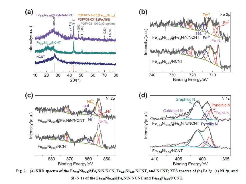
After annealing the Fe0.64Ni0.36/NCNT precursor for 1 h, Xraydiffraction (XRD) pattern of the as-obtainedFe0.64Ni0.36@Fe3NiN/NCNT can be indexed to the cubic Fe3NiNphase (PDF#09-0318) (Fig. 2a) and Fe0.64Ni0.36 (PDF#47-1405) 39,40. The 2θ values of 41.186°, 48.103° and 70.176°correspond to the (111), (200) and (220) crystal facets,respectively. Additionally, two peaks for (200) and (220) latticeplanes slightly shift to lower diffraction angles (Fig. S3) due tocrystal defects or distortion resulting from the core-shellstructures, which finally brings extra active sites for oxygenreaction 41,42. The peak located at 26.6° can be indexed to the(003) lattice plane of the rhombohedral graphite structure(PDF#26-1079) 43, consistent with TEM results. The X-rayphotoelectron spectroscopy (XPS) was carried out to furtherconfirm the chemical composition and valence states of theFe0.64Ni0.36@Fe3NiN/NCNT catalyst. The survey spectrum ofFe0.64Ni0.36@Fe3NiN/NCNT exhibits the presence of typicalpeaks of C 1s, O 1s, N 1s, Fe 2p and Ni 2p (Fig. S4). The peaksof the Fe 2p spectrum at 707.06 and 708.38 eV correspond to Fe0species and Fe―Nx (Fig. 2b). The peak at 711.20 and 713.72 eVis corresponding to Fe2+ and Fe3+, respectively. In addition, thepeaks at 715.22 eV can be assigned to the satellite peaks 16,42.The Ni 2p spectrum of Fe0.64Ni0.36@Fe3NiN/NCNT shows theappearance of Ni0, Ni―Nx, Ni2+, Ni3+, and the satellite peaks at853.24, 853.92, 855.08, 857.46 and 861.24 eV (Fig. 2c),respectively. The appearance of Fe―Nx and Ni―Nx is inaccordance with the Fe3NiN phase shown in the XRD pattern.After the ammonia treatment, the contents of metal-nitrogenspecies significantly increase (Table S1 and S2, SupportingInformation). The N 1s spectrum (Fig. 2d) ofFe0.64Ni0.36@Fe3NiN/NCNT can be divided into five characteristic peaks of pyridinic N (398.42 eV), Fe/Ni―Nx(399.04 eV), pyrrolic N (399.41 eV), graphitic N (401.08 eV)and oxidized N (404.14 eV), further certifying the existence ofmetal nitrides 16,17. The nitrogen species are mainly graphitic Nand pyridinic N (Table S3). The pyridinic N is the active site ofthe oxygen reduction reaction. The graphitic N can enhance theconductivity to improve the current density 46,47. Compared tothe N 1s spectra from the Fe0.64Ni0.36/NCNT, theFe0.64Ni0.36@Fe3NiN/NCNT has significantly less pyrrolic Nand more Fe/Ni―Nx species (Table S3), which is consistent withthe findings from the spectra of Fe 2p and Ni 2p.
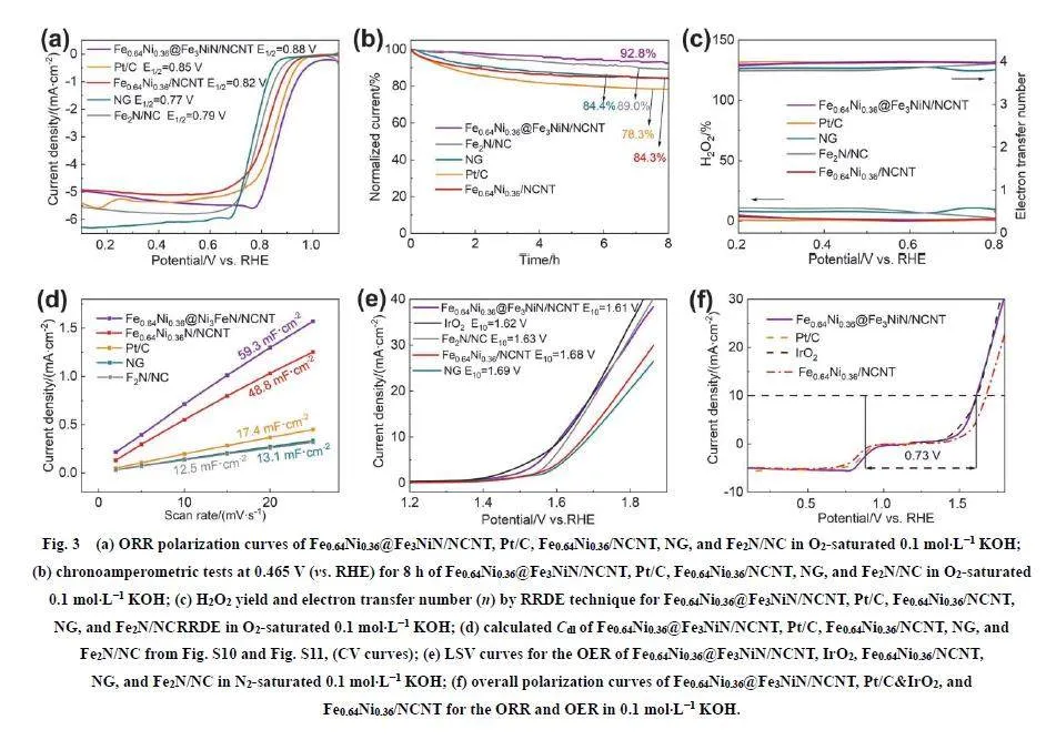
To measure the electrocatalytic performance ofFe0.64Ni0.36@Fe3NiN/NCNT, a three-electrode system has beenconstructed in 0.1 mol·L?1 KOH electrolyte with saturated O2 orN2. Cyclic voltammetry (CV) curves are shown in Fig. S5 andFig. S6 to evaluate the ORR activity of the electrocatalysts. Thecharacteristic oxygen reduction peaks appear in all samples(Fe0.64Ni0.36@Fe3NiN/NCNT, Fe0.64Ni0.36/NCNT, Fe2N/NC, NGand Pt/C). The CV curves of Fe0.64Ni0.36@Fe3NiN/NCNTexhibit an oxygen reduction peak at 0.77 V, which is larger thanthat of Fe0.64Ni0.36/NCNT (0.69 V). This result indicates that theFe0.64Ni0.36@Fe3NiN/NCNT exhibits excellent ORR performance.The catalytic performances of Fe0.64Ni0.36@Fe3NiN/NCNT,Fe0.64Ni0.36/NCNT, Fe2N/NC, NG and noble-metal catalysts(Pt/C for ORR, IrO2 for OER) were estimated through linearsweep voltammetry (LSV) measurements in 1.0 mol·L?1 KOHelectrolyte with saturated O2 (Fig. 3a,e). The LSV curves exhibitthe ORR performance with an onset and half-wave potential(E1/2) of 1.02 and 0.88 V for Fe0.64Ni0.36@Fe3NiN/NCNT.Compared with the Fe0.64Ni0.36@Fe3NiN/NCNT, thecommercial Pt/C (0.95 and 0.85 V), Fe0.64Ni0.36/NCNT (0.93 and0.82 V), Fe2N/NC (0.90 and 0.79 V) and NG (0.87 and 0.77 V)show low onset and half-wave potential. While the NCNTexhibits a lower onset potential (0.80 V) and half-wave potential(0.68 V) (Fig. S7). Chronoamperometry tests were performed toconfirm the ORR stability. After 8 h, the current density ofFe0.64Ni0.36@Fe3NiN/NCNT remains 92.8%, which is better thanthat of Fe0.64Ni0.36/NCNT (84.3%), Fe2N/NC (89.0%), NG(84.4%) and Pt/C (78.3%) (Fig. 3b). This remarkable stability ofFe0.64Ni0.36@Fe3NiN/NCNT can be attributed to the metalnitride layer and carbon substrate with high crystallinity, whichcan protect nanoparticles from corrosion during the harshelectrochemical process 13. Besides, the rotating ring diskelectrode (RRDE) test shows that the H2O2 yield ofFe0.64Ni0.36@Fe3NiN/NCNT is below 5% in the potentialranging of 0.2–0.8 V, which is close to that of Pt/C andFe0.64Ni0.36/NCNT. The electron-transfer number is 3.82–3.97,reconfirming a four-electron transfer pathway (Fig. 3c). Thecorresponding LSV curves of RRDE tests are exhibited in Fig.S8. The electron transfer properties were evaluated throughelectrochemical impedance spectra (EIS).Fe0.64Ni0.36@Fe3NiN/NCNT possesses the smallest radius circle(Fig. S9), suggesting a higher charge-transfer efficiency owingto the specific structure. The electrochemical active surface area(ECSA) was evaluated based on the proportional relationshipbetween ECSA and electrochemical double-layer capacitance(Cdl), which was obtained by measuring the non-Faradaic current(Fig. S10 and Fig. S11). The Cdl of Fe0.64Ni0.36@Fe3NiN/NCNTcatalyst is 59.3 mF·cm?2 which is larger than those of 48.8mF·cm?2 for Fe0.64Ni0.36/NCNT catalyst, 17.4 mF·cm?2 for Pt/C,12.5 mF·cm?2 for Fe2N/NC catalyst and 13.1 mF·cm?2 for NG(Fig. 3d). It indicates that more active sites are activated whenFe0.64Ni0.36 and Fe3NiN are coupled together with a core-shellstructure. The larger ECSA is due to the lower charge-transferresistance and the structure of carbon nanotube 13. The OERperformances of the catalysts were evaluated in 0.1 mol·L?1KOH electrolyte with saturated N2. TheFe0.64Ni0.36@Fe3NiN/NCNT shows an overpotential of 380 mVat a current density of 10 mA·cm?2 (Fig. 3e), which is lower thanthat of the commercial IrO2 (390 mV), Fe2N/NC (400 mV),Fe0.64Ni0.36/NCNT (450 mV) and NG (460 mV). The surface ofFe3NiN can reconstruct into an amorphous FeNi-containingoxyhydroxide shell which serves as the real active species duringthe OER process 11,48. Thus, the Fe3NiN shell in the surface ofthe Fe0.64Ni0.36 core contributes to enhancing the performance ofOER. Measuring the potential gap ΔE (= Ej=10 ? E1/2) betweenthe half-wave potential (E1/2) of ORR and potential of OER(Ej=10) at a current density of 10 mA·cm?2 is calculated toevaluate bifunctional oxygen reaction activity. TheFe0.64Ni0.36@Fe3NiN/NCNT has shown an excellent ΔE of 0.73 V,which is superior to the Pt/C for ORR and IrO2 for OER (ΔE =0.77 V) and the Fe0.64Ni0.36/NCNT (ΔE = 0.85 V) (Fig. 3f),surpassing many works reported previously (Table S4).Additionally, by comparing to the performance of somepreviously reported outstanding bifunctional catalysts, theFe0.64Ni0.36@Fe3NiN/NCNT indeed exhibits a better bifunctionalperformance (ΔE = 0.73 V, Table S4). In summary, the reasonsfor the enhanced electrocatalytic performance can be attributedto the following factors: 1) Fe0.64Ni0.36 core possesses highelectrical conductivity which contributes to the charge transfer.The Fe3NiN shell with superior chemical stability can serve as aprotection layer to enhance the stability of theFe0.64Ni0.36@Fe3NiN/NCNT. 2) The nitride@alloy core-shellstructure can produce more active sites for ORR/OER. TheFe3NiN shell can enhance the performance of OER, whicheventually lead to improving the dual-function performance. 3)The NCNT catalyzed by Fe0.64Ni0.36 possesses a high degree ofgraphitization and a high level of graphitic-N active sites, whichcan efficiently enhance the mass transfer efficiency and intrinsicelectrical conductivity. And, the carbon layer can furthersignificantly protect the internal particle during theelectrochemical test, resulting in ultra-high cyclic stability.
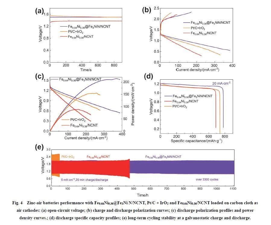
The excellent bifunctional performance of the core-shellstructure ensures that the Fe0.64Ni0.36@Fe3NiN/NCNT can be anideal catalyst for the real application of rechargeable zinc-airbatteries. To demonstrate that, a classical rechargeable zinc-airbattery was assembled by applying the Fe0.64Ni0.36@Fe3NiN/NCNTas the cathode. For comparison, two batteries loading the Pt/C +IrO2 and Fe0.64Ni0.36/NCNT catalysts respectively were alsoestimated under the same test condition. TheFe0.64Ni0.36@Fe3NiN/NCNT-based ZABs display an opencircuitvoltage as large as 1.51 V (Fig. 4a), which is close to thatof Pt/C + IrO2-based ZABs (1.51 V) and Fe0.64Ni0.36/NCNTbasedZABs (1.38 V). The charge and discharge polarizationcurves have been recorded at current density varying from 0 to400 mA·cm?2 in Fig. 4b. The Fe0.64Ni0.36@Fe3NiN/NCNT-basedZABs present a low charge-discharge voltage gap compared withthe Pt/C + IrO2-based ZABs. The Fe0.64Ni0.36@Fe3NiN/NCNTbasedZABs deliver a maximum power density of 214 mW·cm?2at 364 mA·cm?2 (Fig. 4c), which is higher than that of Pt/C +IrO2 (155 mW·cm?2) and Fe0.64Ni0.36/NCNT (89 mW·cm?2),outperforming many reported ZABs in the recent works (TableS5). Besides, the Fe0.64Ni0.36@Fe3NiN/NCNT-based ZABs candeliver a high capacity of 781 mAh·g?1 at a current density of 20mA·cm?2, while the Fe0.64Ni0.36/NCNT and Pt/C + IrO2 reach at688 and 739 mAh·g?1 (Fig. 4d). During the discharge operation,no conspicuous voltage drop was observed. To verify the highstability of this specific structure in the real application, thecharge-discharge cycle curve (20 min for each charge anddischarge) was tested on the constant current density (5 mA·cm?2).As shown in Fig. 4e, the Fe0.64Ni0.36@Fe3NiN/NCNT-basedZABs display remarkable long-term durability over 3300 cyclesin 1100 h. The Fe0.64Ni0.36@Fe3NiN/NCNT-based ZABsdelivered a smaller voltage gap (1.04 V), indicating bettercharge-discharge performance. And the steady energy efficiencyis about 52.3%. However, a gradual increase in the voltage gapcan be observed in the Fe0.64Ni0.36/NCNT-based ZABs aftertesting about 450 h. It proves that the Fe3NiN shell inFe0.64Ni0.36@Fe3NiN/NCNT can enhance the stability ofFe0.64Ni0.36@Fe3NiN/NCNT-based ZABs.
4 Conclusions
In summary, the Fe0.64Ni0.36@Fe3NiN core@shellnanostructure encapsulated in N-doped carbon nanotubes wassuccessfully prepared via a facile strategy of pyrolyzing the NiFeLDH precursor and ammonia etching the Fe0.64Ni0.36 alloy. TheFe3NiN can be formed by ammonia etching the Fe0.64Ni0.36 alloyto obtain core@shell nanostructure which can provide morecatalytic active sites. The Fe3NiN contributes to enhancing theperformance of OER and leads to improving the dual-functionperformance. The Fe0.64Ni0.36@Fe3NiN/NCNT can significantlyobtain the outstanding oxygen reaction performance (ΔE = 0.73 V)with high ORR (E1/2 = 0.88 V) and OER (Ej=10 = 1.61 V)activities. Besides, the nitride layer with high crystallinity couldalso protect the Fe0.64Ni0.36@Fe3NiN from being directlyexposed to an electrochemical environment. Consequently,when Fe0.64Ni0.36@Fe3NiN/NCNT was applied as the cathode inZABs, it exhibits a high peak power density (214 mW·cm?2) anda prominent long-term durability (1100 h) in practicalapplications. The ultra-high cycling stability benefits from theprotection of the carbon layer in NCNT and the superiorchemical stability of Fe3NiN. This work provides a reasonablestrategy to design and synthesize core-shell electrocatalysts withhigh performance for zinc-air batteries.
Author Contributions: Methodology, Validation,Investigation, Data Curation, Writing-Original DraftPreparation, Chen Pu; Investigation, Data Curation, Writing-Original Draft Preparation, Daijie Deng; Conceptualization,Supervision, Writing-Review amp; Editing, Resources, ProjectAdministration, Henan Li and Li Xu.
Supporting Information: available free of charge via the Internet at http://www.whxb.pku.edu.cn.
References
(1) Kundu, A.; Mallick, S.; Ghora, S.; Raj, C. R. ACS Appl. Mater.Interfaces 2021, 13, 40172. doi: 10.1021/acsami.1c08462
(2) Wu, M.; Zhang, G.; Wu, M.; Prakash, J.; Sun, S. Energy StorageMater. 2019, 21, 253. doi: 10.1016/j.ensm.2019.05.018
(3) Tian, H.; Song, A. L.; Zhang, P.; Sun, K. A.; Wang, J.; Sun, B.; Fan,Q. H.; Shao, G. J.; Chen, C.; Liu, H.; et al. Adv. Mater. 2023, 35,2210714. doi: 10.1002/adma.202210714
(4) Anand, P.; Wong, M. S.; Fu, Y. P. Energy Storage Mater. 2023, 58,362. doi: 10.1016/j.ensm.2023.03.033
(5) Deng, D. J.; Ma, H. X.; Wu, S. Q.; Wang, H.; Qian, J. C.; Wu, J. C.;Li, H. M.; Yan, C.; Li, H. N.; Xu, L. Renewables 2023, Accepted.doi: 10.31635/renewables.023.202200020
(6) Wu, S. Q.; Deng, D. J.; Zhang, E. J.; Li, H. N.; Xu, L. Carbon 2022,196, 347. doi: 10.1016/j.carbon.2022.04.043
(7) Lee, C.; Shin, K.; Park, Y.; Yun, Y. H.; Doo, G.; Jung, G. H.; Kim,M.; Cho, W.; Kim, C.; Lee, H. M.; et al. Adv. Funct. Mater. 2023, 32,2301557. doi: 10.1002/adfm.202301557
(8) Hong, S.; Ham, K.; Hwang, J.; Kang, S.; Seo, M. H.; Choi, Y.; Han,B.; Lee, J.; Cho, K. Adv. Funct. Mater. 2023, 33, 2209543.doi: 10.1002/adfm.202209543
(9) Zhao, S. Y.; Liu, T.; Dai, Y. W.; Wang, J.; Wang, Y.; Guo, Z. J.; Yu,J.; Bello, I. T.; Ni, M. Appl. Catal. B 2023, 320, 121992.doi: 10.1016/j.apcatb.2022.121992
(10) Liu, M. L.; Zhao, Z. P.; Duan, X. F.; Huang, Y. Adv. Mater. 2019, 31,1802234. doi: 10.1002/adma.201802234
(11) Lai, C.; Gong, M.; Zhou, Y.; Fang, J.; Huang, L.; Deng, Z.; Liu, X.;Zhao, T.; Lin, R.; Wang, K.; et al. Appl. Catal. B 2020, 274, 119086.doi: 10.1016/j.apcatb.2020.119086
(12) Liu, W.; Zhang, J.; Bai, Z.; Jiang, G.; Li, M.; Feng, K.; Yang, L.;Ding, Y.; Yu, T.; Chen, Z.; et al. Adv. Funct. Mater. 2018, 28,1706675. doi: 10.1002/adfm.201706675
(13) Wu, M.; Zhang, G.; Chen, N.; Hu, Y.; Regier, T.; Rawach, D.; Sun, S.ACS Energy Lett. 2021, 6, 1153. doi: 10.1021/acsenergylett.1c00037
(14) Wang, H.; Li, J.; Li, K.; Lin, Y.; Chen, J.; Gao, L.; Nicolosi, V.;Xiao, X.; Lee, J. M. Chem. Soc. Rev. 2021, 50, 1354.doi: 10.1039/D0CS00415D
(15) Xiong, Q.; Zheng, J.; Liu, B.; Liu, Y.; Li, H.; Yang, M. Appl. Catal. B2023, 321, 122067. doi: 10.1016/j.apcatb.2022.122067
(16) Ma, Y.; Chen, W.; Jiang, Z.; Tian, X.; Wang, X.; Chen, G.; Jiang, Z.-J.J. Mater. Chem. A 2022, 10, 12616. doi: 10.1039/D2TA03110H
(17) Kim, K.; Min, K.; Go, Y.; Lee, Y.; Shim, S. E.; Lim, D.; Baeck, S. H.Appl. Catal. B 2022, 315, 121501. doi: 10.1016/j.apcatb.2022.121501
(18) Wu, Z.; Lu, X. F.; Zang, S.; Lou, X. W. Adv. Funct. Mater. 2020, 30,1910274. doi: 10.1002/adfm.201910274
(19) Huang, Z. F.; Wang, J.; Peng, Y.; Jung, C. Y.; Fisher, A.; Wang, X.Adv. Energy Mater. 2017, 7, 1700544. doi: 10.1002/aenm.201700544
(20) Li, G.; Tang, Y.; Fu, T.; Xiang, Y.; Xiong, Z.; Si, Y.; Guo, C.; Jiang,Z. S. Chem. Eng. J. 2022, 429, 132174. doi: 10.1016/j.cej.2021.132174
(21) Chen, K.; Kim, S.; Rajendiran, R.; Prabakar, K.; Li, G.; Shi, Z.;Jeong, C.; Kang, J.; Li, O. L. J. Colloid Interface Sci 2021, 582, 977.doi: 10.1016/j.jcis.2020.08.101
(22) Sheng, K.; Yi, Q.; Chen, A. L.; Wang, Y.; Yan, Y.; Nie, H.; Zhou, X.ACS Appl. Mater. Interfaces 2021, 13, 45394.doi: 10.1021/acsami.1c10671
(23) Xu, X.; Xie, J.; Liu, B.; Wang, R.; Liu, M.; Zhang, J.; Liu, J.; Cai, Z.;Zou, J. Appl. Catal. B 2022, 316, 121687.doi: 10.1016/j.apcatb.2022.121687
(24) He, X.; Tian, Y.; Huang, Z.; Xu, L.; Wu, J.; Qian, J.; Zhang, J.; Li, H.J. Mater. Chem. A 2021, 9, 2301. doi: 10.1039/D0TA10370E
(25) Liu, Z.; Liu, D.; Zhao, L.; Tian, J.; Yang, J.; Feng, L. J. Mater. Chem.A 2021, 9, 7750. doi: 10.1039/D1TA01014J
(26) Ban, J.; Xu, H.; Cao, G.; Fan, Y.; Pang, W. K.; Shao, G.; Hu, J. Adv.Funct. Mater. 2023, 33, 2300623. doi: 10.1002/adfm.202300623
(27) Jiang, R.; Tung, S. O.; Tang, Z.; Li, L.; Ding, L.; Xi, X.; Liu, Y.;Zhang, L.; Zhang, J. Energy Storage Mater. 2018, 12, 260.doi: 10.1016/j.ensm.2017.11.005
(28) Guo, Y.; Yuan, P.; Zhang, J.; Xia, H.; Cheng, F.; Zhou, M.; Li, J.;Qiao, Y.; Mu, S.; Xu, Q. Adv. Funct. Mater. 2018, 28, 1805641.doi: 10.1002/adfm.201805641
(29) Ong, W. J.; Tan, L. L.; Ng, Y. H.; Yong, S. T.; Chai, S. P. Chem. Rev.2016, 116, 7159. doi: 10.1021/acs.chemrev.6b00075
(30) Kang, J.; Zhang, H. Y.; Duan, X. G.; Sun, H. Q.; Tan, X. Y.; Liu, S.M.; Wang, S.B. Chem. Eng. J. 2019, 362, 251.doi: 10.1016/j.cej.2019.01.035.
(31) Yang, L.; Zhang, X.; Yu, L.; Hou, J.; Zhou, Z.; Lv, R. Adv. Mater.2022, 34, 2105410. doi: 10.1002/adma.202105410
(32) Zhao, B.; Wu, Y.; Han, L.; Xia, Z.; Wang, Q.; Chang, S.; Liu, B.;Wang, G.; Shang, Y.; Cao, A. Energy Storage Mater. 2022, 50, 344.doi: 10.1016/j.ensm.2022.05.029
(33) Chen, Z.; Qin, Y.; Ren, Y.; Lu, W.; Orendorff, C.; Roth, E. P.; Amine,K. Energy Environ. Sci. 2011, 4, 4023. doi: 10.1039/c1ee01786a
(34) Wang, J.; Shu, R.; Chai, J.; Rao, S. G.; Le Febvrier, A.; Wu, H.; Zhu,Y.; Yao, C.; Luo, L.; Li, W.; et al. Mater. Des. 2022, 219, 110749.doi: 10.1016/j.matdes.2022.110749
(35) Liu, Z.; Tan, H.; Liu, D.; Liu, X.; Xin, J.; Xie, J.; Zhao, M.; Song, L.;Dai, L.; Liu, H. Adv. Sci 2019, 6, 1801829.doi: 10.1002/advs.201801829
(36) Kuttiyiel, K. A.; Sasaki, K.; Chen, W. F.; Su, D.; Adzic, R. R.J. Mater. Chem. A 2014, 2, 591. doi: 10.1039/C3TA14301E
(37) Deng, D.; Qian, J.; Liu, X.; Li, H.; Su, D.; Li, H.; Li, H.; Xu, L. Adv.Funct. Materials 2022, 32, 2203471. doi: 10.1002/adfm.202203471
(38) Deng, D.; Wu, S.; Li, H.; Li, H.; Xu, L. Small 2023, 19, 2205469.doi: 10.1002/smll.202205469
(39) López-Callejas, R.; Valencia-Alvarado, R.; Mu?oz-Castro, A. E.;Godoy-Cabrera, O. G.; Barocio, S. R.; Chávez-Alarcón, E. Vacuum2004, 76, 287. doi: 10.1016/j.vacuum.2004.07.060
(40) Zhang, C.; Li, J.; Shi, C.; He, C.; Liu, E.; Zhao, N. J. Energy Chem.2014, 23, 324. doi: 10.1016/S2095-4956(14)60154-6
(41) Chen, M.; Lu, S.; Fu, X.; Luo, J. Adv. Sci. 2020, 7, 1903777.doi: 10.1002/advs.201903777
(42) Wu, M.; Zhang, G.; Qiao, J.; Chen, N.; Chen, W.; Sun, S. NanoEnergy 2019, 61, 86. doi: 10.1016/j.nanoen.2019.04.031
(43) Park, J.; Yoon, K. Y.; Kwak, M. J.; Lee, J. E.; Kang, J.; Jang, J. H.ACS Appl. Mater. Interfaces 2021, 13, 54906.doi: 10.1021/acsami.1c13872
(44) Xu, L.; Wu, S.; He, X.; Wang, H.; Deng, D.; Wu, J.; Li, H. Chem.Eng. J. 2022, 437, 135291. doi: 10.1016/j.cej.2022.135291
(45) Lou, Y.; Liu, J.; Liu, M.; Wang, F. ACS Catal. 2020, 10, 2443.doi: 10.1021/acscatal.9b03716
(46) Xia, D.; Yang, X.; Xie, L.; Wei, Y.; Jiang, W.; Dou, M.; Li, X.; Li, J.;Gan, L.; Kang, F. Adv. Funct. Mater. 2019, 29, 1970332.doi: 10.1002/adfm.201970332
(47) Zhang, J.; Sun, Y.; Zhu, J.; Kou, Z.; Hu, P.; Liu, L.; Li, S.; Mu, S.;Huang, Y. Nano Energy 2018, 52, 307.doi: 10.1016/j.nanoen.2018.08.003
(48) Tang, H.; Yang, D.; Lu, M.; Kong, S.; Hou, Y.; Liu, D.; Liu, D.; Yan,S.; Chen, Z.; Yu, T.; et al. J. Mater. Chem. A 2021, 9, 25435.doi: 10.1039/D1TA07561F
國家自然科學基金(22178148, 22278193)資助項目