穩定界面助力石墨實現超長儲鉀性能
2024-07-04 00:00:00許濤孫偉孔天賜周杰錢逸泰
物理化學學報 2024年2期
關鍵詞:界面
摘要:石墨作為鋰離子電池的商業陽極材料,由于其高豐度、低成本和低電位的優勢,在K離子電池中也顯示出了的巨大潛力。然而,K離子半徑(0.138 nm)大于Li離子半徑(0.076 nm),會造成的明顯結構損傷導致明顯的容量衰減和不穩定的循環壽命。在這里,我們用簡單有效的微波方法通過石墨烯涂層設計了石墨陽極的穩定界面。微波還原可以在10 s內有效地去除氧化石墨烯的氧基,這一點得到了X射線光電子能譜(XPS)的證實。石墨烯涂層不僅可以緩沖石墨的體積膨脹以抑制結構崩潰,還可以加速電子傳輸以提高倍率性能。石墨烯涂層負極(GCG)在3000次循環后表現出262 mAh·g?1的超級循環穩定性。與石墨相比GCG的倍率性能也更加優異(500 mA·g?1的電流密度下容量為161.2 mAh·g?1)。相反,在相同的電流密度下,石墨的容量在150次循環后衰減到小于150 mAh·g?1。進一步的電化學阻抗(EIS)和恒電流間歇滴定(GITT)測試表明,與石墨相比,GCG表現出更快的電導率和離子擴散。循環后的拉曼光譜、掃描電鏡(SEM)和透射電鏡(TEM)圖像驗證了石墨烯作為緩沖界面有利于電極結構的完整性和固體電解質膜(SEI)的穩定性。這項工作為鉀離子電池的大規模應用提供了新的希望。
關鍵詞:鉀離子電池;負極;石墨烯;微波還原;界面
中圖分類號:O646
Stable Graphite Interface for Potassium Ion Battery Achieving Ultralong Cycling Performance
Abstract: Graphite has been extensively employed ascommercial anode material in Li-ion batteries due to its highabundance, low cost, and negative electrode potential.Furthermore, it has demonstrated significant potential for use in Kionbatteries. However, distinct structural damage caused by thelarger radius of K-ion (0.138 nm) compared to that of Li-ion (0.076nm) leads to obvious capacity decay and unstable cycle life. It iscrucial to improve the cycling stability of graphite in potassium ionbatteries (PIBs). Herein, we design a stable interface of graphiteanode by graphene coating with a simple and efficient microwavemethod. According to X-ray photoelectron spectroscopy (XPS),microwave reduction can effectively remove the oxygen group ofgraphene oxide (GO) within 10 s. The graphene coating can buffer the volume expansion of the graphite to suppressstructural collapse; it can also accelerate electronic transmission to improve rate performance. As a result, the graphenecoatinggraphite anode, named GCG, exhibits super cycling stability with a capacity of 262 mAh·g?1 after 3000 cycles at acurrent density of 0.2 A·g?1, which means it can operate smoothly for one year. In contrast, at the same current density,graphite exhibits capacity fading to less than 150 mAh·g?1 after 150 cycles. Moreover, compared to graphite, GCGdemonstrates better rate performance achieving a capacity of 161.2 mAh·g?1 at 500 mA·g?1. Further electrochemicalimpedance spectroscopy (EIS) and galvanostatic intermittent titration technique (GITT) tests show that GCG exhibits fasterelectrical conductivity and ion diffusion compared to graphite. Raman spectroscopy, scanning electron microscopy (SEM),and transmission electron microscopy (TEM) images after cycling verify that the graphene buffer interface benefits theintegrity of the electrode structure and improves the stability of the solid electrolyte interphase (SEI). Compared to graphite,the GCG anode exhibits better performance, as follows: 1) The graphene coating inhibits exfoliation of graphite duringcycling, solving the problem of graphite anode’ short cycling life, and 2) the graphene protective layer improves the iondiffusion rate, resulting in better rate performance of the GCG. In addition, this approach offers the advantages of simpleoperation and low cost, hopefully enabling large-scale applications of potassium-ion batteries.
Key Words: Potassium ion battery; Anode; Graphene; Microwave reduction; Interface
1 Introduction
Clean and renewable energies play an important role inresolving the environment pollution and reducing the emissionof greenhouse gas. Batteries as an excellent energy storagesystem is vital for the efficient utilization of energy 1. Currently,the cost of commercial lithium-ion batteries (LIB) is gettinghigher and higher because of the gradual depletion of lithiumresource 2–4. Potassium ion batteries (PIBs) are regarded as analternative choice for the sufficient potassium sources 5,6 in theearth and a low standard reduction potential of K/K+ (?2.93 Vvs. SHE (standard hydrogen electrode)), which is closing to theLi/Li+ (?3.04 V vs. SHE). Besides, the K-ion exhibits the smallerStokes’ radius of (0.36 nm) in conventional propylene carbonatesolvent that benefits for the higher ion conductivity anddiffusion. What’s more worth mentioning is that PIBs can alsouse aluminum foil to replace copper foil as the anode currentcollector since the alloying reaction between potassium andaluminum do not occur at a low potential, which will furtherdecrease the cost of batteries. Therefore, exploiting highperformanceelectrode materials of KIBs is an important goal inenergy storage.
To date, various anodes materials had been reported for PIBs,in which carbon-based materials has been regarded as mostsuitable materials 7–10. Graphite, applied in LIBs commercially,also has a great potential for large-scale applications to PIBsbecause of the low cost and the low charge-discharge voltageplateau. More importantly, the K+ ion can insert into graphite(like Li+) and form graphite intercalation compounds (KC8),corresponding to the theoretical capacity of 279 mAh·g?1 11.However, the radium of K-ion (0.138 nm) is larger than that ofLi-ion (0.076 nm) and Na-ion (0.102 nm) 12, leading to the distinct structure damage of anode materials during thepotassiation-depotassiation process, which will trigger theobvious capacity decay and unstable cycle life. What’s more, thelayered structure of graphite is easy to be exfoliated during theintercalation process of potassium ion, which makes it difficultto form a uniform and dense solid electrolyte interphase (SEI)film during the charging and discharging process. So it isimportant to develop efficient method to stable the structure ofgraphite with an ultralong cycling life.
Reduced graphene oxide (rGO) is widely used as theprotective layer for metal-ion batteries, benefiting from the largespecific surface area, superior mechanical elasticity and highelectrical conductivity 13,14. For instance, Hou et al. 15 designeda 3D Nb2C/rGO by using rGO as a porous framework achievinga reversible capacity of 301.7 mAh·g?1 after 500 cycles at 2A·g?1. He at al. 16 also designed an rGO/expend graphite/rGOsandwich that coats EG with reduced graphene oxide to bufferthe volumetric variation of EG to improve the cyclic stability ofthe electrode. However, rGO prepared by the chemical reductionis usually highly defective and rich in residual oxygen groups,which are harmful to SEI stability 17. Conventional thermalreduction often involve the high energy cost and long processperiod. Microwave reduction as the fast and effective methodhave received a lot of attention. Recently, Voiry et al. 18 preparedthe high-quality graphene via microwave reduction of solutionexfoliatedgraphene oxide. Zhao et al. 19 produced the N- and Sdopedgraphene with the superior K-storage capability via themicrowave method.
Herein, we develop the microwave reduction method toprepare the graphene-coating graphite composites (GCG) withhigh efficiency. According to previous reports 18 and our experimental results, the proportion of carbon atoms can beincreased to more than 90% by microwave reduction aftergraphene oxide coated graphite. For the poor microwaveabsorption capacity of GO, we adopt graphite with thedelocalized π electrons to enhance localized heating and reduceGO. The obtained graphene as the stable interface improved thecycling stability and rate performance of graphite. Theaccelerated kinetic process is investigated via electrochemicalimpedance spectroscopy (EIS) and galvanostatic intermittenttitration technique (GITT). Furthermore, the stability of structureof graphite and SEI is also explored via the X-ray photoelectronspectroscopy (XPS), scanning electron microscopy (SEM), andtransmission electron microscopy (TEM).
2 Experimental section
2.1 Material synthesis
The preparation of GO: Weigh 5 g graphite sheet and 3.75 gsodium nitrate into a beaker, 160 mL concentrated sulfuric acidwas added while stirring, stirred for 0.5 h, slowly add 20 gKMnO4, continue stirring for 12 h, and then stand for 24 h,slowly add 500 mL deionized water, and slowly add 30 mLH2O2, centrifugation, washing, dialysis for 6–7 d.
In a typical synthesis of GCG, the commercial graphite wasmixed with graphene oxide with the mass ratio of 4 : 1. After 30min stirring and then freeze-dried to obtain GCG samples. Afterthat, the GCG was microwave reduced in the microwave ovenfor 10 s. The microwave was produced by a domestic microwaveoven (Midea, 700 W). A container which can pumped to vacuumwas used as the reactor.
2.2 Characterization of the samples
The structures of the samples are measured by X-raydiffraction (XRD) on a Philips X’ Pert Super diffractometer withCu Kα (λ = 0.154182 nm), and Raman spectroscopy is performedby a JYLABRAM-HR Confocal Laser Micro-Ramanspectrometer at 532 nm. The morphologies of the samples arecharacterized on scanning electron microscopy (SEM,GeminiSEM 450 Carl Zeiss, Germany), transmission electronmicroscopy (TEM, Hitachi H7650, Japan) and high resolutiontransmission electron microscopy (HRTEM, JEOL-JEM-2100F,Japan). X-ray photoelectron spectrum is collected on anESCALAB 250 X-ray photoelectron spectrometer (Perkin-Elmer ESCALAB 250X, America).
2.3 Electrochemical measurements
The graphite and GCG electrodes were prepared by firstmixing graphite or GCG active materials, Super P conductiveadditives, and a carboxymethyl cellulose (CMC) binder, at amass ratio of 8 : 1 : 1, in deionized water solvent, using ballmilling for 12 h. The obtained slurry was then cast on a Cucurrent collector using a scraper and dried at 80 °C for 10 h.Subsequently, the electrode was cut into disks (diameter, 14 cm)with an active material loading of (≈ 1 mg·cm?2). 2016-typeKIBs were assembled in the glove box with the G or G@C workelectrodes, a K metal disk (diameter, 1.5 cm; Alfa Aesar; 99.9%)as the counter electrode, a glass fiber separator, and 0.8 mol·L?1KPF6 in an EC (ethylene carbonate)-DEC (diethyl carbonate)(1 : 1 by volume) electrolyte (the amount of electrolyte in eachbattery was 100 μL). The cycling and C-rate performances in the0.005–3 V range (vs. K/K+) tested at 25 °C using a CT2001Asystem (Wuhan LAND). The cyclic voltammogram (CV)measurements and electrochemical impedance spectroscopy(EIS) are performed on a CHI 660D ElectrochemicalWorkstation (Shanghai Chenhua Corp).
3 Results and discussion
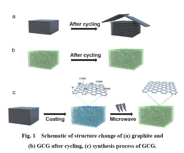
As displayed in Fig. 1a,b, compared with the exfoliated andbroken structure of graphite after cycling, GCG retained theintegrity of the structure, benefiting from the buffer effect ofgraphene in the volume expansion of graphite, which leads to thestable SEI film and cycling performance. Besides, the grapheneaccelerated the electronic and ion transport. The preparationprocedure of the GCG is illustrated in Fig. 1c. Commercialgraphite was first mixed with the GO solution prepared by themodified Hummers method. After freeze-drying, the driedsample was put inside the microwave oven for 10 s. Graphite asa dielectric material has a sp2 bonded carbon network withdelocalized π electrons and exhibits good microwave absorptionproperties. Under the microwave irradiation, temperature ofgraphite rises sharply first and graphite transfer heat to GOinstantaneous. The instantaneous high energy can dissociate thesurface oxidation groups of GO into H2O and CO2. During thisprocess, most of the residual oxygen groups in graphene oxidescan be reduced and the GCG is obtained.
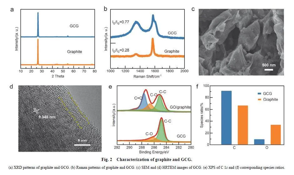
X-ray diffraction (XRD) patterns (Fig. 2a) for graphite andGCG both show a broad peak at 26.5° corresponding to the (002)crystallographic planes of graphite, which indicates that themicrowave irradiation does not destroy the structure of graphite.As shown in Fig. 2b, the graphite represents a strong G peak(at ≈ 1580 cm?1) 20 and a weak D peak (at ≈ 1350 cm?1), with aID/IG intensity ration of about 0.28. However, because of thesurface graphene coating, both the G peak and D peak of GCGare very strong, and the ID/IG value (about 0.77) is also higher than that of graphite, which confirms the noncrystallized coatingsurface.
The morphology and microstructure of GCG and graphite arefurther characterized via scanning electron microscopy (SEM)and transmission electron microscopy (TEM). Graphite shows atypical scaly structure (Fig. S1, Supporting Information). Aftermicrowave irradiation, the graphite is well-coated by grapheneas shown in Fig. 2c. The low-magnification TEM (Fig. S2a,Supporting Information) and high-resolution TEM (HRTEM)(Fig. 2d) images of GCG also suggest that the graphene has agood protection to graphite. The HRTEM image of GCG revealsthat the interlayer spacing is about 0.35 nm, corresponding to the(002) lattice plane of graphite. Furthermore, comparing with thebig volume of graphite, the thickness of graphene layer is about3 nm which will not affect the intercalation of potassium ion.
To further know the property changes before and aftermicrowave irradiation of GCG, the samples were characterizedby surface-sensitive X-ray photoelectron spectroscopy (XPS).As the result shown in Fig. 2e,f, the microwave irradiation canreduce the GO effectively. The GO coating graphite exhibits atypical C=O, C―O and C―C 21,22 species in C 1s spectra (Fig.2e), and C=O and C―O in O 1s spectra (Fig. S3a, SupportingInformation). After microwave irradiation, the GCG exhibits anintense C―C peak and a weak C―O peak (Fig. 2e) indicatingthat after the microwave reduction, the main oxygen groups ofGO had been removed, which is also confirmed by the changeof element ratio of GCG. The ratio of oxygen is reduced to lessthan 10% (Fig. 2f), although the peak of oxygen can still bedetected (Fig. S3b, Supporting Information). Overall,microwave irradiation can reduce graphene with high efficientand form a thick artificial SEI on the surface of graphite.
3.1 Electrochemical performance of the GCG anodes
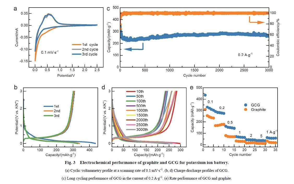
The electrochemical performance of the GCG anodes wasinvestigated in CR2016 type KIBs, which was assembled with0.8 mol·L?1 KPF6 in EC-DEC (1 : 1 by volume) as theelectrolyte. From the cyclic voltammetry curve (CV, Fig. 3a),the obvious reduction peaks at 0.20 and 0.31 V in initial cyclewhich disappear in the following scans, should be attributed tothe decomposition of the electrolyte and the side reaction ofelectrolyte with electrode surface. The peaks at 0.48 and 0.56 Vrespond to the depotassiation process. The reclosing of nextcycles also indicating the surface stability of GCG after the firstcycle.
The charge-discharge curves of GCG shown in Fig. 3b exhibitthat the discharge and charge capacities in the first cycle are435.5 and 309.4 mAh·g?1, respectively, corresponding to theinitial coulombic efficiency of 71.05%. The lower first coulombefficiency than graphite (79.02%, Fig. S4), may attribute to thehigh surface of graphene which will bring more side effects atthe first cycle.
To further explore the effect of the graphene in GCG, thecycling stability is tested at the current density of 0.2 A·g?1. Asshown in Fig. 3c, GCG exhibits superior cycle stability with thereversible capacity of 262 mAh·g?1 after 3000 cycles. However,graphite delivers a rapidly capacity fading at the current densityof 0.2 A·g?1, with the capacity decreasing to less than 150mAh·g?1 after 150 cycles. The improved electrochemicalperformance of GCG is ascribed to the buffer effect of graphenein the volume expansion of graphite. It is worth noting that thecharge-discharge profiles of GCG still overlap well even after3000 cycles (Fig. 3d), which also confirms the better cyclingstability of GCG. Moreover, GCG also exhibits an enhanced rate performance. The reversible capacities of 320.5, 276, 150.1,65.4, 43.2 and 36.1 mAh·g?1 are achieved at 0.1, 0.2, 0.5, 1, 2and 5 A·g?1, respectively. When the current density comes backto 1 A·g?1, the capacity is still 62.1 mAh·g?1 (Fig. 3e). Thesuperior electrochemical performance of GCG than graphiteindicates that the lay of graphene can not only protect graphiteto achieve an ultralong cycle life, but also accelerate ion andelectron transmission to improve the rate performance.
3.2 Potassium storage mechanisms of GCG anode
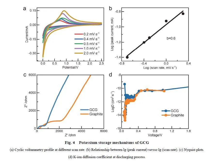
To further study the potassium storage mechanisms of GCGelectrode, CV curves with different scan rates were investigated.Fig. 4a shows five of CV curves at the scan rates of 0.2–2mV?s?1. Kinetic behavior information can be obtained from thefollows 23–25:
I = avb (1)
lgi = blgv + lga (2)
where a and b denote constant, i represents peak current, vdenotes scan rate. And the value of b is determined by the slopeof lgi ? lg (scan rate). When b = 0.5, diffusion dominates thecharging and discharging process. When b = 1, the capacitiveprocess contributes the capacity. As displayed in Fig. 4b, the bvalue was calculated as 0.6 based on the lgi ? lgv curves, whichis large than 0.5 and less than 1, indicating the capacitive-controland diffusion-control co-exist for the K-ion storage 9.
The electrochemical impedance spectroscopy (EIS) andgalvanostatic intermittent titration technique (GITT) test wereconducted 26,27 to further understand the kinetics of K+intercalation/deintercalation in GCG (Fig. 4c,d, Fig. S6–7). Theinterfacial impendance value of GCG and graphite can be judgedfrom Nyquist plots (Fig. 4c). All samples demonstrate anintercept with the x-axis, a semicircle and the line in lowfrequency region, corresponding to the electrolyte (Re), chargetransfer (Rct), and ion diffusion resistance (Zw), respectively 28,29.Especially, the slope of GCG is larger than graphite which meansthat K+ diffusion and charge transfer in GCG are easier than ingraphite which is also confirmed by the GITT test 30.
Pre-activation (3 cycles at 0.1 A·g?1) was set before the GITTmeasurements to avoid the influence of the SEI formation. TheK+ diffusion coefficients (DK+) can be calculated by Fick’ssecond law and shown in Fig. 5d. Specifically, the DK+ dropssharply at a low voltage. Then, DK+ increases with furtherpotassiation, indicating that the formation of a low stageintercalation compound 31 is a rate-limiting procedure. Inaddition, the DK+ values of GCG are higher than graphite,indicating that GCG has the faster electrochemical kinetics andsuperior rate performance than graphite because of the graphene.
3.3 Microstructure of GCG after cycled
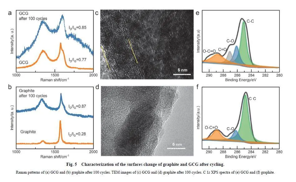
What’s more, the morphology and microstructure of GCGanode after 100 cycles is studied by the Raman spectrum, SEMand TEM to understand the influence of the graphene on theGCG. Fig. 5a,b show the Raman spectrums of GCG and graphiteafter 100 cycles. ID/IG of graphite increased from 0.28 to 0.87,which indicates the unstable structure of graphite during cycling.However, the ID/IG ratio of GCG almost did not change (from0.77 to 0.85), demonstrating a stable surface of GCG.
The images of GCG and graphite after 100 cycles can bedirectly observed from SEM and TME (Fig. S8–10, Fig. 5c,d).The obvious stratify of graphite in Fig. S10a means the damagedstructure after cycling which confirm the continuous exfoliationand the capacity decrease of graphite. However, the GCG has adense and uniform surface in the SEM (Fig. S10b), suggestingthat graphene can inhabit the exfoliation of graphite and keep thegraphite structure intact effectively. The TEM image shows astable SEI (about 5 nm) formed on the surface of GCG (Fig.5c). However, graphite has little SEI on the surface (Fig. 5d)because of the exfoliation of the layer structure during cycling.
Furthermore, the SEI contents on the surface of graphite andGCG were investigated by XPS analysis (Fig. 5e,f) after 100cycles. High-resolution C 1s spectra of GCG are deconvolutedinto four peaks at around 284.5, 286.2, 287.5, and 289 eV,corresponding to the presence of C―C, C―O, C=O, and O―C=O bonds. Compared to GCG, the C 1s spectra of graphitehave a high C ― C proportion which means little SEIcomposition on the surface after cycling. Although graphite can also form a SEI during cycling 32, the constant exfoliation leadsto a unstable SEI on the surface of graphite as the cycle going,which will cause a serve capacity decrease and a constantlydecomposition of electrolyte. On the contrary, although the sidereaction of electrolyte is inevitable in the beginning of cycling,the stable surface of GCG can restrain the exfoliation of graphite.Moreover, the F 1s of graphite and GCG also have muchdifferences (Fig. S11, Supporting Information). The graphite hasa very low element percentage content (0.24%) which is lessthan 1%, so the F 1s peak is not obvious. However, the GCG hasa higher content of F (1.94%). And the peaks of KF (Fig. S10)also mean that a robust inorganic-rich SEI has been formedduring cycling. The inconspicuous P peak might be due to thesmall amount of content (lt; 1%) on the surface of graphite andGCG. In a word, further analysis shows that the artificial SEI ofGCG can form a stable surface to restrain the exfoliation ofgraphite and achieving an ultralong cycling life.
4 Conclusions
In this study, we demonstrated that the interface of graphiteplays an important role in both cycling and rate performance.Through microwave reduction of GO, we can get a highly stableinterface which can not only reduce the side reaction of graphitewith electrolyte, but also can adapt the volume change duringcycling to keep the structure intact of graphite. The obtainedGCG had a superior electrochemical performance, with a stablecycling over 3000 cycles at a current density of 0.2 A·g?1.Different characterization techniques such as XPS and Ramanhad proved that graphene as the coating film can prevent severeexfoliation and constant formation of SEI in graphite, which willcause the fast capacity decrease. GITT and EIS confirmed thatgraphene accelerates the kinetics process. This artificial SEIstrategy provides a new approach to get a stable graphite anodefor next potassium ion battery with high energy densities.
Author Contributions: Conceptualization, Tao Xu and JieZhou; Methodology, Tao Xu; Software, Tao Xu; Validation,Tianci Kong and Wei Sun; Formal Analysis, Tao Xu;Investigation, Tao Xu; Resources, Tao Xu; Data Curation, TaoXu; Writing-Original Draft Preparation, Tao Xu; Writing-Review amp; Editing, Tao Xu; Visualization, Tao Xu; Supervision,Jie Zhou and Yitai Qian; Project Administration, Jie Zhou andYitai Qian; Funding Acquisition, Jie Zhou and Yitai Qian.
Supporting Information: available free of charge via the internet at http://www.whxb.pku.edu.cn.
References
(1) Goodenough, J. B. Nat. Electron. 2018, 1 (3), 204.doi: 10.1038/s41928-018-0048-6
(2) Tarascon, J.-M. Nat. Chem. 2010, 2 (6), 510. doi: 10.1038/nchem.680
(3) Larcher, D.; Tarascon, J. M. Nat. Chem. 2015, 7 (1), 19.doi: 10.1038/nchem.2085
(4) Eftekhari, A.; Jian, Z.; Ji, X. ACS Appl. Mater. Interfaces 2017, 9 (5),4404. doi: 10.1021/acsami.6b07989
(5) Wu, X.; Leonard, D. P.; Ji, X. Chem. Mater. 2017, 29 (12), 5031.doi: 10.1021/acs.chemmater.7b01764
(6) Pramudita, J. C.; Sehrawat, D.; Goonetilleke, D.; Sharma, N. Adv.Energy Mater. 2017, 7 (24), 1602911. doi: 10.1002/aenm.201602911
(7) Zhao, J.; Zou, X.; Zhu, Y.; Xu, Y.; Wang, C. Adv. Funct. Mater. 2016,26 (44), 8103. doi: 10.1002/adfm.201602248
(8) Komaba, S.; Hasegawa, T.; Dahbi, M.; Kubota, K. Electrochem.Commun. 2015, 60, 172. doi: 10.1016/j.elecom.2015.09.002
(9) Kim, H.; Hyun, J. C.; Jung, J. I.; Lee, J. B.; Choi, J.; Cho, S. Y.; Jin,H.-J.; Yun, Y. S. J. Mater. Chem. A 2022, 10 (4), 2055.doi: 10.1039/d1ta08981a
(10) Jian, Z.; Xing, Z.; Bommier, C.; Li, Z.; Ji, X. Adv. Energy Mater.2016, 6 (3), 1501874. doi: 10.1002/aenm.201501874
(11) Jian, Z.; Luo, W.; Ji, X. J. Am. Chem. Soc. 2015, 137 (36), 11566.doi: 10.1021/jacs.5b06809
(12) Zhang, R.; Huang, J.; Deng, W.; Bao, J.; Pan, Y.; Huang, S.; Sun,C.-F. Angew. Chem. Int. Ed. 2019, 58 (46), 16474.doi: 10.1002/anie.201909202
(13) Yoo, E.; Kim, J.; Hosono, E.; Zhou, H.-S.; Kudo, T.; Honma, I.Nano Lett. 2008, 8 (8), 2277. doi: 10.1021/nl800957b
(14) Liang, K.; Li, M.; Hao, Y.; Yan, W.; Cao, M.; Fan, S.; Han, W.; Su, J.Chem. Eng. J. 2020, 394, 124956. doi: 10.1016/j.cej.2020.124956
(15) Liu, C.; Fang, Z.; Li, X.; Zhou, J.; Yang, G.; Peng, L.; Guo, X.; Ding,W.; Hou, W. Nano Res. 2022, 16 (2), 2463.doi: 10.1007/s12274-022-4994-y
(16) Wang, J.; Yin, B.; Gao, T.; Wang, X.; Li, W.; Hong, X.; Wang, Z.; He,H. Acta Phys. -Chim. Sin. 2022, 38 (2), 2012088. [王鍵, 尹波, 高天,王星懿, 李望, 洪興星, 汪竹青, 何海勇. 物理化學學報, 2022, 38(2), 2012088.] doi: 10.3866/PKU.WHXB202012088
(17) Liu, W.; Li, H.; Jin, J.; Wang, Y.; Zhang, Z.; Chen, Z.; Wang, Q.;Chen, Y.; Paek, E.; Mitlin, D. Angew. Chem. Int. Ed. 2019, 58 (46),16590. doi: 10.1002/anie.201906612
(18) Voiry, D.; Yang, J.; Kupferberg, J.; Fullon, R.; Lee, C.; Jeong, H. Y.;Shin, H. S.; Chhowalla, M. Science 2016, 353 (6306), 1413.doi: 10.1126/science.aah3398
(19) Zhang, Y.; Chen, X.; Cen, W.; Ren, W.; Guo, H.; Vvu, S.; Xiao, Y.;Chen, S.; Guo, Y.; Xiao, D.; et al. Nano Res. 2022, 15 (5), 4083.doi: 10.1007/s12274-021-4023-6
(20) Baddour-Hadjean, R.; Pereira-Ramos, J.-P. Chem. Rev. 2010, 110 (3),1278. doi: 10.1021/cr800344k
(21) Zheng, J. M.; Engelhard, M. H.; Mei, D. H.; Jiao, S. H.; Polzin, B. J.;Zhang, J. G.; Xu, W. Nat. Energy 2017, 2 (3), 17012.doi: 10.1038/nenergy.2017.12
(22) Jiao, S.; Ren, X.; Cao, R.; Engelhard, M. H.; Liu, Y.; Hu, D.; Mei, D.;Zheng, J.; Zhao, W.; Li, Q.; et al. Nat. Energy. 2018, 3 (9), 739.doi: 10.1038/s41560-018-0199-8
(23) Lou, S.; Cheng, X.; Wang, L.; Gao, J.; Li, Q.; Ma, Y.; Gao, Y.; Zuo,P.; Du, C.; Yin, G. J. Power Sources 2017, 361, 80.doi: 10.1016/j.jpowsour.2017.06.023
(24) Kim, H.; Hong, J.; Park, Y.-U.; Kim, J.; Hwang, I.; Kang, K. Adv.Funct. Mater. 2015, 25 (4), 534. doi: 10.1002/adfm.201402984
(25) Augustyn, V.; Simon, P.; Dunn, B. Energy Environ. Sci. 2014, 7 (5),1597. doi: 10.1039/c3ee44164d
(26) Qin, L.; Xiao, N.; Zheng, J.; Lei, Y.; Zhai, D.; Wu, Y. Adv. EnergyMater. 2019, 9 (44), 1902618. doi: 10.1002/aenm.201902618
(27) Lin, X.; Dong, Y.; Chen, X.; Liu, H.; Liu, Z.; Xing, T.; Li, A.; Song,H. J. Mater. Chem. A 2021, 9 (10), 6423. doi: 10.1039/d1ta00178g
(28) Shaju, K. M.; Rao, G. V. S.; Chowdari, B. V. R. J. Electrochem Soc.2004, 151 (9), A1324. doi: 10.1149/1.1775218
(29) Funabiki, A.; Inaba, M.; Ogumi, Z.; Yuasa, S.; Otsuji, J.; Tasaka, A.J. Electrochem. Soc. 1998, 145 (1), 172. doi: 10.1149/1.1838231
(30) Meng, C.; Yuan, M.; Cao, B.; Lin, X.; Zhang, J.; Li, A.; Chen, X.;Jia, M.; Song, H. Carbon 2022, 192, 347.doi: 10.1016/j.carbon.2022.02.039
(31) Li, Q.; Zhang, Y.; Chen, Z.; Zhang, J.; Tao, Y.; Yang, Q.-H. Adv. EnergyMater. 2022, 12 (35), 2201574. doi: 10.1002/aenm.202201574
(32) Fan, L.; Ma, R.; Zhang, Q.; Jia, X.; Lu, B. Angew. Chem. Int. Ed.2019, 58 (31), 10500. doi: 10.1002/anie.201904258
國家自然科學基金(22201275, 21975244, 21831006), 中央高校基本業務費專項基金(WK2060000036), 安徽省自然科學基金(2208085QB32)資助項目
猜你喜歡
艦船科學技術(2022年16期)2022-09-22 02:15:00
北京航空航天大學學報(2021年6期)2021-07-20 07:23:54
當代陜西(2020年13期)2020-08-24 08:22:02
制造技術與機床(2017年5期)2018-01-19 02:49:17
制造技術與機床(2017年11期)2017-12-18 06:47:29
金秋(2017年4期)2017-06-07 08:22:16
蘇州科技大學學報(自然科學版)(2017年1期)2017-03-20 15:25:18
中國材料進展(2016年10期)2016-12-26 06:50:20
濰坊學院學報(2016年2期)2016-12-01 13:00:11
新聞傳播(2015年11期)2015-07-18 11:15:04